EP0407579B1 - Appareil de formation d'images par resonance magnetique - Google Patents
Appareil de formation d'images par resonance magnetique Download PDFInfo
- Publication number
- EP0407579B1 EP0407579B1 EP89902534A EP89902534A EP0407579B1 EP 0407579 B1 EP0407579 B1 EP 0407579B1 EP 89902534 A EP89902534 A EP 89902534A EP 89902534 A EP89902534 A EP 89902534A EP 0407579 B1 EP0407579 B1 EP 0407579B1
- Authority
- EP
- European Patent Office
- Prior art keywords
- signal
- signals
- radio frequency
- frequency coils
- magnetic resonance
- Prior art date
- Legal status (The legal status is an assumption and is not a legal conclusion. Google has not performed a legal analysis and makes no representation as to the accuracy of the status listed.)
- Expired - Lifetime
Links
Images


Classifications
-
- G—PHYSICS
- G01—MEASURING; TESTING
- G01R—MEASURING ELECTRIC VARIABLES; MEASURING MAGNETIC VARIABLES
- G01R33/00—Arrangements or instruments for measuring magnetic variables
- G01R33/20—Arrangements or instruments for measuring magnetic variables involving magnetic resonance
- G01R33/28—Details of apparatus provided for in groups G01R33/44 - G01R33/64
- G01R33/32—Excitation or detection systems, e.g. using radio frequency signals
- G01R33/36—Electrical details, e.g. matching or coupling of the coil to the receiver
- G01R33/3621—NMR receivers or demodulators, e.g. preamplifiers, means for frequency modulation of the MR signal using a digital down converter, means for analog to digital conversion [ADC] or for filtering or processing of the MR signal such as bandpass filtering, resampling, decimation or interpolation
-
- G—PHYSICS
- G01—MEASURING; TESTING
- G01R—MEASURING ELECTRIC VARIABLES; MEASURING MAGNETIC VARIABLES
- G01R33/00—Arrangements or instruments for measuring magnetic variables
- G01R33/20—Arrangements or instruments for measuring magnetic variables involving magnetic resonance
- G01R33/28—Details of apparatus provided for in groups G01R33/44 - G01R33/64
- G01R33/32—Excitation or detection systems, e.g. using radio frequency signals
- G01R33/34—Constructional details, e.g. resonators, specially adapted to MR
- G01R33/341—Constructional details, e.g. resonators, specially adapted to MR comprising surface coils
- G01R33/3415—Constructional details, e.g. resonators, specially adapted to MR comprising surface coils comprising arrays of sub-coils, i.e. phased-array coils with flexible receiver channels
Definitions
- the present invention relates to a magnetic resonance imaging apparatus that reconstructs an image using magnetic resonance signals received by a plurality of radio frequency coils.
- radio frequency magnetic resonance signals generated in an object body are received by radio frequency coils (RF coils).
- MR signals radio frequency magnetic resonance signals
- RF coils radio frequency coils
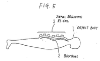
- This process may operate on the so-called multiple coil method whereby a plurality of RF coils receive MR signals, as illustratively shown in Fig. 5.
- This figure depicts a prior art case where a tomogram is taken of a backbone 2 in an object body 1.
- a plurality of RF coils 3 are positioned on the back of the object body 1 along the backbone 2 in order to receive the MR signals from within the body.
- US 4 721 913 discloses an apparatus as in the preamble of claim 1.
- Fig. 6 highlights an RF signal receiving system of a prior art MRI apparatus operating on the multiple coil method.
- Fig. 6 highlights an RF signal receiving system of a prior art MRI apparatus operating on the multiple coil method.
- reference numerals 11 through N designate a plurality of RF coils arranged parallel to the slice plane of the object body 1.
- RF signals received by the RF coils are amplified respectively by preamplifiers 11a through Na.
- the amplified signals enter receivers 11b through Nb that perform such signal processes as frequency conversion, amplification, detection and analog-to-digital (A/D) conversion.
- the processed signals then enter an image reconstructing device 19.
- the image reconstructing device 19 reconstructs a plurality of images based on the multiple input signals, and combines these images into a single image.
- Reference numeral 20 is the object body's sensitive area corresponding to each of the RF coils 11 through N. Adjoining sensitive areas have a mutually overlapping portion therebetween.
- the images stemming from these sensitive areas are reconstructed by the image reconstructing device 19 into a single image.
- This multiple coil method is characterized by the fact that the overall sensitive region corresponding to the received MR signals is extensive in the field of view (crosswise) but shallow in the object body's depth direction. That is, the method is suitable for the imaging of backbones or like areas with good S/N ratios.
- One disadvantage of the multiple coil method is the need for an expanded hardware construction involving pluralities of preamplifiers and receivers associated with the multiple RF coils.
- Another disadvantage is that the image reconstructing device 19 is required to perform greater amounts of computations for image reconstruction because the device must reconstruct each one of the images associated with the sensitive areas of the coils based on the RF signals coming therefrom.
- MRI magnetic resonance imaging
- an MRI apparatus comprising a plurality of radio frequency (RF) coils, a plurality of signal composers, a plurality of receivers, and an image reconstructing device.
- the RF coils are positioned on the surface of an object body to receive MR signals coming therefrom, the sensitive areas of the adjoining RF coils having a mutually overlapping portion therebetween.
- the signal composers are provided to address each group of RF coils whose sensitive areas do not overlap.
- One signal composer composes a single received signal out of the signals from the RF coils in one group.
- the receivers carry out such signal processes as detection and A/D conversion on the signals coming from the signal composers.
- the image reconstructing device reconstructs images based on the output signals from the receivers and puts these images together into a single reconstructed image.
- Fig. 1 is a conceptual view of how the first embodiment of the invention is constructed.
- reference numerals 11 through N are a plurality of RF coils positioned along the slice plane of an object body 1.
- the RF coils 11 through N are associated with their respective sensitive areas.
- the sensitive areas of adjoining RF coils share an overlapping portion between.
- Numeral 31 is a first signal composer which receives signals from odd-numbered RF coils 11 through N-1 and which composes a signal out of these input signals.
- Numeral 32 is a second signal composer which receives signals from even-numbered RF coils 12 through N and which also composes a signal out of these input signals.
- Numerals 31a and 32a are preamplifiers that respectively amplify the outputs from the signal composers 31 and 32.
- Numerals 31b and 32b are receivers that perform such signal processes as frequency conversion, amplification, detection and A/D conversion on the output signals from the preamplifiers 31a and 32a, respectively.
- Numeral 19 is an image reconstructing device that reconstructs an image using the output signals from the receivers 31b and 32b.
- the first embodiment works as follows. Of the RF coils that have received MR signals, the odd-numbered RF coils 11 through N-1 forward their MR signals to the first signal composer 31.
- the signal composer 31 composes the received signals into a signal received signal.
- the even-numbered RF coils 12 through N forward their MR signals to the second signal composer 32 which composes these signals into another received signal.
- the received signals from the signal composers 31 and 32 are amplified by the preamplifiers 31a and 32a, respectively.
- the amplified signals are subjected to such signal processes as frequency conversion, amplification, detection and D/A conversion by the receivers 31b and 32b.
- the processed signals then enter the image reconstructing device 19.
- every second coil i.e., any of odd-numbered or even-numbered RF coils
- every second coil i.e., any of odd-numbered or even-numbered RF coils
- the signals do not cancel one another because of their overlapping portions.
- the received signal from the first signal composer 31 causes shaded images of Fig. 2A to be reconstructed, while the signal from the second signal composer 32 results in reconstructed images shown shaded in Fig. 2B.
- reference numerals 41 through 44 are the reconstructed images respectively corresponding to the sensitive areas of the RF coils 11 through 14.
- the image reconstructing device 19 composes the reconstructed images from these two sections into one image 50 shown in Fig. 2C.
- the image 50 is the sum of all images associated with the sensitive areas of all RF coils.
- This embodiment only requires two receiving sections (each comprising preamplifiers, receivers, etc.) and two passes of image reconstruction computations regardless of the number of the RF coils configured. In an example where eight RF coils are used, the bulk of the receiving section hardware and the amount of image reconstruction computations are both reduced to one fourth of the levels of the comparable prior art.
- the signal-to-noise ratio may deteriorate.
- the signals from the RF coils 11 through N are amplified by preamplifiers 11a through Na before they are input to the signal composers 31 and 32, as shown in Fig. 3.
- the number of preamplifiers remains the same, the bulk of the hardware downstream of the receivers may be reduced, and so is the amount of the image reconstruction computations involved.
- the present invention may also be practiced with an alternative arrangement of RF coils.
- the multiple RF coils may be arranged in a two-dimensional pattern, as depicted in Fig. 4.
- the area of the 2D coil pattern is the same as that of the single-row coil arrangement.
- those not adjoining one another are connected to a different signal composer for signal composition. That is, three RF coils marked "A" are connected to a signal composer, three RF coils marked "B” to another signal composer, two RF coils marked “C” to yet another signal composer, and one RF coil is connected to one signal receiver.
- nine RF coils require only four sections of the signal receiving hardware and four passes of image reconstruction computations.
Abstract
Claims (5)
- Appareil de formation d'images par résonance magnétique comprenant :- une pluralité de bobines de radiofréquence (11, 12,... N-1, N) qui sont positionnées le long de la surface d'un corps (1) et qui correspondent à des zones sensibles dudit corps (1) pour recevoir des signaux de résonance magnétique (MR) et pour produire des signaux de sortie respectifs,- un dispositif de composition de signal (31, 32) pour recevoir les signaux de sortie des bobines de radiofréquence (11, 12,..., N-1, N),- un dispositif de réception (31b, 32b) raccordé à une sortie dudit dispositif de composition de signal (31, 32) pour réaliser des traitements de signaux tels qu'une détection et une conversion A/N ; et- un dispositif de reconstruction d'image (19) qui reconstruit une image unique à partir du signal de sortie desdits dispositifs de réception (31b, 32b),- ladite pluralité de bobines de radiofréquence (11, 12,..., N-1, N) sont disposées pour être positionnées le long de la surface du corps (1) pour que lesdites zones sensibles dudit corps (1) partagent des parties de recouvrement entre elles où leurs bobines de radiofréquence correspondantes (11, 12,..., N-1, N) sont respectivement voisines les unes des autres, caractérisé en ce que- ledit dispositif de composition de signal (31, 32) comprend une pluralité d'unités de composition de signal associées chacune à un groupe différent desdites bobines de radiofréquence (11, 12,..., N-1, N) dont des zones sensibles correspondantes ne se recouvrent pas l'une l'autre, chacune desdites unités de composition de signal prenant des signaux reçus desdites bobines de radiofréquence dans un groupe et composant lesdits signaux reçus en un signal reçu unique ;- ledit dispositif de réception (31b, 32b) comprend une pluralité de récepteurs pour réaliser le traitement de signaux sur les signaux de sortie à partir desdites unités de composition de signal ; et- ledit dispositif de reconstruction d'image (19) reconstruit des images à partir des signaux de sortie de ladite pluralité de récepteurs et compose lesdites images reconstruites en ladite image unique.
- Appareil de formation d'images par résonance magnétique selon la revendication 1, caractérisé en outre en ce qu'il comprend une pluralité de préamplificateurs (31a, 32a) entre ladite pluralité d'unités de composition de signal (31, 32) et ladite pluralité de récepteurs (31b, 32b), lesdits préamplificateurs (31a, 32a) amplifiant les signaux de sortie desdites unités de composition de signal (31, 32) avant que lesdits signaux atteignent lesdits récepteurs (31b, 32b) (figure 1).
- Appareil de formation d'images par resonance magnétique selon la revendication 1, caractérisé en outre en ce qu'il comprend une pluralité de préamplificateurs (11a, 12a,.., (N-1)a, Na) entre ladite pluralité de bobines de radiofréquence (11, 12,..., N-1, N) et ladite pluralité d'unités de composition de signal (31, 32), lesdits préamplificateurs amplifiant les signaux de sortie reçus desdites bobines de radiofréquence (figure 3).
- Appareil de formation d'images par résonance magnétique selon la revendication 1, caractérisé en ce que ladite pluralité de bobines de radiofréquence (11, 12,..., N-1, N) est disposée en une rangée unique.
- Appareil de formation d'images par résonance magnétique selon la revendication 1, caractérisé en ce que ladite pluralité de bobines de radiofréquence (11, 12,.., N-1, N) est disposée dans une forme bidimensionnelle.
Applications Claiming Priority (3)
| Application Number | Priority Date | Filing Date | Title |
|---|---|---|---|
| JP32083/88 | 1988-02-15 | ||
| JP63032083A JPH01207044A (ja) | 1988-02-15 | 1988-02-15 | 核磁気共鳴画像診断装置の受信装置 |
| PCT/JP1989/000154 WO1989007416A1 (fr) | 1988-02-15 | 1989-02-15 | Appareil de formation d'images par resonance magnetique |
Publications (3)
| Publication Number | Publication Date |
|---|---|
| EP0407579A1 EP0407579A1 (fr) | 1991-01-16 |
| EP0407579A4 EP0407579A4 (en) | 1991-09-11 |
| EP0407579B1 true EP0407579B1 (fr) | 1996-08-28 |
Family
ID=12348982
Family Applications (1)
| Application Number | Title | Priority Date | Filing Date |
|---|---|---|---|
| EP89902534A Expired - Lifetime EP0407579B1 (fr) | 1988-02-15 | 1989-02-15 | Appareil de formation d'images par resonance magnetique |
Country Status (5)
| Country | Link |
|---|---|
| US (1) | US5122749A (fr) |
| EP (1) | EP0407579B1 (fr) |
| JP (1) | JPH01207044A (fr) |
| DE (1) | DE68927049T2 (fr) |
| WO (1) | WO1989007416A1 (fr) |
Families Citing this family (10)
| Publication number | Priority date | Publication date | Assignee | Title |
|---|---|---|---|---|
| GB8814187D0 (en) * | 1988-06-15 | 1988-07-20 | Mansfield P | Improvements in/relating to surface electrical coil structures |
| JP3110741B2 (ja) * | 1990-07-18 | 2000-11-20 | 株式会社東芝 | 磁気共鳴イメージング装置 |
| US5086275A (en) * | 1990-08-20 | 1992-02-04 | General Electric Company | Time domain filtering for nmr phased array imaging |
| US5138260A (en) * | 1990-11-21 | 1992-08-11 | Picker International, Inc. | Computer controlled switching of multiple rf coils |
| US5374890A (en) * | 1992-07-24 | 1994-12-20 | Picker International, Inc. | Simultaneous magnetic resonance imaging of multiple human organs |
| DE4412446C2 (de) * | 1994-04-12 | 1996-09-12 | Bruker Medizintech | Verfahren und Vorrichtung zur Erstellung eines NMR-Tomographiebildes |
| DE10003712C2 (de) | 2000-01-28 | 2002-12-12 | Siemens Ag | Verfahren zur Selektion einer Lokalantenne |
| WO2004001435A1 (fr) | 2002-06-21 | 2003-12-31 | Koninklijke Philips Electronics N.V. | Appareil et procede d'imagerie par resonance magnetique |
| US7109710B2 (en) * | 2003-10-17 | 2006-09-19 | General Electric Company | Method and apparatus to improve signal-to-noise ratio without compromising field-of-view for simultaneous MR data acquisition by an array of RF coils of an MR scanner |
| JP4961116B2 (ja) * | 2005-06-15 | 2012-06-27 | 株式会社日立メディコ | 磁気共鳴撮影装置 |
Citations (2)
| Publication number | Priority date | Publication date | Assignee | Title |
|---|---|---|---|---|
| JPS60376A (ja) * | 1983-06-15 | 1985-01-05 | Yokogawa Medical Syst Ltd | 核磁気共鳴イメ−ジング装置におけるrfコイル装置 |
| US4721913A (en) * | 1985-05-08 | 1988-01-26 | Mcw Research Foundation, Inc. | NMR local coil network |
Family Cites Families (9)
| Publication number | Priority date | Publication date | Assignee | Title |
|---|---|---|---|---|
| GB1580787A (en) * | 1976-04-14 | 1980-12-03 | Mansfield P | Nuclear magnetic resonance apparatus and methods |
| JPS60190846A (ja) * | 1984-03-10 | 1985-09-28 | Jeol Ltd | 核磁気共鳴装置 |
| US4620155A (en) * | 1984-08-16 | 1986-10-28 | General Electric Company | Nuclear magnetic resonance imaging antenna subsystem having a plurality of non-orthogonal surface coils |
| NL8603006A (nl) * | 1986-11-27 | 1988-06-16 | Philips Nv | Magnetisch resonantie apparaat met gestapeld oppervlakte spoelenstelsel. |
| NL8603005A (nl) * | 1986-11-27 | 1988-06-16 | Philips Nv | Magnetisch resonantie apparaat met flexibele quadratuur spoelenstelsel. |
| US4943775A (en) * | 1986-11-27 | 1990-07-24 | U.S. Philips Corporation | Magnetic resonance apparatus with uncoupled rf coils |
| JPH05166Y2 (fr) * | 1987-02-28 | 1993-01-06 | ||
| US4825162A (en) * | 1987-12-07 | 1989-04-25 | General Electric Company | Nuclear magnetic resonance (NMR) imaging with multiple surface coils |
| NL8802959A (nl) * | 1988-12-01 | 1990-07-02 | Philips Nv | Rf spoelensysteem met meerdere oppervlaktespoelen. |
-
1988
- 1988-02-15 JP JP63032083A patent/JPH01207044A/ja active Pending
-
1989
- 1989-02-15 EP EP89902534A patent/EP0407579B1/fr not_active Expired - Lifetime
- 1989-02-15 WO PCT/JP1989/000154 patent/WO1989007416A1/fr active IP Right Grant
- 1989-02-15 US US07/555,490 patent/US5122749A/en not_active Expired - Fee Related
- 1989-02-15 DE DE68927049T patent/DE68927049T2/de not_active Expired - Fee Related
Patent Citations (2)
| Publication number | Priority date | Publication date | Assignee | Title |
|---|---|---|---|---|
| JPS60376A (ja) * | 1983-06-15 | 1985-01-05 | Yokogawa Medical Syst Ltd | 核磁気共鳴イメ−ジング装置におけるrfコイル装置 |
| US4721913A (en) * | 1985-05-08 | 1988-01-26 | Mcw Research Foundation, Inc. | NMR local coil network |
Also Published As
| Publication number | Publication date |
|---|---|
| EP0407579A1 (fr) | 1991-01-16 |
| JPH01207044A (ja) | 1989-08-21 |
| DE68927049D1 (de) | 1996-10-02 |
| US5122749A (en) | 1992-06-16 |
| EP0407579A4 (en) | 1991-09-11 |
| DE68927049T2 (de) | 1997-02-06 |
| WO1989007416A1 (fr) | 1989-08-24 |
Similar Documents
| Publication | Publication Date | Title |
|---|---|---|
| US5389880A (en) | Magnetic resonance imaging apparatus | |
| JP3391860B2 (ja) | 円偏波局所アンテナ装置 | |
| EP0407579B1 (fr) | Appareil de formation d'images par resonance magnetique | |
| US6377044B1 (en) | Multi-mode receiver coils for MRI | |
| US7109713B2 (en) | RF coil and magnetic resonance imaging apparatus | |
| US5473251A (en) | Magnetic resonance imaging apparatus | |
| US5394087A (en) | Multiple quadrature surface coil system for simultaneous imaging in magnetic resonance systems | |
| US20060033497A1 (en) | Degenerate birdcage coil and transmit/receive apparatus and method for same | |
| JP5260819B2 (ja) | 並列式mriを用いた撮像を高速化させるための方法及びシステム | |
| EP0616229B1 (fr) | Appareil et procédés pour l'imagerie par résonance magnétique | |
| EP1360516B1 (fr) | Appareil d'imagerie par resonance magnetique | |
| US5280246A (en) | Nuclear magnetic resonance apparatus | |
| JP3727469B2 (ja) | 受信信号処理回路およびmri装置 | |
| US6914432B2 (en) | Phased array coil assembly and method and system for employing the same | |
| EP0695951A1 (fr) | Procédé et appareil par résonance magnétique | |
| US4145614A (en) | Device for producing two- and/or three-dimensional images of three dimensional objects | |
| US8054078B2 (en) | Parallel imaging method and MRI apparatus | |
| US7157910B2 (en) | Magnetic resonance imaging apparatus and method | |
| JP2680235B2 (ja) | 核磁気共鳴装置用プローブ | |
| JP4266580B2 (ja) | 磁気共鳴イメージング用rfコイル | |
| US5572130A (en) | Method and apparatus for the production of an NMR tomography image using an array of surface coils and multiplexers | |
| EP0815462B1 (fr) | Circuit de combinaison pour systeme de bobines de mesure rf permettant de detecter des signaux de resonnance magnetique | |
| JP3415754B2 (ja) | Mri装置 | |
| US4398148A (en) | Electromagnetic coil system for examination of large objects by nuclear magnetic resonance and whole-body imaging machine using a system | |
| US8698500B2 (en) | Magnetic resonance tomography system |
Legal Events
| Date | Code | Title | Description |
|---|---|---|---|
| PUAI | Public reference made under article 153(3) epc to a published international application that has entered the european phase |
Free format text: ORIGINAL CODE: 0009012 |
|
| 17P | Request for examination filed |
Effective date: 19900814 |
|
| AK | Designated contracting states |
Kind code of ref document: A1 Designated state(s): DE FR GB |
|
| A4 | Supplementary search report drawn up and despatched |
Effective date: 19910722 |
|
| AK | Designated contracting states |
Kind code of ref document: A4 Designated state(s): DE FR GB |
|
| 17Q | First examination report despatched |
Effective date: 19940622 |
|
| GRAH | Despatch of communication of intention to grant a patent |
Free format text: ORIGINAL CODE: EPIDOS IGRA |
|
| GRAH | Despatch of communication of intention to grant a patent |
Free format text: ORIGINAL CODE: EPIDOS IGRA |
|
| GRAA | (expected) grant |
Free format text: ORIGINAL CODE: 0009210 |
|
| AK | Designated contracting states |
Kind code of ref document: B1 Designated state(s): DE FR GB |
|
| REF | Corresponds to: |
Ref document number: 68927049 Country of ref document: DE Date of ref document: 19961002 |
|
| ET | Fr: translation filed | ||
| PGFP | Annual fee paid to national office [announced via postgrant information from national office to epo] |
Ref country code: FR Payment date: 19970115 Year of fee payment: 9 |
|
| PGFP | Annual fee paid to national office [announced via postgrant information from national office to epo] |
Ref country code: DE Payment date: 19970117 Year of fee payment: 9 |
|
| PGFP | Annual fee paid to national office [announced via postgrant information from national office to epo] |
Ref country code: GB Payment date: 19970127 Year of fee payment: 9 |
|
| PLBE | No opposition filed within time limit |
Free format text: ORIGINAL CODE: 0009261 |
|
| STAA | Information on the status of an ep patent application or granted ep patent |
Free format text: STATUS: NO OPPOSITION FILED WITHIN TIME LIMIT |
|
| 26N | No opposition filed | ||
| PG25 | Lapsed in a contracting state [announced via postgrant information from national office to epo] |
Ref country code: GB Free format text: LAPSE BECAUSE OF NON-PAYMENT OF DUE FEES Effective date: 19980215 |
|
| PG25 | Lapsed in a contracting state [announced via postgrant information from national office to epo] |
Ref country code: FR Free format text: THE PATENT HAS BEEN ANNULLED BY A DECISION OF A NATIONAL AUTHORITY Effective date: 19980228 |
|
| GBPC | Gb: european patent ceased through non-payment of renewal fee |
Effective date: 19980215 |
|
| PG25 | Lapsed in a contracting state [announced via postgrant information from national office to epo] |
Ref country code: DE Free format text: LAPSE BECAUSE OF NON-PAYMENT OF DUE FEES Effective date: 19981103 |
|
| REG | Reference to a national code |
Ref country code: FR Ref legal event code: ST |