EP0407070A2 - Maschinen für die Herstellung von Plastikstoffrollen - Google Patents
Maschinen für die Herstellung von Plastikstoffrollen Download PDFInfo
- Publication number
- EP0407070A2 EP0407070A2 EP90306849A EP90306849A EP0407070A2 EP 0407070 A2 EP0407070 A2 EP 0407070A2 EP 90306849 A EP90306849 A EP 90306849A EP 90306849 A EP90306849 A EP 90306849A EP 0407070 A2 EP0407070 A2 EP 0407070A2
- Authority
- EP
- European Patent Office
- Prior art keywords
- machine
- mandrel
- shaft
- rotatable
- roll
- Prior art date
- Legal status (The legal status is an assumption and is not a legal conclusion. Google has not performed a legal analysis and makes no representation as to the accuracy of the status listed.)
- Withdrawn
Links
Images

Classifications
-
- B—PERFORMING OPERATIONS; TRANSPORTING
- B65—CONVEYING; PACKING; STORING; HANDLING THIN OR FILAMENTARY MATERIAL
- B65H—HANDLING THIN OR FILAMENTARY MATERIAL, e.g. SHEETS, WEBS, CABLES
- B65H18/00—Winding webs
- B65H18/02—Supporting web roll
- B65H18/021—Multiple web roll supports
-
- B—PERFORMING OPERATIONS; TRANSPORTING
- B65—CONVEYING; PACKING; STORING; HANDLING THIN OR FILAMENTARY MATERIAL
- B65H—HANDLING THIN OR FILAMENTARY MATERIAL, e.g. SHEETS, WEBS, CABLES
- B65H75/00—Storing webs, tapes, or filamentary material, e.g. on reels
- B65H75/02—Cores, formers, supports, or holders for coiled, wound, or folded material, e.g. reels, spindles, bobbins, cop tubes, cans, mandrels or chucks
- B65H75/18—Constructional details
- B65H75/24—Constructional details adjustable in configuration, e.g. expansible
- B65H75/242—Expansible spindles, mandrels or chucks, e.g. for securing or releasing cores, holders or packages
- B65H75/248—Expansible spindles, mandrels or chucks, e.g. for securing or releasing cores, holders or packages expansion caused by actuator movable in axial direction
- B65H75/2484—Expansible spindles, mandrels or chucks, e.g. for securing or releasing cores, holders or packages expansion caused by actuator movable in axial direction movable actuator including wedge-like or lobed member
-
- B—PERFORMING OPERATIONS; TRANSPORTING
- B65—CONVEYING; PACKING; STORING; HANDLING THIN OR FILAMENTARY MATERIAL
- B65H—HANDLING THIN OR FILAMENTARY MATERIAL, e.g. SHEETS, WEBS, CABLES
- B65H2301/00—Handling processes for sheets or webs
- B65H2301/40—Type of handling process
- B65H2301/41—Winding, unwinding
- B65H2301/413—Supporting web roll
- B65H2301/4136—Mounting arrangements not otherwise provided for
- B65H2301/41362—Mounting arrangements not otherwise provided for one of the supports for the roller axis being movable as auxiliary bearing
Definitions
- This invention concerns improvements in and relating to machines for forming rolls of plastics material.
- Plastics material in sheet form is often required to be formed into rolls for transportation and storage. At present rolls of plastics sheet are formed on a hollow core or tube that is rotated to form the roll. At capacity, the machine has to be stopped for the plastics sheet material to be cut and the formed roll moved to be replaced by another hollow core or tube support. Thus, valuable production time is lost and expense incurred.
- An object of this invention is to provide an improved plastics sheet roll forming machine.
- a plastics sheet roll forming machine comprising a first rotatable part having locations for at least two rotatable plastics sheet roll supports, such as mandrels or core supports.
- the rotatable mandrels are preferably expandable and contractable between a first position for forming a plastics sheet material roll thereon and a second position for removing a completed roll from the mandrel.
- Expansion and contraction of the mandrel may be achieved in any suitable way but in one preferred embodiment the mandrel may be formed by loosely connected elongated leaves around a central shaft, the leaves and the shaft having cooperating parts, whereby movement of the shaft within the mandrel, which movement may be longitudinally or rotary, in one direction urges the mandrel leaves apart and in the other direction allows the mandrel to collapse.
- said cooperating parts are tapered members and said shaft movement is longitudinally of the mandrel.
- the first rotatable part is preferably a beam mounted on a rotatable shaft preferable supported at opposite ends in bearings and is preferable rotatable through 360 degrees.
- the machine of the invention will preferably have rotatable formations on the first rotatable part, such as cones, to fit into a core end and a retractable part at the opposite end of the machine also having formations, such as cones, to fit into a core end.
- the machine of the invention is preferably operated hydraulically and it is particularly desirable that a single power source feed all of the functions of the machine.
- the preferred power source is an hydraulic power source ideally situated at one end of the machine and having hydraulic feeds for the variations functions of the machine via suitable valves.
- the hydraulic power source preferably comprises a variable speed pressure compensated pump driven by an electric motor. Such a pump is preferred in order to give variable speeds and variable torque at various hydraulic motors in order to compensate for different plastics materials, sheet thickness and most particularly roll diameter which, is of course, increases as the roll if formed.
- the hydraulic pump will preferably feed hydraulic fluid via a valve to a hydraulic motor situated for rotation of said first rotatable part and with a valved feed to said second rotatable part, if present.
- Rotation of said first rotatable part is for changeover from one mandrel or core to the second mandrel or core when a roll is completed.
- Hydraulic fluid feed will also go to hydraulic motors for rotation of the mandrels or cores selectively, ie. to one or other of the mandrels or cores.
- the mandrels or cores are rotated to draw plastics sheet material from sheet material forming apparatus in a continuous fashion. It is important that as a roll of plastics material is completed, the second mandrel or core can be brought into operation as quickly as possible so as not to disrupt continuous formation of the sheet material by the sheet forming apparatus.
- additional hydraulic fluid feed may be required for a hydraulic cylinder for withdrawal of the core end supporting formation from one end thereof to release the core for removal from the machine and, of course, for pushing said core end supporting formation into the core end for roll formation on the core.
- the hydraulic cylinder is preferably at the end of the machine remote from the first rotatable part.
- Further hydraulic fluid feed may be required for expansion and contraction of the mandrels via suitable hydraulic motors or cylinders depending on the shaft movement required.
- All of the various hydraulic functions of the preferred machines of the invention will be valved for selection of an appropriate functions.
- Preferably controls for such valves will be at one location to enable easy and quick operation of the machine.
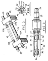
- a machine 10 for forming rolls of plastics sheet material comprises a supporting framework 12 for a shaft 14 rotatably mounted in bearings at each end. At one end the shaft 14 has a hydraulic motor 16 for rotating the shaft 14 and hence beam 18 mounted on the shaft.
- the beam 18 has either mandrels 20 rotatably mounted therefrom or support core cones 22 (see Figure 2). The mandrels 20 are rotated by means of hydraulic motors 26.
- the mandrels 20 are able to expand and contract being formed of leaves 30 loosely held together, which leaves have on their inner surface tapered formations 32 that cooperate with oppositely tapered formations 34 on shaft 36 through the centre of each mandrel.
- the shafts 36 are each coupled to a hydraulic cylinder 38 whereby longitudinal movement of the shaft 36 in one direction urges the leaves 30 apart and in the other direction allows the leaves to collapse toward each other.
- cone formations 22 are provided at opposite ends of the machine, which are to fit into opposite end of a roll core 40.
- the cone formation 22A is coupled to the hydraulic motor 26 for rotating the cone 22A and hence the core 40, whereas the cone formation 22B is coupled to an hydraulic cylinder 46 for movement into and out of engagement with roll core 40.
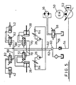
- FIG. 5 of the accompanying drawings shows an hydraulic system for operating a machine as shown in any of or all of the drawings.
- the hydraulic system comprises an electric motor 50 for driving a pressure compensated variable volume pump 52 to give variable speeds and variable torque at the hydraulic motors depending on the product being rolled and roll diameter.
- the hydraulic pump 52 supplies hydraulic fluid via main feed line 54 and branch line 56 to rotary motor 16 for rotating the shaft 18.
- the branch line 56 includes valve means 58 for controlling supply of hydraulic fluid to the motor 16.
- the main feed line 54 enters a rotary valve 60 which direct hydraulic fluid supply to one or other sides of the machine.
- the hydraulic system for each side of the machine is identical and includes off a feed line 62, valve means 64 and rotary motor 26 for rotating the mandrels 20 or roll support core cones 22A, off a feed line 70 via a valve 72 hydraulic cylinder 38 for expansion and contraction of the mandrels 20 and finally off a feed line 80 via valve means 82, hydraulic cylinder 42 for withdrawal from or insertion into a core 40 core support cone 22B.
- the illustrated machine operates by picking up the end of a sheet of plastics material from a sheet forming machine onto a rotating mandrel or core and forming a roll thereof on the mandrel or core.
- the machine then rotates on its central axis to bring the vacant mandrel or core into a working position.
- the sheet material is cut and the sheet material wound onto the vacant mandrel or core to give continuous production.
- the first roll is unloaded, which from a mandrel requires contraction thereof so that the roll can be slid off the mandrel and for a core requires withdrawal of cone 22B.
- the machine remains under constant torque required to wind the product.
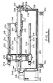
- a machine 200 for forming rolls of plastics sheet material as it comes off a production sheet comprises a frame 202 on wheels 204.
- the frame 202 has upstanding ends 206 that support in bearings 208 a rotatable shaft 210. Near one end the shaft 210 carries a fixed crosspiece 212 from which extend parallel to the shaft a pair of rotatable mandrels 214 diametrically opposed relative to the shaft. Adjacent the free ends of the mandrels on the shaft 210 are retractable support arms 216.
- Each mandrel 214 comprises an expansion shaft 218 and outer leaves 220 that are movable towards and away from the core by means of expansion pins 222 that are tapered and which contact oppositely tapered members on the leaves, whereby longitudinal movement thereof relative to the core will cause the leaves to move towards and away from the core as desired.
- the machine 200 is operated hydraulically and the frame carries at one end an hydraulic fluid tank 224 and an electric motor 226. Hydraulic fluid under pressure is supplied to the main shaft and each of the mandrels via hydraulic piping as shown (see also Figure 7 below).
- the main shaft requires hydraulic power for motor 228 for rotation thereof via sprockets 229 to swop mandrels when a completed roll has been formed on the one mandrel. The swap over has to be quick so that the plastics sheet production machine can be operated continuously.
- the main shaft also requires hydraulic power for the retractable support arms 216 which are operated by means of double acting rams 230.
- the end of each mandrel has a bearing 232 which fits into the end of the support arm to support the mandrel and to allow it to rotate as a roll of plastics material is formed thereon.
- Hydraulic fluid is also used to operate a disc brake 234 at one end of the main shaft.
- the mandrels require hydraulic power for their respective motors 250 for rotating same and for their respective double acting cylinders 252 for causing longitudinal movement of the expansion shaft 218 to expand or collapse the mandrel.
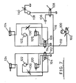
- the pump 102 supplies hydraulic fluid under pressure to valves 104, 106 and 108 for operating each rolling mandrel and the main shaft respectively.
- a single feed line 110 branches to form separate feed lines 112,114 and 116 to those valves.
- the valves 104 and 106 for the mandrels each control supply of hydraulic fluid to a double acting support arm piston 120, a mandrel rotate motor 122 and a double acting mandrel expand/contract piston 124.
- the valves and the feed/return lines therefrom are arranged so that in one valve state the mandrel, expands the mandrel rotates and the support arm engages the free end of the mandrel, and in its other state, the mandrel stops rotating, the mandrel contracts and the support arm is disengaged.
- the return line from the mandrel motor includes a variable flow restrictor valve 130.
- the third branch 116 from the pump 102 leads to the valve 108 which directs hydraulic fluid either to a disc brake 136 for the main shaft or a motor 138 for rotating the main shaft.
- a variable flow restrictor valve 140 is provided beyond the motor 138 in order to control its speed.
Landscapes
- Moulds For Moulding Plastics Or The Like (AREA)
- Casting Or Compression Moulding Of Plastics Or The Like (AREA)
Applications Claiming Priority (2)
| Application Number | Priority Date | Filing Date | Title |
|---|---|---|---|
| GB898914482A GB8914482D0 (en) | 1989-06-23 | 1989-06-23 | Improvements in and relating to machines for forming rolls of plastics materials |
| GB8914482 | 1989-06-23 |
Publications (2)
| Publication Number | Publication Date |
|---|---|
| EP0407070A2 true EP0407070A2 (de) | 1991-01-09 |
| EP0407070A3 EP0407070A3 (en) | 1991-06-26 |
Family
ID=10658967
Family Applications (1)
| Application Number | Title | Priority Date | Filing Date |
|---|---|---|---|
| EP19900306849 Withdrawn EP0407070A3 (en) | 1989-06-23 | 1990-06-22 | Improvements in and relating to machines for forming rolls of plastics material |
Country Status (2)
| Country | Link |
|---|---|
| EP (1) | EP0407070A3 (de) |
| GB (2) | GB8914482D0 (de) |
Cited By (9)
| Publication number | Priority date | Publication date | Assignee | Title |
|---|---|---|---|---|
| WO1996016888A1 (en) * | 1994-11-29 | 1996-06-06 | Gianfranco Galimberti | Equipment for the production of rolls of web material |
| FR2727952A1 (fr) * | 1994-12-09 | 1996-06-14 | Clecim Sa | Bobineuse d'enroulement d'une bande |
| DE19543046A1 (de) * | 1995-11-10 | 1997-05-15 | Mannesmann Ag | Karussellhaspel mit zwei Haspeldornen |
| EP0783956A1 (de) * | 1996-01-10 | 1997-07-16 | BURGOPACK STAMPA, TRASFORMAZIONE, IMBALLAGGI S.p.A. | Vorrichtung zum kontinuierlichen Heissiegeln von Kunststoff und/oder Papier ähnliche Bändern in ein oder mehrere gegenseitigen Kombinationen |
| EP0857679A2 (de) | 1997-02-06 | 1998-08-12 | WindmÀ¶ller & Hölscher | Vorrichtung zum Aufwickeln von bahnförmigem Material |
| EP0875476A1 (de) * | 1997-04-30 | 1998-11-04 | Kvaerner Metals Clecim | Wickler mit zwei Spindeln zum Aufwickeln einer Bahn |
| EP1391406A1 (de) * | 2002-08-17 | 2004-02-25 | Werner Mülfarth | Vorrichtung zum Aufwickeln von bahn- oder bandförmigen Materialien |
| EP2039634A1 (de) * | 2007-09-20 | 2009-03-25 | Valmet Atlas Plc | Bahnwickelmaschinen und Verfahren zum Betrieb von Bahnwickelmaschinen |
| CN103640920A (zh) * | 2013-11-19 | 2014-03-19 | 佘峰 | 一种模切机的胶带驱动装置 |
Families Citing this family (1)
| Publication number | Priority date | Publication date | Assignee | Title |
|---|---|---|---|---|
| DE4414003C2 (de) * | 1994-04-22 | 2000-04-13 | Kampf Gmbh & Co Maschf | Vorrichtung zum Aufwickeln von Warenbahnen, insbesondere Kunststoffolien in einer zwei Drehscheiben aufweisenden Mehrfach-Wendewickelmaschine |
Family Cites Families (10)
| Publication number | Priority date | Publication date | Assignee | Title |
|---|---|---|---|---|
| US2095123A (en) * | 1935-08-17 | 1937-10-05 | Self Locking Carton Co | Wax paper machine |
| US2650038A (en) * | 1947-03-29 | 1953-08-25 | Crystal Waxing Company | Automatic web rewinding machine |
| GB718569A (en) * | 1952-05-03 | 1954-11-17 | Goss Printing Press Co Ltd | Improvements in or relating to web supply reel for printing presses |
| US2969930A (en) * | 1958-09-22 | 1961-01-31 | Mercury Engineering Corp | Continuous rewinder for web material |
| GB1210166A (en) * | 1968-05-31 | 1970-10-28 | Witton Ltd James | Improvements in or relating to reel-stands |
| US3635415A (en) * | 1969-09-08 | 1972-01-18 | Black Clawson Co | Winding apparatus |
| DE2317325B2 (de) * | 1973-04-06 | 1977-02-10 | Reifenhäuser KG, 5210 Troisdorf | Wickelmaschine |
| FR2354194A1 (fr) * | 1976-06-08 | 1978-01-06 | Dcm | Machine pour la realisation de bobineaux de papier constitues de plusieurs bandes enroulees ensemble |
| GB2138404B (en) * | 1983-02-23 | 1985-09-18 | Perfarap Limited | Winding apparatus process and product |
| DE3726113A1 (de) * | 1987-08-06 | 1989-02-16 | Leybold Ag | Vorrichtung zum beschichten von baendern |
-
1989
- 1989-06-23 GB GB898914482A patent/GB8914482D0/en active Pending
-
1990
- 1990-06-22 GB GB9013992A patent/GB2233318A/en not_active Withdrawn
- 1990-06-22 EP EP19900306849 patent/EP0407070A3/en not_active Withdrawn
Cited By (14)
| Publication number | Priority date | Publication date | Assignee | Title |
|---|---|---|---|---|
| WO1996016888A1 (en) * | 1994-11-29 | 1996-06-06 | Gianfranco Galimberti | Equipment for the production of rolls of web material |
| FR2727952A1 (fr) * | 1994-12-09 | 1996-06-14 | Clecim Sa | Bobineuse d'enroulement d'une bande |
| US5695150A (en) * | 1994-12-09 | 1997-12-09 | Clecim | Strip coiler |
| US5921498A (en) * | 1995-11-10 | 1999-07-13 | Mannesmann Aktiengesellschaft | Carrousel-type coiler with two coiler drums |
| DE19543046A1 (de) * | 1995-11-10 | 1997-05-15 | Mannesmann Ag | Karussellhaspel mit zwei Haspeldornen |
| EP0783956A1 (de) * | 1996-01-10 | 1997-07-16 | BURGOPACK STAMPA, TRASFORMAZIONE, IMBALLAGGI S.p.A. | Vorrichtung zum kontinuierlichen Heissiegeln von Kunststoff und/oder Papier ähnliche Bändern in ein oder mehrere gegenseitigen Kombinationen |
| EP0857679A2 (de) | 1997-02-06 | 1998-08-12 | WindmÀ¶ller & Hölscher | Vorrichtung zum Aufwickeln von bahnförmigem Material |
| EP0875476A1 (de) * | 1997-04-30 | 1998-11-04 | Kvaerner Metals Clecim | Wickler mit zwei Spindeln zum Aufwickeln einer Bahn |
| FR2762831A1 (fr) * | 1997-04-30 | 1998-11-06 | Kvaerner Metals Clecim | Bobineuse a deux mandrins pour l'enroulement d'une bande |
| US6065713A (en) * | 1997-04-30 | 2000-05-23 | Kvaerner Metals Clecim | Two-chuck coiler for the winding of a band-type product |
| RU2208569C2 (ru) * | 1997-04-30 | 2003-07-20 | Ваи Клесим | Моталка с двумя оправками для намотки полосообразного изделия |
| EP1391406A1 (de) * | 2002-08-17 | 2004-02-25 | Werner Mülfarth | Vorrichtung zum Aufwickeln von bahn- oder bandförmigen Materialien |
| EP2039634A1 (de) * | 2007-09-20 | 2009-03-25 | Valmet Atlas Plc | Bahnwickelmaschinen und Verfahren zum Betrieb von Bahnwickelmaschinen |
| CN103640920A (zh) * | 2013-11-19 | 2014-03-19 | 佘峰 | 一种模切机的胶带驱动装置 |
Also Published As
| Publication number | Publication date |
|---|---|
| GB2233318A (en) | 1991-01-09 |
| GB8914482D0 (en) | 1989-08-09 |
| GB9013992D0 (en) | 1990-08-15 |
| EP0407070A3 (en) | 1991-06-26 |
Similar Documents
| Publication | Publication Date | Title |
|---|---|---|
| EP0407070A2 (de) | Maschinen für die Herstellung von Plastikstoffrollen | |
| KR100244034B1 (ko) | 압연스탠드 및 다수개의 압연스탠드로 구성된 관압연기 | |
| US6199789B1 (en) | Winding or rewinding machine for forming large-diameter reels of weblike material | |
| CN1777554B (zh) | 展开幅状材料原卷的开卷机设备和供给幅状材料的方法 | |
| US2405637A (en) | Mill roll stand | |
| US4891082A (en) | Transfer roll system | |
| US20100294876A1 (en) | Stretch film winder | |
| US4200245A (en) | Web feeding or winding-up apparatus | |
| US3222004A (en) | Rewind machine | |
| US3938671A (en) | Method and apparatus for handling large fabric rolls for slitting | |
| DE4024284A1 (de) | Einrichtung zur versorgung von verpackungsmaschinen mit verpackungsmaterial | |
| US2599720A (en) | Back stand for rolls of paper | |
| US3116031A (en) | Horizontal reel | |
| US20030042352A1 (en) | Self-lifting shaftless unwind stand | |
| US3075719A (en) | Method of and apparatus for the longitudinal cutting and subsequent winding of a paper web | |
| NL8502426A (nl) | Werkwijze en inrichting voor de vervaardiging van een betonnen buis met behulp van de werkwijze met verdichtingskop. | |
| CA2081241C (en) | Device for winding webs of material onto winding shafts | |
| US3995747A (en) | Apparatus for handling large fabric rolls for slitting | |
| US2291823A (en) | Pipe coating machine | |
| US2586975A (en) | Eccentric adjustment for roll drives | |
| US4825675A (en) | Top roll exchanging apparatus for a wheel rim forming machine | |
| CN101184682B (zh) | 用于卷绕至少两个材料带的装置 | |
| SU912491A1 (ru) | Устройство дл резки труб | |
| DE2818188A1 (de) | Einrichtung zum auswechselbaren aufnehmen von wickelrollen fuer bahnfoermiges gut | |
| CN111332839B (zh) | 一种纺织机械用左右移出出卷的卷筒 |
Legal Events
| Date | Code | Title | Description |
|---|---|---|---|
| PUAI | Public reference made under article 153(3) epc to a published international application that has entered the european phase |
Free format text: ORIGINAL CODE: 0009012 |
|
| AK | Designated contracting states |
Kind code of ref document: A2 Designated state(s): AT BE CH DE DK ES FR GR IT LI LU NL SE |
|
| PUAL | Search report despatched |
Free format text: ORIGINAL CODE: 0009013 |
|
| AK | Designated contracting states |
Kind code of ref document: A3 Designated state(s): AT BE CH DE DK ES FR GR IT LI LU NL SE |
|
| STAA | Information on the status of an ep patent application or granted ep patent |
Free format text: STATUS: THE APPLICATION IS DEEMED TO BE WITHDRAWN |
|
| 18D | Application deemed to be withdrawn |
Effective date: 19911228 |