EP0406566B1 - Mechanism for manipulation of rotation - Google Patents
Mechanism for manipulation of rotation Download PDFInfo
- Publication number
- EP0406566B1 EP0406566B1 EP90110441A EP90110441A EP0406566B1 EP 0406566 B1 EP0406566 B1 EP 0406566B1 EP 90110441 A EP90110441 A EP 90110441A EP 90110441 A EP90110441 A EP 90110441A EP 0406566 B1 EP0406566 B1 EP 0406566B1
- Authority
- EP
- European Patent Office
- Prior art keywords
- handle
- neck
- cover plate
- stud
- handle neck
- Prior art date
- Legal status (The legal status is an assumption and is not a legal conclusion. Google has not performed a legal analysis and makes no representation as to the accuracy of the status listed.)
- Expired - Lifetime
Links
- 239000011324 bead Substances 0.000 claims abstract description 7
- 229920003023 plastic Polymers 0.000 claims abstract description 3
- 239000004033 plastic Substances 0.000 claims abstract description 3
- 239000000463 material Substances 0.000 claims description 3
- 230000002093 peripheral effect Effects 0.000 claims description 3
- 210000001331 nose Anatomy 0.000 abstract description 2
- 230000000295 complement effect Effects 0.000 abstract 1
- 238000013461 design Methods 0.000 description 8
- 238000013459 approach Methods 0.000 description 6
- 238000010276 construction Methods 0.000 description 3
- 240000007817 Olea europaea Species 0.000 description 1
- 238000011161 development Methods 0.000 description 1
- 206010016256 fatigue Diseases 0.000 description 1
- 238000003780 insertion Methods 0.000 description 1
- 230000037431 insertion Effects 0.000 description 1
- 238000004519 manufacturing process Methods 0.000 description 1
- 238000012986 modification Methods 0.000 description 1
- 230000004048 modification Effects 0.000 description 1
- 239000003351 stiffener Substances 0.000 description 1
- 239000000725 suspension Substances 0.000 description 1
- 230000003313 weakening effect Effects 0.000 description 1
Images


Classifications
-
- E—FIXED CONSTRUCTIONS
- E05—LOCKS; KEYS; WINDOW OR DOOR FITTINGS; SAFES
- E05B—LOCKS; ACCESSORIES THEREFOR; HANDCUFFS
- E05B3/00—Fastening knobs or handles to lock or latch parts
- E05B3/06—Fastening knobs or handles to lock or latch parts by means arranged in or on the rose or escutcheon
-
- E—FIXED CONSTRUCTIONS
- E05—LOCKS; KEYS; WINDOW OR DOOR FITTINGS; SAFES
- E05B—LOCKS; ACCESSORIES THEREFOR; HANDCUFFS
- E05B15/00—Other details of locks; Parts for engagement by bolts of fastening devices
- E05B15/0053—Other details of locks; Parts for engagement by bolts of fastening devices means providing a stable, i.e. indexed, position of lock parts
Definitions
- the invention relates to a turning handle, in particular a window handle, according to the preamble of claim 1.
- Such turning handles have a handle neck with an adjoining handle main part and a lower shoulder, which can be rotatably and axially fixed in a mostly elongated stop plate with a central bushing.
- the handle neck usually has a square hole for the positive reception of an actuating square.
- DE-C-1 272 162 describes a turning handle called a window olive, the neck of which is secured by a snap ring inserted into a groove against axial pulling out of the stop plate - referred to here as a rosette.
- a curved spring plate is used for axial support, the outlet ends of which rest against the inside of the stop plate.
- the handle neck approach can be resiliently locked in the circumferential as well as in the axial direction by simply inserting it into the socket of the stop plate.
- the approach can have axially parallel slots at its chamfered bead end. According to claim 4, these can end in the axial direction in front of a shoulder of the handle neck and, according to claim 5, can be assigned to the flat sides of its square hole. The slotted bead end thus forms an all-round snap spring, so that additional components are unnecessary. Because the slots are only of limited depth and are located on the square flat sides, there is also minimal material weakening at the handle neck attachment.
- the design according to claim 6 provides that on the periphery of the handle neck approach in the plane of the latching projections there are opposing latching recesses, in such a number and position that the desired circumferential or angular locking positions are achieved. According to claim 7, this can be four locking recesses at angular intervals of 90 °, but other numbers and angular distances are also possible and are provided according to the invention. In the simplicity of the design, this goes beyond previous proposals, such as those contained in DE-U-8 319 896.
- the cover plate can be raised elastically with its edge from the stop plate, that is to say represents a leaf spring itself.
- the suspension of the cover plate is soft compared to the locking of the handle neck approach, so that if necessary, it can be disengaged without tooling.
- the design of claim 11 is advantageous, according to which a spiral spring is present in addition to a central through hole.
- this can be in one piece with the cover plate, wherein according to claim 13 a bevel or partial stamping can form the spiral spring.
- the latter preferably has at least two arches, legs or the like which project upwards. on, which are supported on a shoulder of the handle neck and can be arranged according to claim 15 near or along the long sides of the cover plate.
- a window handle designated in its entirety with 10, as can be seen from FIG. 1, has a handle neck 12 with an angularly adjoining main handle part 14, which can have finger recesses 15 on the inside or below.
- the handle neck 12 ends with a shoulder 16 and an adjoining extension 18 which has a collar 19, an annular groove 20 and a bead 21 with an end chamfer 22.
- Axially parallel, in particular, four slots 24 are guided upwards from the end of the shoulder 18 so that they end in front of the shoulder 16.
- the recesses 26 are formed as notches and are assigned to the flat sides of a square hole 28 indicated by dashed lines. This receives an actuating square B positively as soon as the handle 10 is mounted.
- a stop plate designated by 30 has a flat cover surface 31 and cams 32 projecting from a parallel parallel base surface, which are penetrated by screw holes 33.
- a bushing 34 is provided centrally, in the inner circumference of which springs 35 with noses 36 can engage (FIG. 3).
- the stop plate forms a hollow body with a chamber system, which has longitudinal webs 52 with oblique stiffeners and supports 54, to which the webs of springs 35, which are curved toward the central axis, are connected.
- a cover plate 40 Between the handle neck 12 and the stop plate 30 there is a cover plate 40, the structure of which can be seen above all from FIGS. 2a, 2b, 2c. It has a peripheral edge 42 and is in one piece with a spring 44, which is formed by two arches 46 on both sides of a through hole 48 near the long sides 50. With their apex, the arches 46 are supported on the shoulder 16 of the handle neck 12 after the assembly of the handle 10.
- the through hole 48 allows the neck 18 of the handle neck 12 to be inserted in order to lock it with the stop plate 30.
- the insertion chamfer 22 makes it easier to insert the bead parts 21, which compress at the slots 24, into the bushing 34 until the bearing ring 37 is locked in the annular groove 20.
- Undercuts are generally not necessary for this, but can support the secure fit of the extension 18 in the socket 34 of the stop plate 30.
- the lugs 36 of the springs 35 also fix the latched extension 18 with the notches 26 in the circumferential direction U.
- the latching elements, 26, 36 bring about a 90 ° detent in the illustrated embodiment, so that the handle main part 14 can be placed in relation to the stop plate 30 upwards or downwards and to the left or right.
- the main handle part 14 shown in FIG. 3 has no finger depressions at the bottom or inside.
- springs with locking lugs can also be present on the long sides of the stop plate 30 or in another angular position relative to the bearing bush 34. It is also possible to provide a spring 44 of a different design on the cover plate 40 see, for example, a circumferential corrugated spring or spring arches also on the narrow sides, possibly in the form of locking lugs, which can fall into corresponding recesses in the shoulder 16 of the handle neck 12.
Landscapes
- Engineering & Computer Science (AREA)
- Mechanical Engineering (AREA)
- Mechanically-Actuated Valves (AREA)
- Snaps, Bayonet Connections, Set Pins, And Snap Rings (AREA)
- Mechanical Control Devices (AREA)
- Passenger Equipment (AREA)
- Organic Low-Molecular-Weight Compounds And Preparation Thereof (AREA)
Abstract
Description
Die Erfindung bezieht sich auf eine Drehhandhabe, insbesondere einen Fenstergriff, gemäß dem Oberbegriff von Anspruch 1.The invention relates to a turning handle, in particular a window handle, according to the preamble of claim 1.
Derartige Drehhandhaben besitzen einen Griffhals mit einem oben anschließenden Griff-Hauptteil und einem unteren Ansatz, der in einer meist länglichen Anschlagplatte mit einer zentrischen Buchse drehbar und axialfest angebracht werden kann. Der Griffhals hat üblicherweise ein Vierkantloch zum formschlüssigen Aufnahme eines Betätigungs-Vierkants.Such turning handles have a handle neck with an adjoining handle main part and a lower shoulder, which can be rotatably and axially fixed in a mostly elongated stop plate with a central bushing. The handle neck usually has a square hole for the positive reception of an actuating square.
Die DE-C-1 272 162 beschreibt eine als Fensterolive bezeichnete Drehhandhabe, deren Hals durch einen in eine Nut eingesetzten Sprengring gegen axiales Herausziehen aus der - hier Rosette genannten - Anschlagplatte gesichert ist. Zur axialen Abstützung dient ein gewölbtes Federblech, dessen Auslauf-Enden innen an der Anschlagplatte anliegen. Wie bei älteren Bauformen, beispielsweise entsprechend FR-B-1 315 424 und GB-C-29 022/1913, ist ein an sich einfacher Aufbau mit Unsicherheiten und zum Teil beträchtlichem Aufwand bei der Montage belastet. So kann es größere Zeiten erfordern, bis der Griffhals zuverlässig an bzw. in der Anschlagplatte festgelegt ist, wobei es von Zufälligkeiten abhängen kann, mit welchem Bewegungsspiel dies erfolgt. Wird ein Griffhals-Ansatz an bzw. in einer Lagerbuchse verbördelt, so können die einwirkenden Kräfte zu einseitigen Verklemmungen, aber auch zu loser Festlegung führen, was die Benutzung beeinträchtigt. Die genannten älternen Konstruktionen erlauben es auch nicht, die für neuzeitliche Fenstergetriebe üblichen Griffstellungen zu markieren oder durch Rastung festzulegen.DE-C-1 272 162 describes a turning handle called a window olive, the neck of which is secured by a snap ring inserted into a groove against axial pulling out of the stop plate - referred to here as a rosette. A curved spring plate is used for axial support, the outlet ends of which rest against the inside of the stop plate. As with older designs, for example in accordance with FR-B-1 315 424 and GB-C-29 022/1913, an inherently simple structure is fraught with uncertainties and sometimes considerable effort during assembly. For example, it can take longer times for the handle neck to be reliably fixed on or in the stop plate, and it may depend on randomness with which movement play this takes place. If a handle neck approach is crimped on or in a bearing bush, the acting forces can lead to one-sided jamming, but also to loose fixing, which impairs the use. The older constructions mentioned also do not allow the handle positions that are customary for modern window gears to be marked or fixed by means of latching.
Daher besteht Bedarf an einer Verbesserung. Es ist ein wichtiges Ziel der Erfindung, die Nachteile des Standes der Technik mit wirtschaftlichen Mitteln zu überwinden und eine Drehhandhabe von einfachem Aufbau zu schaffen, die nicht nur mit geringen Kosten herstellbar, sondern vor allem schnell und genau so montierbar ist, daß sie unmittelbar für alte Gebrauchsfunktionen geeignet ist. Insbesondere soll die Handhabe aus nur wenigen, rasch und präzise zusammensetzbaren Teilen bestehen.There is therefore a need for improvement. It is an important object of the invention to overcome the disadvantages of the prior art with economic means and to provide a rotary handle of simple construction which is not only producible at low cost, but above all can be assembled quickly and precisely in such a way that it can be used directly for old usage functions is suitable. In particular, the handle should consist of only a few, quickly and precisely assembled parts.
Ein Grundgedanke der Erfindung ist im kennzeichnenden Teil von Anspruch 1 angegeben. Ausgestaltungen sind Gegenstand der Ansprüche 2 bis 16.A basic idea of the invention is specified in the characterizing part of claim 1. Refinements are the subject of claims 2 to 16.
Erfindungsgemäß ist vorgesehen, daß der Griffhals-Ansatz durch bloßes Einstecken in die Buchse der Anschlagplatte an bzw. in ihr sowohl in Umfangs- als auch in Axialrichtung federnd verrastbar ist. Dies stellt einen bedeutsamen Fortschritt gegenüber herkömmlichen Ausführungsformen dar, bei denen stets zumindest ein zusätzlicher Arbeitsgang zur Festlegung der Handhabenteile benötigt wurde. Daher waren besondere, zum Teil recht komplizierte Befestigungsmittel erforderlich, namentlich für die Verrastung in Umfangs- bzw. Drehrichtung, wofür zahlreiche Konstruktionsvorschläge entwickelt wurden. Die federnde Verrastung nach der Erfindung erlaubt es, mit einfachsten Mitteln eine zuverlässige Montage sicherzustellen, die zugleich die sofortige, einwandfreie Benutzbarkeit der Handhabe gewährleistet.According to the invention it is provided that the handle neck approach can be resiliently locked in the circumferential as well as in the axial direction by simply inserting it into the socket of the stop plate. This represents a significant advance over conventional embodiments, in which at least one additional work step was always required to fix the handle parts. Therefore, special, sometimes quite complicated fasteners were required, especially for locking in the circumferential or rotational direction, for which numerous design proposals were developed. The resilient latching according to the invention makes it possible to ensure reliable assembly using the simplest means, which at the same time ensures the immediate, flawless usability of the handle.
Dazu trägt es bei, wenn nach Anspruch 2 die axiale Verrastung des Griffhals-Ansatzes hart ausgebildet ist, so daß das Einrasten leicht, das Ausrasten jedoch allenfalls mit Werkzeughilfe möglich ist. Solange der Betätigungs-Vierkant eingesetzt ist, kann eine Demontage in keinem Fall erfolgen, wodurch für den Benutzer eine besondere Sicherheit gegeben ist. Gemäß Anspruch 3 kann der Ansatz an seinem angefasten Wulst-Ende achsparallele Schlitze aufweisen. Diese können laut Anspruch 4 in Axialrichtung vor einer Schulter des Griffhalses enden und gemäß Anspruch 5 den Flachseiten seines Vierkantlochs zugeordnet sein. Das geschlitzte Wulst-Ende bildet mithin eine rundum wirksame Schnappfeder, so daß sich zusätzliche Bauelemente erübrigen. Indem die Schlitze nur begrenzte Tiefe haben und sich an den Vierkant-Flachseiten befinden, ist zugleich für minimale Materialschwächung am Griffhals-Ansatz gesorgt.It helps if, according to claim 2, the axial latching of the handle neck extension is hard, so that it snaps in easily, but can only be snapped out with a tool. As long as the actuating square is used, disassembly cannot take place under any circumstances, which gives the user special security. According to
Bei einer Handhabe mit einer Anschlagplatte, die an zumindest zwei gegenüberliegenden Seiten Federn mit Rastvorsprüngen hat, sieht die Gestaltung nach Anspruch 6 vor, daß am Umfang des Griffhals-Ansatzes in der Ebene der Rastvorsprünge gegengleiche Rastausnehmungen vorhanden sind, und zwar in solcher Anzahl und Lage, daß die gewünschten Umfangs- bzw. Winkel-Rastpositionen erzielt werden. Das können gemäß Anspruch 7 vier Rastausnehmungen in Winkelabständen von 90° sein, doch sind auch andere Anzahlen und Winkelabstände möglich und erfindungsgemäß vorgesehen. In der Einfachheit der Konsturuktion geht das über frühere Vorschläge hinaus, wie sie beispielsweise im DE-U-8 319 896 enthalten sind.In a handle with a stop plate, which has springs with latching projections on at least two opposite sides, the design according to claim 6 provides that on the periphery of the handle neck approach in the plane of the latching projections there are opposing latching recesses, in such a number and position that the desired circumferential or angular locking positions are achieved. According to claim 7, this can be four locking recesses at angular intervals of 90 °, but other numbers and angular distances are also possible and are provided according to the invention. In the simplicity of the design, this goes beyond previous proposals, such as those contained in DE-U-8 319 896.
Eine wichtige Entwicklung besteht nach dem unabhängigen Anspruch 8 darin, daß der Griffhals-Ansatz sowohl in Umfangs- als auch in Axialrichtung (U bzw. A) durch Einstecken in die Buchse an bzw. in ihr unter Zwischenlage einer an sich bekannten, hier selbstfedernd ausgebildeten Abdeckplatte verrastbar ist, welche um die Achse des Ansatzes bzw. des Griffhalses geschwenkt werden kann, um die Schraublöcher der Anschlag platte freizulegen. Neu ist, daß diese Abdeckplatte selbst ein Federelement darstellt, also keine zusätzliche Feder benötigt, um zwischen Anschlagplatte und Griffhals elastisch abgestützt zu sein. Das ist eine große Vereinfachung im Aufbau der Drehhandhabe, was deren Aussehen ohne Beeinträchtigung der Funktionen wesentlich verbessern kann.An important development according to independent claim 8 is that the handle neck approach in both the circumferential and axial directions (U or A) by plugging into the socket on or in it with the interposition of a known, here designed self-resilient Cover plate can be locked, which can be pivoted about the axis of the neck or the handle neck to expose the screw holes of the stop plate. What is new is that this cover plate itself is a spring element, so it does not require an additional spring to be elastically supported between the stop plate and the handle neck. This is a great simplification in the structure of the turning handle, which can significantly improve its appearance without impairing the functions.
Hierbei ist es günstig, wenn die Abdeckplatte laut Anspruch 9 mit ihrem Rand von der Anschlagplatte elastisch abhebbar ist, also selbst eine Blattfeder darstellt. Gemäß Anspruch 10 ist die Federung der Abdeckplatte im Vergleich zur Verrastung des Griffhals-Ansatzes weich ausgebildet, so daß im Bedarfsfalle auch ein Ausrasten ohne Werkzeughilfe erfolgen kann.It is advantageous if the cover plate can be raised elastically with its edge from the stop plate, that is to say represents a leaf spring itself. According to
Für die Abstützung der Abdeckplatte ist die Gestaltung von Anspruch 11 vorteilhaft, wonach neben einem zentrischen Durchgangsloch eine Biegefeder vorhanden ist. Diese kann laut Anspruch 12 einstückig mit der Abdeckplatte sein, wobei gemäß Anspruch 13 auch eine Abkantung oder Teilstanzung die Biegefeder bilden kann. Letztere weist nach Anspruch 14 bevorzugt wenigstens zwei nach oben abstehende Bögen, Schenkel o.dgl. auf, die sich an einer Schulter des Griffhalses abstützen und nach Anspruch 15 nahe oder entlang den Längsseiten der Abdeckplatte angeordnet sein können. Diese Konstruktion ist außerordentlich einfach und wirksam, so daß eine zuverlässige Abfederung von großer Lebensdauer gegeben ist, weil eine Ermüdungsgefahr kaum oder nicht besteht.For the support of the cover plate, the design of claim 11 is advantageous, according to which a spiral spring is present in addition to a central through hole. According to
Wichtig ist ferner das in Anspruch 16 angegebene Merkmal, daß alle Handhabenteile aus einheitlichem Werkstoff bestehen, namentlich aus Kunststoff. Dies unterscheidet die erfindungsgemäße Drehhandhabe grundlegend von dem Stand der Technik. Man erreicht dadurch nicht nur eine besonders einfache und kostengünstige Fertigung, sondern auch ein vorteilhaftes Gestaltungsmittel für Form, Farbe und Oberflächenbeschaffenheit, so daß sich ein gefälliges Aussehen mit verschiedenstem Design verwirklichen läßt.It is also important the feature specified in
Weitere Merkmale, Einzelheiten und Vorteile der Erfindung ergeben sich aus dem Wortlaut der Ansprüche sowie aus der folgenden Beschreibung eines Ausführungsbeispieles anhand der Zeichnung. Darin zeigen:
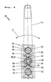
- Fig. 1 eine auseinandergezogene Teil-Seitenansicht, teilweise im Längsschnitt, der Bestandteile einer Drehhandhabe,
- Fig. 2a eine Draufsicht auf eine Abdeckplatte,
- Fig. 2b einen Mitten-Querschnitt durch die Abdeckplatte von Fig. 2a,
- Fig. 2c einen Mitten-Längsschnitt durch die Abdeckplatte von Fig. 2a und
- Fig. 3 eine Druntersicht unter eine montierte Drehhandhabe.
- 1 is an exploded partial side view, partly in longitudinal section, of the components of a rotary handle,
- 2a is a plan view of a cover plate,
- 2b is a central cross section through the cover plate of Fig. 2a,
- Fig. 2c shows a central longitudinal section through the cover plate of Fig. 2a and
- Fig. 3 is a bottom view under an assembled rotary handle.
Ein in seiner Gesamtheit mit 10 bezeichneter Fenstergriff hat, wie aus Fig. 1 ersichtlich ist, einen Griffhals 12 mit einem daran winkelig anschließenden Griff-Hauptteil 14, der innen bzw. unten Fingermulden 15 haben kann. Der Griffhals 12 endet mit einer Schulter 16 und einem daran anschließenden Ansatz 18, der einen Bund 19, eine Ringnut 20 und einen Wulst 21 mit einer End-Fase 22 hat. Achsparallel sind insbesondere vier Schlitze 24 vom Ende des Ansatzes 18 nach oben so geführt, daß sie vor der Schulter 16 enden. An denselben Umfangsstellen des Ansatzes 18 hat dieser, vom Bund 19 ausgehend, als Kerben ausgebildete Rastausnehmungen 26, welche den Flachseiten eines gestrichelt angedeuteten Vierkantloches 28 zugeordnet sind. Dieses nimmt einen Betätigungs-Vierkant B formschlüssig auf, sobald der Griff 10 montiert ist.A window handle designated in its entirety with 10, as can be seen from FIG. 1, has a
Eine mit 30 bezeichnete Anschlagplatte hat eine ebene Deckfläche 31 und an einer dazu parallelen Bodenfläche abstehende Nocken 32, die von Schraublöchern 33 durchsetzt sind. Zentrisch ist eine Buchse 34 vorhanden, in deren Innenumfang Federn 35 mit Nasen 36 einfallen können (Fig. 3). Die Anschlagplatte bildet einen Hohlkörper mit einem Kammersystem, das Längsstege 52 mit schrägen Versteifungen und Stützen 54 aufweist, an welche sich die zur Mittelachse hin gewölbten Stege der Federn 35 anschließen.A stop plate designated by 30 has a
Aus Fig. 1 ist ersichtlich, daß sich die Buchse 34 der Anschlagplatte 30 in Axialrichtung A mit einem Lagerring 37 und einer Aussparung 38 fortsetzt.From Fig. 1 it can be seen that the
Zwischen dem Griffhals 12 und der Anschlagplatte 30 befindet sich eine Abdeckplatte 40, deren Aufbau vor allem aus Fig. 2a, 2b, 2c ersichtlich ist. Sie hat einen umlaufenden Rand 42 und ist einstückig mit einer Feder 44, die von zwei Bögen 46 beiderseits eines Durchgangsloches 48 nahe den Längsseiten 50 gebildet ist. Mit ihrem Scheitel stützen sich die Bögen 46 nach der Montage des Griffes 10 an der Schulter 16 des Griffhalses 12 ab.Between the
Das Durchgangsloch 48 erlaubt es, den Ansatz 18 des Griffhalses 12 hindurchzustecken, um ihn mit der Anschlagplatte 30 zu verrasten. Die Einführ-Fase 22 erleichtert es, die sich dabei an den Schlitzen 24 zusammendrückenden Wulst-Teile 21 in die Buchse 34 einzuführen, bis der Lagerring 37 in der Ringnut 20 verrastet ist. Hinterschneidungen sind hierzu im allgemeinen nicht erforderlich, können aber den sicheren Sitz des Ansatzes 18 in der Buchse 34 der Anschlagplatte 30 unterstützen.The through
Aus der Druntersicht von Fig. 3 entnimmt man, daß die Nasen 36 der Federn 35 den eingerasteten Ansatz 18 mit den Kerben 26 auch in Umfangsrichtung U festlegen. Die Rastelemente, 26, 36 bewirken im gezeichneten Ausführungsbeispiel eine 90°-Rastung, so daß der Griff-Hauptteil 14 in bezug auf die Anschlagplatte 30 nach oben oder unten sowie nach links oder rechts rastend gestellt werden kann. - Als Variante zu Fig. 1 hat der in Fig. 3 dargestellte Griff-Hauptteil 14 unten bzw. innen keine Fingermulden.From the bottom view of FIG. 3 it can be seen that the
In den Rahmen der Erfindung fallen noch weitere Abwandlungen. Beispielsweise können auch an den Längsseiten der Anschlagplatte 30 oder in anderer Winkelstellung zu der Lagerbuchse 34 Federn mit Rastnasen vorhanden sein. Möglich ist es ferner, an der Abdeckplatte 40 eine Feder 44 anderer Gestaltung vorzusehen, beispielsweise eine umlaufende Wellfeder oder Federbögen auch an den Schmalseiten, gegebenenfalls in Form von Rastnasen, welche in entsprechende Vertiefungen in der Schulter 16 des Griffhalses 12 einfallen können.Further modifications fall within the scope of the invention. For example, springs with locking lugs can also be present on the long sides of the
Claims (16)
Priority Applications (1)
| Application Number | Priority Date | Filing Date | Title |
|---|---|---|---|
| AT90110441T ATE83289T1 (en) | 1989-07-07 | 1990-06-01 | ROTARY HANDLE. |
Applications Claiming Priority (2)
| Application Number | Priority Date | Filing Date | Title |
|---|---|---|---|
| DE8908282U | 1989-07-07 | ||
| DE8908282U DE8908282U1 (en) | 1989-07-07 | 1989-07-07 | Rotating handle |
Publications (3)
| Publication Number | Publication Date |
|---|---|
| EP0406566A1 EP0406566A1 (en) | 1991-01-09 |
| EP0406566B1 true EP0406566B1 (en) | 1992-12-09 |
| EP0406566B2 EP0406566B2 (en) | 1996-08-14 |
Family
ID=6840862
Family Applications (1)
| Application Number | Title | Priority Date | Filing Date |
|---|---|---|---|
| EP90110441A Expired - Lifetime EP0406566B2 (en) | 1989-07-07 | 1990-06-01 | Mechanism for manipulation of rotation |
Country Status (3)
| Country | Link |
|---|---|
| EP (1) | EP0406566B2 (en) |
| AT (1) | ATE83289T1 (en) |
| DE (2) | DE8908282U1 (en) |
Cited By (5)
| Publication number | Priority date | Publication date | Assignee | Title |
|---|---|---|---|---|
| EP0568896A2 (en) * | 1992-05-05 | 1993-11-10 | Siegenia-Frank Kg | Door or window handle |
| AU705705B2 (en) * | 1994-03-11 | 1999-05-27 | Black & Decker Incorporated | Door handle mounting assembly |
| EP1152106A1 (en) | 2000-05-04 | 2001-11-07 | Hoppe AG | Actuating handle |
| EP2034110A2 (en) | 2007-09-07 | 2009-03-11 | Dorma GmbH + Co. KG | Safety device |
| EP2034109A2 (en) | 2007-09-07 | 2009-03-11 | DORMA GmbH + Co. KG | Safety device |
Families Citing this family (13)
| Publication number | Priority date | Publication date | Assignee | Title |
|---|---|---|---|---|
| DE3935074A1 (en) * | 1989-10-20 | 1991-04-25 | Mayer & Co | Cover plate for vehicle door or window lock - is held in place round handle by spring tags which grip boss on door fitting |
| DE9418068U1 (en) * | 1994-11-11 | 1995-01-12 | Hoppe AG, 35260 Stadtallendorf | Gear handle |
| DE29511547U1 (en) * | 1995-07-19 | 1996-11-21 | Hewi Heinrich Wilke Gmbh, 34454 Arolsen | Device for axially immovable, releasable attachment of a handle to a bearing part, in particular for door handles, window handles or the like. |
| DE29602822U1 (en) * | 1996-02-17 | 1996-05-15 | Bks Gmbh, 42549 Velbert | Bearing arrangement with plain bearing for a lever handle |
| DE20314279U1 (en) * | 2003-09-12 | 2003-11-13 | Hoppe AG, 35260 Stadtallendorf | handle assembly |
| DE202004019465U1 (en) | 2004-12-15 | 2005-04-21 | Hoppe Ag, St Martin | Actuating handle |
| DE102005000090A1 (en) * | 2005-07-19 | 2007-01-25 | Aug. Winkhaus Gmbh & Co. Kg | Key and lock cylinder for a key |
| DE102006009371A1 (en) | 2006-03-01 | 2007-09-06 | Hoppe Ag | Latching means and use in actuating handles |
| FR2928677A1 (en) * | 2008-03-11 | 2009-09-18 | Lir Packaging | Handle assembly for door, has handle fixed to handle support using clip, where handle has circular clipping tabs cooperating with complementary clipping units of sub-rosette so as to permit rotation of handle |
| EP2998469B1 (en) * | 2014-09-22 | 2018-11-07 | dormakaba Deutschland GmbH | Fitting for a building door |
| IT201800004490A1 (en) * | 2018-04-13 | 2019-10-13 | MANUAL CONTROL DEVICE FOR A LOCK OF A WINDOW | |
| IT201800004474A1 (en) * | 2018-04-13 | 2019-10-13 | MANUAL CONTROL DEVICE FOR A LOCK OF A WINDOW | |
| GB2624021A (en) * | 2022-11-04 | 2024-05-08 | Debar Ltd | Door handle assembly |
Family Cites Families (11)
| Publication number | Priority date | Publication date | Assignee | Title |
|---|---|---|---|---|
| GB191300022A (en) * | 1913-01-01 | 1913-11-20 | Herbert Lee Robinson | An Improved Device for Containing, Delivering and Moistening Postage Stamps and the like. |
| GB221913A (en) * | 1923-07-17 | 1924-09-25 | John Flesher Newsom | Improvements in the process of ore dredging |
| FR1315424A (en) * | 1962-02-17 | 1963-01-18 | Retaining ring for rotary shafts or the like | |
| GB1428042A (en) * | 1973-06-01 | 1976-03-17 | Rizzotto G | Rotatable latch actuators |
| GB1465910A (en) * | 1973-12-19 | 1977-03-02 | Dortend Ltd | Latch or lock set and method of manufacture thereof |
| US4012806A (en) * | 1975-04-30 | 1977-03-22 | The Grigoleit Company | Knob with deformable web |
| US4014573A (en) * | 1975-11-07 | 1977-03-29 | Schlage Lock Company | Thumbturn and assembly and method of providing a thumbturn |
| GB1534879A (en) * | 1976-05-07 | 1978-12-06 | Cartwright & Co Ltd R | Door handles |
| FR2466592A1 (en) * | 1979-10-01 | 1981-04-10 | Bezault Sa | Mounting of handle to door bearing plate - prevents axial play between handle and plate by retaining flanged metal bearing ring between them |
| FR2508527B1 (en) * | 1981-06-29 | 1986-04-11 | Bezault Sa | IMPROVEMENT IN CRIMPING OF STANDS ON DOORS OR DOOR PLATES |
| US4648643A (en) * | 1984-03-26 | 1987-03-10 | Schlage Lock Company | Retrofit lever assembly for a door knob |
-
1989
- 1989-07-07 DE DE8908282U patent/DE8908282U1/en not_active Expired - Lifetime
-
1990
- 1990-06-01 DE DE9090110441T patent/DE59000570D1/en not_active Expired - Fee Related
- 1990-06-01 AT AT90110441T patent/ATE83289T1/en not_active IP Right Cessation
- 1990-06-01 EP EP90110441A patent/EP0406566B2/en not_active Expired - Lifetime
Cited By (6)
| Publication number | Priority date | Publication date | Assignee | Title |
|---|---|---|---|---|
| EP0568896A2 (en) * | 1992-05-05 | 1993-11-10 | Siegenia-Frank Kg | Door or window handle |
| AU705705B2 (en) * | 1994-03-11 | 1999-05-27 | Black & Decker Incorporated | Door handle mounting assembly |
| EP1152106A1 (en) | 2000-05-04 | 2001-11-07 | Hoppe AG | Actuating handle |
| EP2034110A2 (en) | 2007-09-07 | 2009-03-11 | Dorma GmbH + Co. KG | Safety device |
| EP2034109A2 (en) | 2007-09-07 | 2009-03-11 | DORMA GmbH + Co. KG | Safety device |
| DE102008044934A1 (en) | 2007-09-07 | 2009-03-12 | Dorma Gmbh + Co. Kg | safety device |
Also Published As
| Publication number | Publication date |
|---|---|
| EP0406566B2 (en) | 1996-08-14 |
| DE59000570D1 (en) | 1993-01-21 |
| ATE83289T1 (en) | 1992-12-15 |
| EP0406566A1 (en) | 1991-01-09 |
| DE8908282U1 (en) | 1990-05-03 |
Similar Documents
| Publication | Publication Date | Title |
|---|---|---|
| EP0406566B1 (en) | Mechanism for manipulation of rotation | |
| DE60223868T2 (en) | Connecting device for a button | |
| DE2754518A1 (en) | HIGH PERFORMANCE CUTTING TOOL WITH RETRACTABLE BLADE | |
| EP3318368B1 (en) | Releasable handle fixing coupling for working units | |
| AT2249U1 (en) | HAND STAMP WITH SELF-COLORING DEVICE | |
| DE2844578C2 (en) | Command button | |
| DE20301113U1 (en) | combination lock | |
| EP2438842B1 (en) | Connection piece with catch element | |
| DE2004292A1 (en) | Quick release fastener | |
| DE69411534T2 (en) | Retractable rotary knob | |
| EP0859898B1 (en) | Door lock which can be used in right-hand or left-hand mode | |
| DE19908259A1 (en) | Wiper mop plate has cardan linked holder, sleeve, long handle, fork, tubular holder, thrust pieces and turning axes | |
| EP3741937B1 (en) | Folding lock | |
| EP0215295A1 (en) | Coupling for a detachable connection between a head and a handle of a dental handpiece | |
| EP0417032B1 (en) | Mechanism for manipulation of windows, doors or similar | |
| EP1385076B1 (en) | Rotary switch assembly | |
| DE2949042A1 (en) | FASTENING ARRANGEMENT FOR A REAR VIEW MIRROR | |
| DE3426050C2 (en) | ||
| CH625572A5 (en) | ||
| EP0540845A1 (en) | Pivoting connection between the individual members of a folding rulers | |
| DE3506121C2 (en) | ||
| DE3605301C2 (en) | ||
| DE2442645C3 (en) | Collar plug-in device, in particular round plug-in device | |
| DE3312770C2 (en) | Writing implement | |
| DE20004018U1 (en) | Twist grip |
Legal Events
| Date | Code | Title | Description |
|---|---|---|---|
| PUAI | Public reference made under article 153(3) epc to a published international application that has entered the european phase |
Free format text: ORIGINAL CODE: 0009012 |
|
| AK | Designated contracting states |
Kind code of ref document: A1 Designated state(s): AT CH DE FR GB IT LI NL |
|
| 17P | Request for examination filed |
Effective date: 19901122 |
|
| 17Q | First examination report despatched |
Effective date: 19911216 |
|
| GRAA | (expected) grant |
Free format text: ORIGINAL CODE: 0009210 |
|
| AK | Designated contracting states |
Kind code of ref document: B1 Designated state(s): AT CH DE FR GB IT LI NL |
|
| REF | Corresponds to: |
Ref document number: 83289 Country of ref document: AT Date of ref document: 19921215 Kind code of ref document: T |
|
| REF | Corresponds to: |
Ref document number: 59000570 Country of ref document: DE Date of ref document: 19930121 |
|
| ET | Fr: translation filed | ||
| ITF | It: translation for a ep patent filed | ||
| GBT | Gb: translation of ep patent filed (gb section 77(6)(a)/1977) |
Effective date: 19930218 |
|
| PLBI | Opposition filed |
Free format text: ORIGINAL CODE: 0009260 |
|
| PLBI | Opposition filed |
Free format text: ORIGINAL CODE: 0009260 |
|
| 26 | Opposition filed |
Opponent name: SIEGENIA-FRANK KG Effective date: 19930825 |
|
| 26 | Opposition filed |
Opponent name: ROTO FRANK AG Effective date: 19930908 Opponent name: SIEGENIA-FRANK KG Effective date: 19930825 |
|
| NLR1 | Nl: opposition has been filed with the epo |
Opponent name: SIEGENIA-FRANK KG |
|
| NLR1 | Nl: opposition has been filed with the epo |
Opponent name: ROTO FRANK AG |
|
| PLAB | Opposition data, opponent's data or that of the opponent's representative modified |
Free format text: ORIGINAL CODE: 0009299OPPO |
|
| R26 | Opposition filed (corrected) |
Opponent name: SIEGENIA-FRANK KG * 930908 ROTO FRANK AG Effective date: 19930825 |
|
| PLAW | Interlocutory decision in opposition |
Free format text: ORIGINAL CODE: EPIDOS IDOP |
|
| PLAW | Interlocutory decision in opposition |
Free format text: ORIGINAL CODE: EPIDOS IDOP |
|
| PLAW | Interlocutory decision in opposition |
Free format text: ORIGINAL CODE: EPIDOS IDOP |
|
| PUAH | Patent maintained in amended form |
Free format text: ORIGINAL CODE: 0009272 |
|
| STAA | Information on the status of an ep patent application or granted ep patent |
Free format text: STATUS: PATENT MAINTAINED AS AMENDED |
|
| RAP2 | Party data changed (patent owner data changed or rights of a patent transferred) |
Owner name: HOPPE AG |
|
| 27A | Patent maintained in amended form |
Effective date: 19960814 |
|
| AK | Designated contracting states |
Kind code of ref document: B2 Designated state(s): AT CH DE FR GB IT LI NL |
|
| REG | Reference to a national code |
Ref country code: CH Ref legal event code: AEN Free format text: AUFRECHTERHALTUNG DES PATENTES IN GEAENDERTER FORM |
|
| ET3 | Fr: translation filed ** decision concerning opposition | ||
| NLR2 | Nl: decision of opposition | ||
| NLT2 | Nl: modifications (of names), taken from the european patent patent bulletin |
Owner name: HOPPE AG |
|
| GBTA | Gb: translation of amended ep patent filed (gb section 77(6)(b)/1977) |
Effective date: 19960918 |
|
| ITF | It: translation for a ep patent filed | ||
| NLR3 | Nl: receipt of modified translations in the netherlands language after an opposition procedure | ||
| REG | Reference to a national code |
Ref country code: GB Ref legal event code: IF02 |
|
| PGFP | Annual fee paid to national office [announced via postgrant information from national office to epo] |
Ref country code: CH Payment date: 20030520 Year of fee payment: 14 |
|
| PGFP | Annual fee paid to national office [announced via postgrant information from national office to epo] |
Ref country code: NL Payment date: 20030530 Year of fee payment: 14 Ref country code: GB Payment date: 20030530 Year of fee payment: 14 |
|
| PGFP | Annual fee paid to national office [announced via postgrant information from national office to epo] |
Ref country code: DE Payment date: 20030603 Year of fee payment: 14 |
|
| PG25 | Lapsed in a contracting state [announced via postgrant information from national office to epo] |
Ref country code: GB Free format text: LAPSE BECAUSE OF NON-PAYMENT OF DUE FEES Effective date: 20040601 |
|
| PG25 | Lapsed in a contracting state [announced via postgrant information from national office to epo] |
Ref country code: LI Free format text: LAPSE BECAUSE OF NON-PAYMENT OF DUE FEES Effective date: 20040630 Ref country code: CH Free format text: LAPSE BECAUSE OF NON-PAYMENT OF DUE FEES Effective date: 20040630 |
|
| PG25 | Lapsed in a contracting state [announced via postgrant information from national office to epo] |
Ref country code: NL Free format text: LAPSE BECAUSE OF NON-PAYMENT OF DUE FEES Effective date: 20050101 Ref country code: DE Free format text: LAPSE BECAUSE OF NON-PAYMENT OF DUE FEES Effective date: 20050101 |
|
| GBPC | Gb: european patent ceased through non-payment of renewal fee | ||
| REG | Reference to a national code |
Ref country code: CH Ref legal event code: PL |
|
| NLV4 | Nl: lapsed or anulled due to non-payment of the annual fee |
Effective date: 20050101 |
|
| PG25 | Lapsed in a contracting state [announced via postgrant information from national office to epo] |
Ref country code: IT Free format text: LAPSE BECAUSE OF NON-PAYMENT OF DUE FEES Effective date: 20050601 |
|
| PGFP | Annual fee paid to national office [announced via postgrant information from national office to epo] |
Ref country code: AT Payment date: 20070618 Year of fee payment: 18 |
|
| PGFP | Annual fee paid to national office [announced via postgrant information from national office to epo] |
Ref country code: FR Payment date: 20070615 Year of fee payment: 18 |
|
| REG | Reference to a national code |
Ref country code: FR Ref legal event code: ST Effective date: 20090228 |
|
| PG25 | Lapsed in a contracting state [announced via postgrant information from national office to epo] |
Ref country code: AT Free format text: LAPSE BECAUSE OF NON-PAYMENT OF DUE FEES Effective date: 20080601 |
|
| PG25 | Lapsed in a contracting state [announced via postgrant information from national office to epo] |
Ref country code: FR Free format text: LAPSE BECAUSE OF NON-PAYMENT OF DUE FEES Effective date: 20080630 |