EP0405880A2 - Verfahren und Apparat zum Anbringen einer Reflexionshülse an einem kegelförmigen Verkehrszeichen - Google Patents
Verfahren und Apparat zum Anbringen einer Reflexionshülse an einem kegelförmigen Verkehrszeichen Download PDFInfo
- Publication number
- EP0405880A2 EP0405880A2 EP90306913A EP90306913A EP0405880A2 EP 0405880 A2 EP0405880 A2 EP 0405880A2 EP 90306913 A EP90306913 A EP 90306913A EP 90306913 A EP90306913 A EP 90306913A EP 0405880 A2 EP0405880 A2 EP 0405880A2
- Authority
- EP
- European Patent Office
- Prior art keywords
- traffic cone
- sleeve
- mandrel
- platform
- reflective
- Prior art date
- Legal status (The legal status is an assumption and is not a legal conclusion. Google has not performed a legal analysis and makes no representation as to the accuracy of the status listed.)
- Granted
Links
Images


Classifications
-
- B—PERFORMING OPERATIONS; TRANSPORTING
- B65—CONVEYING; PACKING; STORING; HANDLING THIN OR FILAMENTARY MATERIAL
- B65H—HANDLING THIN OR FILAMENTARY MATERIAL, e.g. SHEETS, WEBS, CABLES
- B65H75/00—Storing webs, tapes, or filamentary material, e.g. on reels
- B65H75/50—Methods of making reels, bobbins, cop tubes, or the like by working an unspecified material, or several materials
-
- B—PERFORMING OPERATIONS; TRANSPORTING
- B65—CONVEYING; PACKING; STORING; HANDLING THIN OR FILAMENTARY MATERIAL
- B65H—HANDLING THIN OR FILAMENTARY MATERIAL, e.g. SHEETS, WEBS, CABLES
- B65H81/00—Methods, apparatus, or devices for covering or wrapping cores by winding webs, tapes, or filamentary material, not otherwise provided for
- B65H81/06—Covering or wrapping elongated cores
-
- E—FIXED CONSTRUCTIONS
- E01—CONSTRUCTION OF ROADS, RAILWAYS, OR BRIDGES
- E01F—ADDITIONAL WORK, SUCH AS EQUIPPING ROADS OR THE CONSTRUCTION OF PLATFORMS, HELICOPTER LANDING STAGES, SIGNS, SNOW FENCES, OR THE LIKE
- E01F9/00—Arrangement of road signs or traffic signals; Arrangements for enforcing caution
- E01F9/60—Upright bodies, e.g. marker posts or bollards; Supports for road signs
- E01F9/623—Upright bodies, e.g. marker posts or bollards; Supports for road signs characterised by form or by structural features, e.g. for enabling displacement or deflection
- E01F9/654—Upright bodies, e.g. marker posts or bollards; Supports for road signs characterised by form or by structural features, e.g. for enabling displacement or deflection in the form of three-dimensional bodies, e.g. cones; capable of assuming three-dimensional form, e.g. by inflation or erection to form a geometric body
-
- E—FIXED CONSTRUCTIONS
- E01—CONSTRUCTION OF ROADS, RAILWAYS, OR BRIDGES
- E01F—ADDITIONAL WORK, SUCH AS EQUIPPING ROADS OR THE CONSTRUCTION OF PLATFORMS, HELICOPTER LANDING STAGES, SIGNS, SNOW FENCES, OR THE LIKE
- E01F9/00—Arrangement of road signs or traffic signals; Arrangements for enforcing caution
- E01F9/60—Upright bodies, e.g. marker posts or bollards; Supports for road signs
- E01F9/688—Free-standing bodies
-
- Y—GENERAL TAGGING OF NEW TECHNOLOGICAL DEVELOPMENTS; GENERAL TAGGING OF CROSS-SECTIONAL TECHNOLOGIES SPANNING OVER SEVERAL SECTIONS OF THE IPC; TECHNICAL SUBJECTS COVERED BY FORMER USPC CROSS-REFERENCE ART COLLECTIONS [XRACs] AND DIGESTS
- Y10—TECHNICAL SUBJECTS COVERED BY FORMER USPC
- Y10T—TECHNICAL SUBJECTS COVERED BY FORMER US CLASSIFICATION
- Y10T156/00—Adhesive bonding and miscellaneous chemical manufacture
- Y10T156/10—Methods of surface bonding and/or assembly therefor
- Y10T156/1002—Methods of surface bonding and/or assembly therefor with permanent bending or reshaping or surface deformation of self sustaining lamina
- Y10T156/1028—Methods of surface bonding and/or assembly therefor with permanent bending or reshaping or surface deformation of self sustaining lamina by bending, drawing or stretch forming sheet to assume shape of configured lamina while in contact therewith
- Y10T156/1033—Flexible sheet to cylinder lamina
Definitions
- the present invention relates to methods and apparatus for adhesively applying a reflective sleeve to a traffic cone.
- traffic cone includes, but is not limited to, bodies integrally formed from a flexible polymeric material and having a base portion for supporting an upright, generally conical or cylindrical member.
- a six inch wide reflective band may be placed nominally three inches from the top of the traffic cone and a four inch wide reflective sleeve placed two inches below the six inch band.
- the reflective bands must be located within a tolerance of ⁇ 0.125 inches. Such reflective sheeting may be applied manually, but such a process is slow and therefore expensive and requires considerable skill if accuracy is desired.
- U.K. Patent No. 2,096,214 A entitled “Portable Road Markers”, commonly assigned to the assignee of the present invention discloses a method and apparatus for applying a narrow pressure sensitive adhesive tape having a reflective surface opposite the adhesive surface, to a traffic cone or "bollard".
- the method provides for rotating the tape applying apparatus relative to the traffic cone and means for severing the tape when a sufficient length has been applied to the traffic cone.
- Means are also provided so that the traffic cone and the tape applying apparatus may be axially shifted relative to each other so that the tape may be applied in a generally helical fashion, although it is contemplated that the tape may be applied in one or more concentric bands.
- the U.K. '214 patent discusses the difficulties in applying a preformed adjustable sleeve of adhesively secured reflective material to a precise location on a traffic cone.
- the present invention provides a method and apparatus for adhesively applying a reflective sleeve to a traffic cone.
- the method for applying a reflective sleeve to a traffic cone comprises the steps of: providing a traffic cone having a longitudinal axis; providing a reflective sleeve having one major surface coated with a pressure sensitive adhesive and having spaced end edges; positioning the traffic cone adjacent to one end edge of the sleeve with the nearest tangent line of the traffic cone aligned with but spaced from an end edge of the sleeve; placing the adjacent end edge of the sleeve in contact with the traffic cone at the nearest tangent line; rotating the traffic cone about its longitudinal axis to wind up the sleeve on the traffic cone; and removing the traffic cone with the reflective sleeve from the mandrel.
- apparatus for practicing the above method comprising: a frame; a mandrel having a longitudinal axis mounted on said frame for receiving the traffic cone and including means for securing the traffic cone on said mandrel; a platform mounted on said frame for supporting the reflective sleeve with a pressure sensitive adhesive surface of the reflective sleeve exposed; means mounted on said frame for shifting said mandrel with the traffic cone secured thereon between a first position and a second position so that a tangent line of the traffic cone nearest to said platform is parallel to and spaced from an end edge of the sleeve; means mounted on said frame for shifting said platform between a first position to a second position with said mandrel in said second position to place the pressure sensitive adhesive surface of the adhesive sleeve along said end edge thereof in contact with the traffic cone at the nearest tangent line; and means mounted on said frame for rotating said mandrel about said longitudinal axis to wind the sleeve onto the traffic cone.
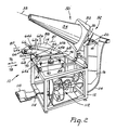
- the apparatus 10 comprises frame 12 for supporting the remainder of the apparatus.
- Platform 14 is horizontally mounted on the frame and will explained in greater detail hereinafter.
- Upwardly extending brackets 16 and 18 are mounted on the back edge of frame 12.
- Rod 20 extends between brackets 16 and 18 and is pivotally mounted thereon.
- Double acting first pneumatic cylinder 22 is connected at one end to frame 12 and the shaft thereof is connected by crank arm 24 to rod 20.
- Pneumatic motor 26 is mounted on rod 20.
- Bearing 30 is mounted on motor 26.
- Mandrel 32 includes longitudinal axis 33 and is rotatively supported by bearing 30 and connected to motor 26 to extend over platform 14.
- Mandrel 32 includes stationary portion 34 and adjustable portion 36 which is capable of reciprocal movement along axis 33 with respect to the stationary portion.
- the adjustable portion is biased by a spring or the like (not shown) outwardly from the stationary portion with sufficient force to maintain the position shown in Figure 1.
- Extension of the shaft of pneumatic cylinder 22 in direction 38 will cause rotation of rod 20, motor 26, bearing 30 and mandrel 32 in direction 40 about an axis 41 extending through rod 20 and generally perpendicular to the longitudinal axis 33 of the mandrel.
- Retraction of the shaft in opposite direction 42 will cause rotation of rod 20 and mandrel 32 in opposite rotational direction 44 about axis 41.
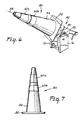
- traffic cone 50 includes base 52 and upright member 54, both shown generally frusto conical in shape, although the present invention may also be employed with traffic cones having a generally cylindrical upright member and therefore would require a generally cylindrical mandrel.
- traffic cone 50 is constructed of a monolithic molded polymeric material such as plasticized polyvinyl chloride or polyolefins such as polyethylene.
- the following are examples of commercially available traffic cones which may be used with the present invention: Model 28 PVCS available from Work Area Protection Corp. of St. Charles, Illinois; Model TC-28FL available from Service and Materials Co. of Elwood, Indiana; Model 2850-7 available from the Lakeside Plastics Inc. of Oshkosh, Wisconsin.
- Traffic cone 50 may be mounted on the apparatus by mandrel 32 by sliding the traffic cone on the mandrel until the interior of the traffic cone encounters stationary portion 34.
- stationary portion 34 is adapted to frictionally grip traffic cone 50 to secure it thereon.
- a concentric ring 56 of Safety-Walk tm brand sheeting available from Minnesota Mining and Manufacturing Co. of St. Paul, Minnesota may be adhered to the stationary portion for gripping the traffic cone when pushed onto the mandrel. The frictional sheeting provides sufficient force to hold the traffic cone in position while the reflective sleeves are applied, yet permits easy manual removal.
- Both portions 34, 36 of mandrel 32 are tapered at the nominal taper of the traffic cone to be used with the apparatus.
- adjustable portion 36 is biased to an extreme position away from stationary portion 34, as shown in Figure 1. Due to the large tolerances inherent in the manufacture of traffic cones as well as the deformable nature of the polymeric material normally used to construct traffic cones, the internal taper of individual traffic cones may not match the nominal taper of mandrel 32. This results in misplacement of the traffic cone on the mandrel and deformation of the traffic cone in areas that the reflective sleeves are to be applied. In either case, the reflective sleeves may not be accurately or reliably applied to the traffic cone.
- the illustrated mandrel 32 is constructed to accommodate the variations in traffic cones due to the reciprocal movement of adjustable portion 36 with respect to stationary portion 34. If the taper of a particular traffic cone is less than the nominal taper of the mandrel, adjustable portion 36 of the mandrel will be retracted slightly as the traffic cone is slid onto the mandrel and contacts stationary portion 34. If a traffic cone has a taper that is greater than nominal, adjustable portion 36 will be pushed closer to stationary portion 34 of the mandrel.
- the mandrel securely holds the traffic cone in a desired location relative to the platform and each of the portions 34, 36 of mandrel 32 underlay and support the segments of traffic cone 50 on which the reflective sleeves are to be applied.
- a mandrel may be constructed with more than two portions to more closely conform to the actual taper of individual traffic cones. This may also be desirable if more than two reflective sleeves are to be applied to a traffic cone.
- a pair of sleeves 60a and 60b are shown for application to the traffic cone. Although two sleeves are illustrated, the method and apparatus of the present invention are equally adapted to apply one or more than two sleeves to a traffic cone.
- the sleeves although varying in dimensions, each include longitudinal edges 62a, 62b and spaced end edges 64a, 64b, respectively. If the upright member of the traffic cone is frusto conical in shape, then the longitudinal edges of the reflective sleeves will be arcuate and concentric to accommodate the variation in the circumference of the upright member along its length. If the upright member is cylindrical, then the longitudinal edges are linear and parallel and all sleeves would be the same length.
- One major surface of the sleeves includes a reflective material or coating and the opposite major surface is coated with a pressure sensitive adhesive.
- Model Nos. 3840 and 3810 brand reflective sheeting available from Minnesota Mining and Manufacturing Co. of St. Paul, Minnesota are examples of reflective sheeting that may be used with the traffic cones listed above, as well as others, in the process and with the apparatus of this invention.
- the location means includes stops 66.
- the stops contact the longitudinal and end edges of the reflective sleeves 60a, 60b as shown to precisely determine the location of the sleeves with respect to the platform and specifically to align a pair of end edges 64a, 64b of each sleeve along a line 68 as shown in Figure 2.
- a cushion or resilient strip 70 is mounted on the platform to support end edges 64a, 64b of sleeves 60a, 60b as the sleeves are applied to the traffic cone, as will be explained in greater detail hereinafter.
- cushion 70 is mounted within a recessed groove (not shown) formed in the platform so that the upper surface of the cushion is generally flush with the platform.
- Stops 66 may be made adjustable, such by threadedly securing them to the platform and by providing alternate threaded holes (not shown) in the platform so that the stops may be resecured to the platform in different locations to accommodate sleeves of different dimensions. Further, stops 66 may be eccentrically mounted to the platform so that rotation of a stop about the threaded connection enables a finer adjustment in the location of sleeves 60a, 60b with respect to the platform. Alternatively, recesses (not shown) could be formed in the platform for receipt of the reflective sleeves.
- the position of platform 14 relative to frame 12 and mandrel 32 may be adjusted.
- the adjustment of the platform is accomplished by slidingly mounting the platform on rails 72 and 74, enabling movement of the platform in opposite directions 76 and 78 parallel to line 68.
- Platform 14 may be secured in a desired longitudinal position relative to the mandrel by screws 82 which are threadedly engaged with the platform and may be tightened to contact rails 72 and 74.
- screws 84 are provided and threadedly engaged with the platform so that the position of the platform may be adjusted vertically with respect to the frame and secured to rails 72 and 74 in a desired position by screws 84.
- mandrel 32 and traffic cone 50 have been lowered from the first position shown in Figures 1 and 2 to a second position.
- the tangent line 86 of the portion of upright member 54 of traffic cone 50 closest to end edges 64a, 64b of the reflective sleeves 60a, 60b respectively is parallel to and spaced therefrom.
- Longitudinal axis 33 of the mandrel is inclined downwardly with respect to the platform at the angle of taper of the traffic cone. If traffic cone 50 included a cylindrical upright member (not shown), longitudinal axis 33 of the mandrel and tangent line 86 of the traffic cone would be parallel to each other and to the line 68 on the platform.
- Means are provided to shift the platform between first and second positions in order to place the end edge of the reflective sleeve in contact with the traffic cone at the nearest tangent point of the traffic cone.
- the platform may be shifted in any desired manner, in the illustrated embodiment, the platform is rotated about an axis 87 generally parallel to the tangent line 68 of the traffic cone when the traffic cone and the mandrel are in their second position.
- Axis 87 is also generally perpendicular to axis 41 about which the mandrel rotates between its first and second positions.
- one edge 88 of the platform 14 is hingedly mounted to frame 12 to form axis 87.
- Double acting second pneumatic cylinder 90 is mounted with one end mounted on frame 12 and the other end connected to platform 14 spaced from the hinged connection 88.
- second pneumatic cylinder 90 By activating second pneumatic cylinder 90 and extending its shaft in direction 92, platform 14 rotates upwardly in rotational direction 94 from its first position to its second, upper position, shown in Figure 4. Retraction of the shaft of the second pneumatic cylinder 90 in direction 96 will rotate platform 14 in opposite rotational direction 98 back to its first position.
- edges 64a, 64b of the reflective sleeves aligned with line 68 on the platform is determined so that when the platform is rotated to its second position, the edges 64a, 64b and the pressure sensitive adhesive surface of the sleeves are brought into contact with the tangent line 86 of the traffic cone.
- platform 14 may be constructed so that it may be raised vertically, eliminating the hinged connection 88.
- traffic cone 50 is rotated in direction 100 about longitudinal axis 33 of mandrel 32 (which is axially aligned with the longitudinal axis of the traffic cone) by activating motor 26 so as to wind the reflective sleeves 60a, 60b about the traffic cone.
- Reflective sleeves 60a, 60b are preferably constructed so that end edges 64a, 64b of each sleeve overlap slightly when applied to the traffic cone to ensure effective adherence thereto.
- the traffic cone is rotated through 11/4 turns to ensure effective application of the reflective sleeves thereto.
- platform 14 is rotated in direction 98 back to its first position by retracting the shaft of the second pneumatic cylinder 90 in direction 96, as shown in Figure 5.
- mandrel 32 may be shifted back to its first position by retracting the shaft of first pneumatic cylinder 22 in direction 44, as shown in Figure 6.
- motor 26 is again activated so as to quickly rotate the mandrel and traffic cone in opposite rotational direction 102. This returns mandrel 32 and motor 26 to their original positions and acts to loosen or dislodge the traffic cone from the mandrel.
- the traffic cone with reflective sleeves 60a, 60b applied may then be easily removed from the mandrel.
- Figure 7 illustrates a traffic cone with the reflective sleeves in place and ready for use.
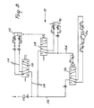
- FIG. 8 is a schematic representation of one such pneumatic circuit 112 for activating and controlling the first and second pneumatic cylinders 22 and 90 and the pneumatic motor 26.
- the pneumatic circuit is connected to a source of compressed air (not shown) which may conveniently be regulated to a pressure of approximately 60 p.s.i.
- the pneumatic circuit 112 includes portions of pneumatic conduit 114 connecting the various components of the circuit, which also includes time delay 116 (such as a PA-40 tm brand time delay available from Numatics Incorporated of Highland,Michigan) and limit switch 118 (neither shown in any of the previous Figures).
- time delay 116 such as a PA-40 tm brand time delay available from Numatics Incorporated of Highland,Michigan
- limit switch 118 either shown in any of the previous Figures.
- the operator of the apparatus depresses foot switch 110, which activates first pneumatic cylinder 22 to shift the mandrel from its first position to its second position.
- the limit switch 118 is mounted on the frame adjacent the brackets 16 and 18.
- the location of the second position of the mandrel is determined by an adjustable screw (not shown) mounted on the mandrel so as to come in contact with limit switch 118 as the mandrel moves in rotational direction 40 and thereby interrupt the supply of compressed air to first pneumatic cylinder 22 and prevent further movement of the mandrel.
- the flow of the compressed air to second pneumatic cylinder 90 is regulated so that the movement of the platform from its first to its second position is achieved only after the mandrel and traffic cone have achieved their second position.
- a second time delay could be utilized in conjunction with foot switch 110 to control movement of the platform.
- time delay 116 initiates the activation of motor 26 in rotational direction 100 only after the platform reaches its second position and places the traffic cone in contact with the pressure sensitive adhesive surface of the reflective sleeves.
- removal of the operators foot from foot switch 110 reactivates the first and the second pneumatic cylinders 22 and 90, respectively, to return the mandrel and the platform to their respective first positions.
- the motor 26 is likewise activated to rotate the mandrel in rotational direction 102, which returns the motor to its initial position. After removal of the traffic cone, the apparatus is in position for receipt of a new traffic cone and reflective sleeves.
- electrical or other known power and control devices may be substituted for the pneumatic devices and pneumatic circuit discussed herein, if desired.
Landscapes
- Engineering & Computer Science (AREA)
- Architecture (AREA)
- Civil Engineering (AREA)
- Structural Engineering (AREA)
- Physics & Mathematics (AREA)
- Geometry (AREA)
- Refuge Islands, Traffic Blockers, Or Guard Fence (AREA)
- Road Signs Or Road Markings (AREA)
- Illuminated Signs And Luminous Advertising (AREA)
Applications Claiming Priority (2)
| Application Number | Priority Date | Filing Date | Title |
|---|---|---|---|
| US371919 | 1989-06-27 | ||
| US07/371,919 US5047107A (en) | 1989-06-27 | 1989-06-27 | Method and apparatus for applying a reflective sleeve to a traffic cone |
Publications (3)
| Publication Number | Publication Date |
|---|---|
| EP0405880A2 true EP0405880A2 (de) | 1991-01-02 |
| EP0405880A3 EP0405880A3 (en) | 1991-01-30 |
| EP0405880B1 EP0405880B1 (de) | 1993-04-21 |
Family
ID=23465957
Family Applications (1)
| Application Number | Title | Priority Date | Filing Date |
|---|---|---|---|
| EP90306913A Expired - Lifetime EP0405880B1 (de) | 1989-06-27 | 1990-06-25 | Verfahren und Apparat zum Anbringen einer Reflexionshülse an einem kegelförmigen Verkehrszeichen |
Country Status (8)
| Country | Link |
|---|---|
| US (1) | US5047107A (de) |
| EP (1) | EP0405880B1 (de) |
| JP (1) | JP2875858B2 (de) |
| AU (1) | AU624719B2 (de) |
| CA (1) | CA2018860A1 (de) |
| DE (1) | DE69001398T2 (de) |
| ES (1) | ES2040057T3 (de) |
| IE (1) | IE64027B1 (de) |
Cited By (3)
| Publication number | Priority date | Publication date | Assignee | Title |
|---|---|---|---|---|
| WO1999024671A1 (en) * | 1997-11-12 | 1999-05-20 | Minnesota Mining And Manufacturing Company | Multicolored retroreflective banded sleeve for a traffic device and method of making |
| WO2005071167A1 (en) * | 2004-01-27 | 2005-08-04 | Simons Theodorus Carolus Josep | Device and method for picking up a pylon |
| KR102440145B1 (ko) * | 2021-06-30 | 2022-09-05 | 주식회사 기성이엔지 | 라바콘 수평식 적재타입 설치 및 회수장치에서의 라바콘 정렬장치 |
Families Citing this family (9)
| Publication number | Priority date | Publication date | Assignee | Title |
|---|---|---|---|---|
| US5451287A (en) * | 1993-12-17 | 1995-09-19 | Minnesota Mining And Manufacturing Company | Machine for wrapping tubular markers with a reflective material |
| US5565055A (en) * | 1995-05-08 | 1996-10-15 | Avery Dennison Corporation | Decoration of articles |
| US5805338A (en) * | 1996-04-10 | 1998-09-08 | Minnesota Minning And Manufacturing Company | Pillowed flexible cube-corner sheeting and methods of manufacture |
| US7165592B1 (en) * | 2002-12-10 | 2007-01-23 | Berran Industrial Group, Inc. | Strip material applicator apparatus |
| US7306398B2 (en) * | 2005-01-06 | 2007-12-11 | Doran Jr John Terrence | Highway marker transfer vehicle |
| US8431232B2 (en) * | 2008-10-30 | 2013-04-30 | Eastman Chemical Company | Aromatic-aliphatic polyester hot melt adhesives for roll-applied labels |
| AU2010217950B2 (en) * | 2009-02-25 | 2014-03-06 | L.B. Foster Company | Composite rail joint end post |
| US8747017B2 (en) * | 2011-04-20 | 2014-06-10 | Stefan Albrecht Dag | Resilient inflatable delineators |
| CN105730802B (zh) * | 2016-04-29 | 2018-08-28 | 福建欣弘机电设备有限公司 | 一种杯子贴纸机 |
Family Cites Families (25)
| Publication number | Priority date | Publication date | Assignee | Title |
|---|---|---|---|---|
| US2081911A (en) * | 1932-12-03 | 1937-06-01 | Burt Co Ltd F N | Applying machine |
| US3455758A (en) * | 1965-12-02 | 1969-07-15 | Horizons Research Inc | Method and apparatus for the manufacture of plastic belts |
| US3616055A (en) * | 1969-05-16 | 1971-10-26 | David H Mages | Optical plate mounter |
| SE351575B (de) * | 1970-09-02 | 1972-12-04 | Polytype Ag | |
| US3709112A (en) * | 1970-09-10 | 1973-01-09 | G Ebinger | Guide picket |
| US3768383A (en) * | 1970-11-03 | 1973-10-30 | Tucker Ass Inc | Directional marker device for automobile roadbeds |
| US3952690A (en) * | 1972-01-18 | 1976-04-27 | Flexicade Ltd. | Highway barricade |
| US3920348A (en) * | 1974-09-09 | 1975-11-18 | Olympic Machine Inc | Traffic lane indicator |
| US3963362A (en) * | 1974-11-27 | 1976-06-15 | Carlisle Corporation | Road marker |
| FR2406696A1 (fr) * | 1977-10-19 | 1979-05-18 | Electroformage Plastiques Cie | Balise de signalisation routiere |
| US4123181A (en) * | 1977-12-02 | 1978-10-31 | Astro Optics Corporation | Roadside barrier marker system |
| US4111581A (en) * | 1978-01-03 | 1978-09-05 | Auriemma Robert S | Highway marker |
| US4197807A (en) * | 1978-06-23 | 1980-04-15 | Campbell Bruce E | Collapsible traffic cone marker |
| US4245922A (en) * | 1979-04-02 | 1981-01-20 | Auriemma Robert S | Traffic delineator post |
| US4221498A (en) * | 1979-05-07 | 1980-09-09 | Astro Optics Corporation | Roadside barrier reflector |
| US4343567A (en) * | 1980-02-27 | 1982-08-10 | Robert D. Cunningham | Self-erecting roadway marking post |
| GB2139116B (en) * | 1980-10-17 | 1985-08-29 | Minnesota Mining & Mfg | Portable road markers |
| GB2096214B (en) * | 1980-10-17 | 1985-08-21 | Minnesota Mining & Mfg | Portable road markers |
| FR2500505A1 (fr) * | 1981-02-24 | 1982-08-27 | Pinoteau Lucien | Balise routiere et son procede d'ancrage |
| US4571118A (en) * | 1984-01-20 | 1986-02-18 | Carsonite International Corporation | Simulated tubular highway safety device |
| FR2516564A1 (fr) * | 1981-11-19 | 1983-05-20 | Cormier Bernard | Element retroreflechissant de signalisation pour voies de circulation |
| US4397710A (en) * | 1982-01-22 | 1983-08-09 | The Meyercord Co. | Machine for applying indicia to tapered or straight cylindrical articles |
| GB2140547A (en) * | 1983-04-22 | 1984-11-28 | John Roach Bichard | Traffic warning signal cone with flashing light |
| JPS60260261A (ja) * | 1984-06-07 | 1985-12-23 | Fuji Xerox Co Ltd | 会議電話用回路 |
| US4573763A (en) * | 1984-12-18 | 1986-03-04 | Eagle Industries, Inc. | Three-dimensional flexible reflectors |
-
1989
- 1989-06-27 US US07/371,919 patent/US5047107A/en not_active Expired - Fee Related
-
1990
- 1990-06-08 IE IE206390A patent/IE64027B1/en not_active IP Right Cessation
- 1990-06-13 CA CA002018860A patent/CA2018860A1/en not_active Abandoned
- 1990-06-13 AU AU57105/90A patent/AU624719B2/en not_active Ceased
- 1990-06-25 DE DE90306913T patent/DE69001398T2/de not_active Expired - Fee Related
- 1990-06-25 ES ES199090306913T patent/ES2040057T3/es not_active Expired - Lifetime
- 1990-06-25 EP EP90306913A patent/EP0405880B1/de not_active Expired - Lifetime
- 1990-06-26 JP JP2165888A patent/JP2875858B2/ja not_active Expired - Lifetime
Cited By (3)
| Publication number | Priority date | Publication date | Assignee | Title |
|---|---|---|---|---|
| WO1999024671A1 (en) * | 1997-11-12 | 1999-05-20 | Minnesota Mining And Manufacturing Company | Multicolored retroreflective banded sleeve for a traffic device and method of making |
| WO2005071167A1 (en) * | 2004-01-27 | 2005-08-04 | Simons Theodorus Carolus Josep | Device and method for picking up a pylon |
| KR102440145B1 (ko) * | 2021-06-30 | 2022-09-05 | 주식회사 기성이엔지 | 라바콘 수평식 적재타입 설치 및 회수장치에서의 라바콘 정렬장치 |
Also Published As
| Publication number | Publication date |
|---|---|
| AU5710590A (en) | 1991-01-03 |
| CA2018860A1 (en) | 1990-12-27 |
| EP0405880A3 (en) | 1991-01-30 |
| ES2040057T3 (es) | 1993-10-01 |
| DE69001398T2 (de) | 1993-10-21 |
| EP0405880B1 (de) | 1993-04-21 |
| DE69001398D1 (de) | 1993-05-27 |
| IE64027B1 (en) | 1995-06-28 |
| IE902063A1 (en) | 1991-01-16 |
| JPH0351407A (ja) | 1991-03-05 |
| AU624719B2 (en) | 1992-06-18 |
| JP2875858B2 (ja) | 1999-03-31 |
| US5047107A (en) | 1991-09-10 |
Similar Documents
| Publication | Publication Date | Title |
|---|---|---|
| EP0405880B1 (de) | Verfahren und Apparat zum Anbringen einer Reflexionshülse an einem kegelförmigen Verkehrszeichen | |
| US4822656A (en) | Fixture for securing an adhesive attachment to a substrate | |
| US4693035A (en) | Multiple optical fiber polishing apparatus | |
| US4115172A (en) | Apparatus and method for applying puncture sealant material to a tire | |
| AU6136399A (en) | Apparatus for retrieving conical roadway warning markers | |
| EP0790121A3 (de) | Vorrichtung zum Anbringen eines Wulstfüllers auf einen Wulstringkern | |
| EP0340147A3 (de) | Vorrichtung zum Reifenaufbau | |
| EP0196521B1 (de) | Wulstfüller-Zuführeinrichtung | |
| US5330125A (en) | Method and apparatus for formation and holding of a loose starting flap of a replacement paper roll, typically a paper roll in a printing machine roll changer | |
| US5964024A (en) | Roll cutter | |
| US4060893A (en) | Cutter | |
| US4949700A (en) | Ingot support device in slicing apparatus | |
| US5085415A (en) | Windshield installation tool | |
| CA2140692A1 (en) | Tool Fixture for Abrading Apparatus | |
| US5451287A (en) | Machine for wrapping tubular markers with a reflective material | |
| US4491162A (en) | Hand held duplicator tool | |
| US4061525A (en) | Tire bead covering apparatus | |
| JPH0737255B2 (ja) | ラベル貼着装置 | |
| US4722132A (en) | Splicing method for tire sheet material | |
| US6557323B1 (en) | Wipe down brush system for overhead stretch wrapper and method of operating the same | |
| US4347958A (en) | Apparatus for cutting glass | |
| JPH04111711A (ja) | パイプ切断装置 | |
| GB2139116A (en) | Portable road markers | |
| CN223115045U (zh) | 一种摄像头用安装夹具 | |
| JPH1171045A (ja) | 原反ウエブロール装着装置 |
Legal Events
| Date | Code | Title | Description |
|---|---|---|---|
| PUAI | Public reference made under article 153(3) epc to a published international application that has entered the european phase |
Free format text: ORIGINAL CODE: 0009012 |
|
| PUAL | Search report despatched |
Free format text: ORIGINAL CODE: 0009013 |
|
| AK | Designated contracting states |
Kind code of ref document: A2 Designated state(s): DE ES FR GB IT SE |
|
| AK | Designated contracting states |
Kind code of ref document: A3 Designated state(s): DE ES FR GB IT SE |
|
| 17P | Request for examination filed |
Effective date: 19910102 |
|
| 17Q | First examination report despatched |
Effective date: 19911203 |
|
| ITF | It: translation for a ep patent filed | ||
| GRAA | (expected) grant |
Free format text: ORIGINAL CODE: 0009210 |
|
| AK | Designated contracting states |
Kind code of ref document: B1 Designated state(s): DE ES FR GB IT SE |
|
| REF | Corresponds to: |
Ref document number: 69001398 Country of ref document: DE Date of ref document: 19930527 |
|
| ET | Fr: translation filed | ||
| ITTA | It: last paid annual fee | ||
| REG | Reference to a national code |
Ref country code: ES Ref legal event code: FG2A Ref document number: 2040057 Country of ref document: ES Kind code of ref document: T3 |
|
| PLBE | No opposition filed within time limit |
Free format text: ORIGINAL CODE: 0009261 |
|
| STAA | Information on the status of an ep patent application or granted ep patent |
Free format text: STATUS: NO OPPOSITION FILED WITHIN TIME LIMIT |
|
| 26N | No opposition filed | ||
| EAL | Se: european patent in force in sweden |
Ref document number: 90306913.6 |
|
| PGFP | Annual fee paid to national office [announced via postgrant information from national office to epo] |
Ref country code: SE Payment date: 19950511 Year of fee payment: 6 |
|
| PGFP | Annual fee paid to national office [announced via postgrant information from national office to epo] |
Ref country code: ES Payment date: 19950612 Year of fee payment: 6 |
|
| PG25 | Lapsed in a contracting state [announced via postgrant information from national office to epo] |
Ref country code: SE Effective date: 19960626 Ref country code: ES Free format text: LAPSE BECAUSE OF EXPIRATION OF PROTECTION Effective date: 19960626 |
|
| EUG | Se: european patent has lapsed |
Ref document number: 90306913.6 |
|
| PGFP | Annual fee paid to national office [announced via postgrant information from national office to epo] |
Ref country code: FR Payment date: 19970521 Year of fee payment: 8 |
|
| PGFP | Annual fee paid to national office [announced via postgrant information from national office to epo] |
Ref country code: DE Payment date: 19970522 Year of fee payment: 8 |
|
| PGFP | Annual fee paid to national office [announced via postgrant information from national office to epo] |
Ref country code: GB Payment date: 19980526 Year of fee payment: 9 |
|
| PG25 | Lapsed in a contracting state [announced via postgrant information from national office to epo] |
Ref country code: FR Free format text: LAPSE BECAUSE OF NON-PAYMENT OF DUE FEES Effective date: 19990226 |
|
| PG25 | Lapsed in a contracting state [announced via postgrant information from national office to epo] |
Ref country code: DE Free format text: LAPSE BECAUSE OF NON-PAYMENT OF DUE FEES Effective date: 19990401 |
|
| REG | Reference to a national code |
Ref country code: FR Ref legal event code: ST |
|
| PG25 | Lapsed in a contracting state [announced via postgrant information from national office to epo] |
Ref country code: GB Free format text: LAPSE BECAUSE OF NON-PAYMENT OF DUE FEES Effective date: 19990625 |
|
| REG | Reference to a national code |
Ref country code: ES Ref legal event code: FD2A Effective date: 19990601 |
|
| GBPC | Gb: european patent ceased through non-payment of renewal fee |
Effective date: 19990625 |
|
| PG25 | Lapsed in a contracting state [announced via postgrant information from national office to epo] |
Ref country code: IT Free format text: LAPSE BECAUSE OF NON-PAYMENT OF DUE FEES Effective date: 20050625 |