EP0405535B1 - Zurückziehbare Wischvorrichtung - Google Patents
Zurückziehbare Wischvorrichtung Download PDFInfo
- Publication number
- EP0405535B1 EP0405535B1 EP90112315A EP90112315A EP0405535B1 EP 0405535 B1 EP0405535 B1 EP 0405535B1 EP 90112315 A EP90112315 A EP 90112315A EP 90112315 A EP90112315 A EP 90112315A EP 0405535 B1 EP0405535 B1 EP 0405535B1
- Authority
- EP
- European Patent Office
- Prior art keywords
- crank
- detent
- stopper
- cam
- cam member
- Prior art date
- Legal status (The legal status is an assumption and is not a legal conclusion. Google has not performed a legal analysis and makes no representation as to the accuracy of the status listed.)
- Expired - Lifetime
Links
- 230000033001 locomotion Effects 0.000 claims description 11
- 230000003578 releasing effect Effects 0.000 claims description 3
- 239000003638 chemical reducing agent Substances 0.000 claims 1
- 238000010586 diagram Methods 0.000 description 11
- 230000009471 action Effects 0.000 description 7
- 230000007246 mechanism Effects 0.000 description 6
- 230000008859 change Effects 0.000 description 5
- 239000011521 glass Substances 0.000 description 4
- 238000005452 bending Methods 0.000 description 3
- 230000006872 improvement Effects 0.000 description 2
- 230000009467 reduction Effects 0.000 description 2
- 230000001629 suppression Effects 0.000 description 2
- XLYOFNOQVPJJNP-UHFFFAOYSA-N water Substances O XLYOFNOQVPJJNP-UHFFFAOYSA-N 0.000 description 2
- 230000005856 abnormality Effects 0.000 description 1
- 230000001133 acceleration Effects 0.000 description 1
- 230000006399 behavior Effects 0.000 description 1
- 230000000694 effects Effects 0.000 description 1
- 238000000034 method Methods 0.000 description 1
- 230000004048 modification Effects 0.000 description 1
- 238000012986 modification Methods 0.000 description 1
- 230000002093 peripheral effect Effects 0.000 description 1
- 230000001105 regulatory effect Effects 0.000 description 1
- 230000000717 retained effect Effects 0.000 description 1
- 230000035939 shock Effects 0.000 description 1
Images


Classifications
-
- B—PERFORMING OPERATIONS; TRANSPORTING
- B60—VEHICLES IN GENERAL
- B60S—SERVICING, CLEANING, REPAIRING, SUPPORTING, LIFTING, OR MANOEUVRING OF VEHICLES, NOT OTHERWISE PROVIDED FOR
- B60S1/00—Cleaning of vehicles
- B60S1/02—Cleaning windscreens, windows or optical devices
- B60S1/04—Wipers or the like, e.g. scrapers
- B60S1/06—Wipers or the like, e.g. scrapers characterised by the drive
- B60S1/16—Means for transmitting drive
- B60S1/18—Means for transmitting drive mechanically
- B60S1/185—Means for transmitting drive mechanically with means for stopping or setting the wipers at their limit of movement
-
- Y—GENERAL TAGGING OF NEW TECHNOLOGICAL DEVELOPMENTS; GENERAL TAGGING OF CROSS-SECTIONAL TECHNOLOGIES SPANNING OVER SEVERAL SECTIONS OF THE IPC; TECHNICAL SUBJECTS COVERED BY FORMER USPC CROSS-REFERENCE ART COLLECTIONS [XRACs] AND DIGESTS
- Y10—TECHNICAL SUBJECTS COVERED BY FORMER USPC
- Y10T—TECHNICAL SUBJECTS COVERED BY FORMER US CLASSIFICATION
- Y10T74/00—Machine element or mechanism
- Y10T74/18—Mechanical movements
- Y10T74/18416—Rotary to alternating rotary
- Y10T74/18456—Crank, pitman, and lever
-
- Y—GENERAL TAGGING OF NEW TECHNOLOGICAL DEVELOPMENTS; GENERAL TAGGING OF CROSS-SECTIONAL TECHNOLOGIES SPANNING OVER SEVERAL SECTIONS OF THE IPC; TECHNICAL SUBJECTS COVERED BY FORMER USPC CROSS-REFERENCE ART COLLECTIONS [XRACs] AND DIGESTS
- Y10—TECHNICAL SUBJECTS COVERED BY FORMER USPC
- Y10T—TECHNICAL SUBJECTS COVERED BY FORMER US CLASSIFICATION
- Y10T74/00—Machine element or mechanism
- Y10T74/21—Elements
- Y10T74/2173—Cranks and wrist pins
- Y10T74/2179—Adjustable
Definitions
- the present invention relates to a retractable windscreen wiper assembly with the features of the first part of claim 1 as known from GB-A-2191681.
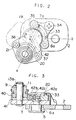
- a retractable wiper device of this kind is shown in Figs. 12 to 14.
- reference numeral 1 designates the output shaft of a reduction gear mechanism connected to a motor
- numeral 2 a first crank
- numeral 3 a second crank
- numeral 4 a first a nut for fastening the output shaft 1 and the first crank 2
- numeral 5 a projecting spindle projecting from the second crank 3
- numeral 6 a nut for supporting the second crank 3 on the first crank 2 in a rocking manner
- numerals 7 and 8 block edges formed on the first crank 2
- numeral 9 a spindle fixed in the second crank 3
- numeral 10 a cam fitted on the spindle 9
- numeral 11 a bearing member integrated with the cam
- numeral 12 a link
- numeral 13 a bearing member at the side of the link 12
- numeral 14 a wiper blade
- numeral 15 an arm for supporting the wiper blade 14
- numeral 16 a rocking shaft for the arm 15
- numeral 17
- the output shaft 1 of the motor is rotationally driven in a forward direction, as indicated by an arrow P in Fig. 14. If the first crank 2 is rotated in this direction, the second crank 3 associated through the link 12 and the rocking lever 17 with the wiper arm 15 is rotated on the pivot 5 in the direction opposite to the direction P relative to the first crank 2 by the rotational reaction until it is bent to abut against the block edge 8 of the first crank 2. Simultaneously with this, the stopper 18 is introduced into the recess 7a by the urging force of the spring 19 and engaged at the bent angle.
- the second crank 3 is rotated on the output shaft 1 in the direction of the arrow P while being bent with respect to the first crank 2, and the rocking shaft 16 is reciprocated by the link 12 and the rocking lever 17 so that the wiping operation is carried out by the wiper blade 14.
- the range for the wiper blade 14 to be reciprocated with the second crank 3 which is bent with respect to the first crank 2 is between a bottom turn position A and a top turn position C.
- a wiper switch (not shown) is turned off
- the motor is reversed by an automatic fixed-position stop mechanism (not shown) so that the wiper arm is moved from the aforementioned position, which is taken when the wiper switch (not shown) is turned off, and is stopped at the bottom turn position A of the aforementioned operation range.
- the first crank 2 is rotated in the direction opposite to that of the arrow P.
- the second crank 3 associated with the wiper blade 14 through the link 12 is rotated on the pivot 5 in the direction of the arrow P relative to the first crank 2 until it is rotated to abut against the block edge 7 of the first crank 2 and is extended.
- the stopper 18 is introduced into the recess 8a by the urging force of the spring 19 to engage with the same at the extended angle.
- crank effective length when the second crank 3 is extended linearly with respect to the first crank 2 i.e., the inter-axis length joining the output shaft 1 and the spindle 9 is larger than the inter-axis length joining the output shaft 1 and the spindle 9 when the second crank 3 is bent.
- the wiper blade 14 in the ordinary stop position i.e., the bottom turn position
- the wiper blade 14 in the ordinary stop position is retracted across the operation range into its retracted position B.
- the cam 10 fitted on the spindle 9 of the second crank 3 is rotated on the spindle 9 integrally with the link 12.
- the cam 10 pushes and suppresses the stopper 18 engaging the recess 7a and leaves, the stopper 18 when it rotates backward at a small angle (about 35 degrees) after the ordinary rotation (of 180 degrees).
- the cam 10 pushes and suppresses the stopper 18 engaging with the recess 8a.
- the retractable wiper device thus constructed is enabled by a simple mechanism to retract the wiper blade from the ordinary stop position A into the retracted position B.
- the cam 10 assumes a state in which it does not push the stopper 18, once its in its first rotation when the wiper device operates with the first crank 2 and the second crank 3 being bent at a desired angle.
- the binding force for inserting the stopper 18 into the recess 7a of the block edge 7 depends absolutely upon the pushing force of the spring 19 so that it is in an unstable state causing clattering or squeaking. Slight shocks are thereby caused at the leading end of the wiper blade 14 giving an unstable feel to the driver.
- Cam members 30 and 31 are arranged in place of the aforementioned cam 10 and are individually formed with two recesses 30a and 30b, and 31a and 31b at positions spaced at an angle ⁇ of 120 degrees, as shown from (A) to (C) in Fig. 15. Moreover, the cam member 30 to be fixed on the aforementioned bearing member 11 is formed with a concentric, arcuate groove 30c which extends from the surface and to the back and has a play angle of 60 degrees, for example. The other cam member 31 is equipped with a pin 31c to be fitted in that arcuate groove 30c.
- This proposal is intended to eliminate the drawback in the procedure for which the wiper blade 14 is operated from the retracted position B to ordinary rotation by the forward drive of the motor. Specifically, in the course of the relation between the first crank 2 and the second crank 3 to change from the linearly extended position to the bent position, the aforementioned stopper 18 comes out of the recess 8a toward the cam side. If, at this time, an external force such as an intense wind is exerted upon the wiper while the vehicle is running at a high speed, the wiper is forced upward in its rotating direction so that the cam member 30 relating to the link 12 and the rocking lever 17 is rotationally accelerated in the forward direction in addition to its ordinary rotations.
- the above-specified proposal forms a relief space 36 so that the stopper 18 may be inclined around the side of the first crank 2 in the forward direction of the second crank 3, as shown in Fig. 16.
- the spring 19 is arranged to keep the aforementioned stopper 18 in a predetermined position at all times.
- the aforementioned cam member 30 is rotationally accelerated in the forward direction, said stopper 18 is inclined into the relief space 36 against the elastic force of the spring 19. Then, the arcuate face at the outside of the cam comes into smooth contact with the trailing end face of the stopper 18 to prevent the cam member 30 and the stopper 18 from collision or hooking onto each other.
- cam members 30 and 31 disclosed in the aforementioned proposal are formed with the recesses 30a and 31a having different angular apertures, as shown in Fig. 17.
- One cam member 30 is formed with the concentric, arcuate groove 30b having a play angle of about 180 degrees, and the other cam member 31 is formed with the bulge 31b to be fitted in the arcuate groove 30b.
- Fig. 10 shows the operations where the blade is retracted from the top turn position C into the retracted position B by the backward drive of the motor.
- the wind screen is wet in the state shown at (A) in Fig. 10 and is dry or semi-dry in the state shown at (B) in Fig. 10.
- the crank arm With the wind screen being dry or semi-dry, as shown by broken lines in Fig. 11, the crank arm has its pitch changed from its bent state to its extended state, when in its retracting operation. As a result, the wiper blade has its speed dropped around the central portion of its wiping pattern so that the speed is increased to complete the retraction after the crank arm is extended. Thus, the operation feel is so bad as to raise an eyesore to the driver. Because of the aforementioned movements of the wiper blade, streaks of water droplets are left due to the change in the wiping speed of the blade, thus raising a problem of obstructing the field of vision of the driver.
- a first crank 2 is fixedly connected to a motor reduction output shaft 1 by means of a nut 4.
- a second crank 3 is rotatably connected to the first crank 2 through a sleeve 6a by means of a projecting pivot 5 which in turn is integrally fixed to the second crank 3.
- An arcuate block member 33 is fixed to the first crank 2 and is formed with engagement recesses 7a and 8a.
- a spindle 9 is fixed to the second crank 3.
- a cam is composed of first and second two-stacked cam members 40 and 41, as will be described hereinafter, and is rotatably fitted on the spindle 9.
- the upper first cam member 40 is formed integrally with a bearing member 11 which is fitted on the spindle 9.
- This bearing member 11 is connected to a link side bearing member 13 by a connecting pin 11a projecting from the surface thereof and is prevented from coming out by a snap ring 13b while being allowed to rotate on the spindle 9 integrally with a link 12.
- a wiper blade 14 is connected to one end of a wiper arm 15. The other end is fixed together with one end of a rocking lever 17 to a rocking shaft 16. The other end of the rocking lever 17 is fixedly connected to the link 12.
- the aforementioned arcuate block member 33 is fitted at its two ends 33a on two pins 32 anchored to the first crank 2 and is fixed at its generally central portion by a screw 34.
- the second crank 3 has its extension and bent angle regulated in such an angular position that the leading projection 3a of the second crank 3 abuts against the two ends 33a of the block member 33.
- This block member 33 is formed with the aforementioned recesses 7a and 8a for receiving a stopper 42 in the extended and bent angle positions.
- a guide frame 20 which is formed with a bulge facing the arcuate recess of the block member 33.
- the guide frame 20 is formed with a guide groove 35 for guiding the stopper 42 internally.
- This guide groove 35 is formed with a first relief space 36 which is expanded as a relief around the block member 33 in the forward direction of the second crank 3.
- the stopper 42 is always urged by a spring 19 in the reverse direction of the second crank 3 from the relief space 36.
- the first cam member 40 is formed integrally with the aforementioned bearing member 11, as shown in Fig. 5(B), and is positioned below the bearing member 11. This first cam member 40 is formed in its lower face with a concentric, arcuate groove 40c over an angular aperture of ⁇ 1. The cam member 40 is further formed in its lower face with a recess 40a having an angular aperture of ⁇ 3 at an angular position of ⁇ 2 with respect to the center line a bisecting the angular aperture of that arcuate groove 40c.
- the first cam member 40 is further formed in its lower face with a recess 40b which is cut at an angular position of ⁇ 4 over an angular aperture of ⁇ 5 at the opposite side of the recess 40a with respect to the center line a .
- the aforementioned second cam member 41 is formed with a projection 41c projecting from the side facing the first cam member 40, as shown in Fig. 6.
- the projection 41c thus formed is loosely fitted in the concentric, arcuate groove 40c of the first cam member 40.
- the second cam member 41 is further formed with recesses 41a and 41b having an angular aperture of ⁇ 7, which are positioned at an angle of ⁇ 6/2 at the righthand and lefthand sides of the projection 41c with respect to the center line.
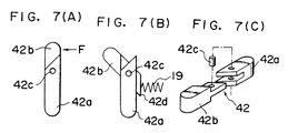
- the aforementioned stopper 42 is composed of a first stopper 42a and a second stopper 42b, as shown in Fig. 7. These two stoppers 42a and 42b are connected by a pin 42c which is inserted in their intermediate positions so as to rotate only in one direction.
- an external force F is exerted upon the second stopper 42b, as shown in (A) in Fig. 7, the second stopper 42b rotates on the pin 42c with respect to the first stopper 42a, as shown in (B) in Fig. 7.
- the rotating direction of this second stopper 42b is identical to the reverse direction of the first crank 2, as shown in Fig. 9.
- the guide frame 20 is formed with a second relief space 37. Since, the spring 19 for holding the stopper 42 in position is mounted between one end face 42d of the second stopper 42b and the guide frame 20, the first and second stoppers restore their original positions when the external force F is not applied.
- the aforementioned stopper 42 of the wiper device can also be suppressed in its abutment state at all times, no matter what angular position the cam might take, by associating the aforementioned two cam members 40 and 41 over the wiping actions of the second crank 3 in the forward rotation. Specifically, the bulge 41c of the second cam member 41 fitted in the concentric, arcuate groove 40c of the first cam member 40 moves relatively from the leading to the trailing ends of the arcuate groove 40c.
- the wiper switch When the wiper blade 14 is in the retracted position B, the wiper switch is turned OFF.
- the wiper motor has built therein an automatic fixed-position stopping mechanism (not shown) and a circuit (not shown) for a motor reversing mechanism. By the action of this circuit, the motor is continuously driven in the forward direction. However, the reverse rotation of the motor is not started before the wiper blade 14 has returned to the top turn position C.
- Fig. 1 shows at (A) and (B) the state in which the wiper blade 14 is returned to the top turn position C. From this state, the motor is rotated backward to rotate the output shaft 1 in the backward direction.
- Fig. 1 shows at (C) and (D) the state immediately after the reverse of the motor.
- the first cam member 40 is opened to have its pitch started to change with respect to the second cam member 41 until the recesses 40a and 41a of the two cam members 40 and 41 partially overlap in their positions facing the stopper 42. Since, however, the leading end of the stopper does not completely come out of the recess 7a, the bent states of the first and second cranks 2 and 3 are held so that the wiper blade 14 moves toward its bottom turn position A.
- the suppressed state of the stopper 42 by the first and second cam members 40 and 41 is released in the vicinity of the top reverse position C of the wiper blade 14.
- the first and second cranks 2 and 3 are promptly shifted from their bent states to their extended states immediately after the start of the reverse movement and cause the stopper 42 to move into the first relief space 36.
- the crank pitch is greatly changed by the inertia immediately after the turn of the wiper blade 14 even if the wind screen is wet.
- the large pitch change is retained by the frictional resistance.
- the shifts of the first and second cranks 2 and 3 to the extended states in the vicinity of the top turn position C is executed without fail irrespective of the state of the wind screen.
- Fig. 1 shows at (K) and (L) the state in which the wiper blade 14 reaches its retracted position B. Then, the automatic fixed-position stop mechanism operates to stop the backward drive of the motor. At this time, moreover, the first and second cam members 40 and 41 have their recesses 40b and 41b coinciding in their phases, and the suppressing action upon the stopper 42 is released at the time when the wiper blade 14 reaches its retracted position B.
- the operation of relieving the stopper 42 into the first relief space 36 against the urging force of the spring can be carried out not only upon the retraction of the wiper blade 14 (i.e., the backward rotation of the first crank 2) but also upon the wiping action by the wiper blade 14 (i.e, the forward rotation of the first crank 2).
- the following effects can be achieved by relieving the stopper 42 at the time of the forward rotation of the first crank 2.
- an external force such as an intense wind may be exerted upon the wiper blade 14, while the vehicle is running at a high speed, forcing the wiper blade 14 upward or in its rotating direction.
- the first cam member 40 associated With the link 12 and the rocking lever 17 is rotationally accelerated in the forward direction in addition to its ordinary rotation. If the stopper 42 is then inclined with respect to the first relief space 36, the first cam member 40 and the stopper 42 can be prevented from any collision or hooking onto to reduce the breakage of their parts.
- the recesses 40a and 41a of the first and second cam members 40 and 41 of the present embodiment have far narrower angular apertures than those of the recesses 30a and 31a of the cam members 30 and 31 in the prior art, as shown in Fig. 17.
- the wiper blade 14 With the wiper blade 14 being retracted, i.e., in the state immediately after the wiper blade 14 has been turned at the top turn position C, no surplus is left in the angular apertures of the recesses 30a and 31a of the first and second cam members 30 and 31, as shown in Fig. 18.
- the stopper and the cam in the prior art may possibly be locked or broken.
- the second stopper 42b is bent in the backward drive direction of the first crank 2 with respect to the first stopper 42a, as shown in Fig. 9, and is moved into the second relief space 37.
- the second stopper 42b is returned to its original state by the urging force of the spring 19.
- the positions for forming the individual recesses of the first and second cam members 40 and 41 can be changed into various modifications in addition to those of the embodiment.
- the cam shapes may be such that both the first and second cam members 40 and 41 are in the suppression releasing positions of the stopper 42 when the wiper blade 14 in the vicinity of the top turn position C while the first crank 2 is rotating backward.
- the cam for suppressing and releasing the stopper for holding the first and second cranks in the predetermined angular states is constructed of two cam members.
- these two cam members are associated to keep the stopper in the suppressed state at all times.
- the settings of the first and second cranks generally in the extended positions can be completed in the vicinity of the top turn position of the wiper blade irrespective of the state of the wind screen.
- the wiper blade In an intermediate position between the top and bottom turn positions, when the wiper blade is to be retracted, the wiper blade can be prevented from moving to have its wiping speed fluctuating.
Landscapes
- Engineering & Computer Science (AREA)
- Mechanical Engineering (AREA)
- Transmission Devices (AREA)
Claims (6)
- Zurückziehbare Scheibenwischeranordnung, mit:- einer ersten Kurbelplatte (2), die mit einer ersten Verriegelungsausnehmung (7a) und einer zweiten Verriegelungsausnehmung (8a) versehen ist, wobei die erste Kurbelplatte (2) mit einer Ausgangswelle (1) eines Übergangsstückes eines Wischermotors für die Drehung in einer Vorwärts- oder in einer Rückwärtsrichtung verbunden ist;- einer zweiten Kurbelplatte (3), die auf der ersten Kurbelplatte (2) mittels einer ersten Drehachse (5) drehbar angebracht ist, wobei die zweite Kurbelplatte (3) einen Führungsrahmen (20) hat, der daran zum gleitbaren Anbringen einer Arretierung (42) angebracht ist;- einer Entlastungseinrichtung (36), die innerhalb des Führungsrahmens (20) gebildet ist, um zu ermöglichen, daß die Arretierung (42) um ein Ende der Arretierung (42) benachbart einer der Ausnehmungen (7a, 8a) gekippt werden kann, wenn sich die erste Kurbelplatte (2) in die Vorwärts- bzw. Rückwärts-Richtung dreht;- einer Federeinrichtung (19) zum Zwingen der Arretierung (42) in ihre ursprüngliche Ruheposition in der umge kehrten Richtung der zweiten Kurbelplatte (3) von der Entlastungseinrichtung (36) zu allen Zeiten;- einer Verbindungseinrichtung (12, 17), die drehbar mit der zweiten Kurbelplatte (3) über eine zweite Drehwelle (9) zum Übertragen der Bewegung der zweiten Kurbelplatte (3) auf ein Wischerblatt (14) verbunden ist;- zwei überlagerten Nockenelementen (40, 41), die drehbar über der zweiten Drehwelle (9) angebracht sind, wobei jede von ihnen mit Kerben (40a, 40b, 41a, 41b) versehen ist und mit der Arretierung (42) in Eingriff bringbar ist, wobei eines (40) der Nockenelemente integral mit der Verbindungseinrichtung (12, 17) verbunden ist und das andere (41) der Nockenelemente so ausgelegt ist, daß es zusammen mit dem einen Nockenelement (40) mit einem begrenzten Leerlauf-Bereich bewegt werden kann, so daß die beiden Nockenelemente (40, 41) unter solchen Winkeln relativ zueinander gehalten werden, daß sie zusammenwirken, um die Arretierung (42) während der Drehung der ersten Kurbelplatte (2) in die Vorwärts-Richtung zu drücken und zu verriegeln und um die Arretierung (42) aus ihrem Eingriff in einer der Ausnehmungen (7a, 8a) freizusetzen, indem die Kerben (40a, 41a) in überlappender Beziehung miteinander sind, wenn die erste Kurbelplatte (2) sich in die Rückwärts-Richtung dreht,dadurch gekennzeichnet, daß
die Arretierung (42) einen ersten Arretierungsabschnitt (42a), der wahlweise in jede der Verriegelungsausnehmungen (7a, 8a) greifen kann, und einen zweiten Arretierungsabschnitt (42b), der gelenkig mit dem ersten Arretierungsabschnitt (42a) verbunden ist, aufweist und der zweite Arretierungsabschnitt (42b) schwenkbar in bezug auf den ersten Arretierungsabschnitt (42a) ist und eine Zwangskraft der Federeinrichtung (19) auf den Zweiten Arretierungsabschnitt (42b) wirkt, um so den zweiten Arretierungsabschnitt (42b) in einen früheren Zustand zu bringen, wenn der zweite Arretierungsabschnitt (42b) in eine Richtung entgegengesetzt zu der Richtung der Entlastungseinrichtung (36) verkippt und in einem Entlastungsraum (37) angeordnet ist, der in dem Führungsrahmen (20) vorgesehen ist, um so die Entlastungswirkung der Arretierung (42) von der einen Ausnehmung (7a, 8a) vor ihrem Eingriff in die andere Ausnehmung (8a, 7a) zu erhöhen. - Zurückziehbare Scheibenwischeranordnung nach Anspruch 1, bei dem ein vorbestimmter Winkel des Spiels zwischen dem ersten und zweiten Nockenelement durch eine Nut definiert ist, die entweder in dem ersten Nockenelement (40) oder dem zweiten Nockenelement (41) gebildet ist und von einer Mittenachse davon beabstandet und um sie gekrümmt ist, und einen Vorsprung, der in dem anderen der ersten und zweiten Nockenelemente (21) gebildet und in die Nut eingesetzt ist.
- Zurückziehbare Scheibenwischeranordnung nach Anspruch 1 oder 2, bei der eine zweite Fläche (40b) des ersten Nockenelementes (40) und eine vierte Fläche (41b) des zweiten Nockenelementes (41) mit Ausnehmungen zum Aufnehmen des Endabschnittes eines Stopperelementes (42) gebildet sind, das an den Seiten des ersten Nockenelementes (40) und des zweiten Nockenelementes (41) angeordnet ist.
- Zurückziehbare Scheibenwischeranordnung nach einem der vorangehenden Ansprüche, die weiterhin einen zweiten Entlastungsabschnitt zum Aufnehmen eines Endabschnittes des Stopperelementes (42), das gekrümmt ist, aufweist.
- Zurückziehbare Scheibenwischeranordnung nach einem der Ansprüche 2 bis 5, bei der die Federeinrichtung (19) eine Feder umfaßt, die so angeordnet ist, daß sie das Stopperelement (42) aus einem gekrümmten Zustand in einen nichtgekrümmten Zustand zurückführt.
- Zurückziehbare Scheibenwischeranordnung nach einem der vorangehenden Ansprüche, bei der der Eingriff des Stopperelementes (42) in die erste Kurbelplatte (2) durchgeführt wird, indem ein Ende des Stopperelementes (42) in eine Ausnehmung eingesetzt wird, die in einer ersten Kurbelplatte (2) gebildet ist.
Applications Claiming Priority (2)
| Application Number | Priority Date | Filing Date | Title |
|---|---|---|---|
| JP1168905A JPH0332963A (ja) | 1989-06-30 | 1989-06-30 | 格納式ワイパー装置 |
| JP168905/89 | 1989-06-30 |
Publications (3)
| Publication Number | Publication Date |
|---|---|
| EP0405535A2 EP0405535A2 (de) | 1991-01-02 |
| EP0405535A3 EP0405535A3 (en) | 1992-01-22 |
| EP0405535B1 true EP0405535B1 (de) | 1995-08-16 |
Family
ID=15876737
Family Applications (1)
| Application Number | Title | Priority Date | Filing Date |
|---|---|---|---|
| EP90112315A Expired - Lifetime EP0405535B1 (de) | 1989-06-30 | 1990-06-27 | Zurückziehbare Wischvorrichtung |
Country Status (4)
| Country | Link |
|---|---|
| US (1) | US5168594A (de) |
| EP (1) | EP0405535B1 (de) |
| JP (1) | JPH0332963A (de) |
| DE (1) | DE69021652T2 (de) |
Families Citing this family (2)
| Publication number | Priority date | Publication date | Assignee | Title |
|---|---|---|---|---|
| US5826294A (en) * | 1995-11-27 | 1998-10-27 | Ford Motor Company | Compact depressed park wiper system with clutch lock mechanism |
| DE19735818C2 (de) * | 1997-08-18 | 1999-10-21 | Daimler Chrysler Ag | Befestigungsvorrichtung für eine Scheibenwischeranlage eines Kraftfahrzeuges |
Family Cites Families (16)
| Publication number | Priority date | Publication date | Assignee | Title |
|---|---|---|---|---|
| US2753721A (en) * | 1953-10-05 | 1956-07-10 | Redmond Company Inc | Direction-sensitive linkage-lengthening arrangement, particularly for use in depressed parking of windshield wipers |
| GB978840A (en) * | 1962-10-09 | 1964-12-23 | Gen Motors Ltd | Windscreen wiper drive mechanisms |
| US3665772A (en) * | 1970-09-11 | 1972-05-30 | Ford Motor Co | Windshield wiper motor link depressed park mechanism |
| US3699605A (en) * | 1971-06-18 | 1972-10-24 | Gen Motors Corp | Depressed park windshield wiper |
| JPS57118957A (en) * | 1981-01-14 | 1982-07-24 | Nissan Motor Co Ltd | Wiper unit with rise-up mechanism |
| JPS57164843A (en) * | 1981-03-31 | 1982-10-09 | Nippon Denso Co Ltd | Driving device of window wiper |
| JPS59190648A (ja) * | 1983-04-13 | 1984-10-29 | Hitachi Ltd | 高温用基準電極 |
| GB2138674B (en) * | 1983-04-28 | 1986-06-25 | Rolls Royce Motors Ltd | A transmission mechanism |
| FR2581945B1 (fr) * | 1985-04-01 | 1987-08-07 | Marchal Equip Auto | Mecanisme de transmission, notamment pour essuie-glace, et dispositif d'essuie-glace equipe d'un tel mecanisme |
| JPS61244639A (ja) * | 1985-04-20 | 1986-10-30 | Asmo Co Ltd | 格納式ワイパ−装置 |
| FR2583491B1 (fr) * | 1985-06-12 | 1987-12-24 | Marchal Equip Auto | Mecanisme de transmission, en particulier pour essuie-glace, et dispositif d'essuie-glace equipe d'un tel mecanisme |
| JPS6345988A (ja) * | 1986-04-09 | 1988-02-26 | Hitachi Ltd | 輝度信号・色信号分離回路 |
| JPS62299452A (ja) * | 1986-06-18 | 1987-12-26 | Asmo Co Ltd | 格納式ワイパ−装置 |
| JPS62299453A (ja) * | 1986-06-18 | 1987-12-26 | Asmo Co Ltd | 格納式ワイパ−装置 |
| FR2630068B1 (fr) * | 1988-04-13 | 1990-08-24 | Valeo Systemes Dessuyage | Dispositif d'entrainement d'un balai d'essuie-glace permettant une mise en position de retrait |
| US4924726A (en) * | 1989-06-05 | 1990-05-15 | General Motors Corporation | Reverse to park mechanism with secure latching |
-
1989
- 1989-06-30 JP JP1168905A patent/JPH0332963A/ja active Pending
-
1990
- 1990-06-27 DE DE69021652T patent/DE69021652T2/de not_active Expired - Fee Related
- 1990-06-27 EP EP90112315A patent/EP0405535B1/de not_active Expired - Lifetime
- 1990-06-29 US US07/545,700 patent/US5168594A/en not_active Expired - Fee Related
Also Published As
| Publication number | Publication date |
|---|---|
| US5168594A (en) | 1992-12-08 |
| EP0405535A2 (de) | 1991-01-02 |
| EP0405535A3 (en) | 1992-01-22 |
| DE69021652D1 (de) | 1995-09-21 |
| JPH0332963A (ja) | 1991-02-13 |
| DE69021652T2 (de) | 1996-01-18 |
Similar Documents
| Publication | Publication Date | Title |
|---|---|---|
| GB2090729A (en) | Mechanism for controlling the parked position of a wiper blade assembly | |
| RU2274565C2 (ru) | Привод стеклоочистителя | |
| EP0200119B1 (de) | Zurückziehbare Wischeranordnung | |
| EP0706464B1 (de) | Mechanismus zum absenken des scheibenwischers in parkstellung | |
| US5075519A (en) | Windshield wiper switch | |
| JP2719608B2 (ja) | ワイパ | |
| EP0405535B1 (de) | Zurückziehbare Wischvorrichtung | |
| US4794818A (en) | Transmission mechanism, for windscreen wipers in particular, and a windscreen wiper device fitted with such a mechanism | |
| GB2138674A (en) | A transmission mechanism | |
| US4729144A (en) | Retractable type wiper apparatus | |
| EP0487859B1 (de) | Scheibenwischervorrichtung für Kraftfahrzeuge | |
| JP2836119B2 (ja) | ワイパ | |
| US5826294A (en) | Compact depressed park wiper system with clutch lock mechanism | |
| JP2836120B2 (ja) | ワイパ | |
| JPH07165021A (ja) | ワイパー装置 | |
| US2717518A (en) | Direction-sensitive linkage-lengthening arrangement, particularly for use in depresed parking of windshield wipers | |
| US4088035A (en) | Windshield wiper drive mechanism with depressed parking | |
| JPS62299452A (ja) | 格納式ワイパ−装置 | |
| KR910004262Y1 (ko) | 자동변속기의 파킹(Parking)장치 | |
| EP4339030A1 (de) | Fünf- und sechsstangen-verbindungsmechanismen für fahrzeugtreppen | |
| JP2587056B2 (ja) | 格納式ワイパ装置 | |
| US4729251A (en) | Stepping mechanism | |
| JPH05201313A (ja) | スクリーンワイパー装置 | |
| JPH0217957Y2 (de) | ||
| JPH0217959Y2 (de) |
Legal Events
| Date | Code | Title | Description |
|---|---|---|---|
| PUAI | Public reference made under article 153(3) epc to a published international application that has entered the european phase |
Free format text: ORIGINAL CODE: 0009012 |
|
| 17P | Request for examination filed |
Effective date: 19900627 |
|
| AK | Designated contracting states |
Kind code of ref document: A2 Designated state(s): DE IT |
|
| PUAL | Search report despatched |
Free format text: ORIGINAL CODE: 0009013 |
|
| AK | Designated contracting states |
Kind code of ref document: A3 Designated state(s): DE IT |
|
| 17Q | First examination report despatched |
Effective date: 19930429 |
|
| GRAA | (expected) grant |
Free format text: ORIGINAL CODE: 0009210 |
|
| ITF | It: translation for a ep patent filed | ||
| AK | Designated contracting states |
Kind code of ref document: B1 Designated state(s): DE IT |
|
| REF | Corresponds to: |
Ref document number: 69021652 Country of ref document: DE Date of ref document: 19950921 |
|
| PLBE | No opposition filed within time limit |
Free format text: ORIGINAL CODE: 0009261 |
|
| STAA | Information on the status of an ep patent application or granted ep patent |
Free format text: STATUS: NO OPPOSITION FILED WITHIN TIME LIMIT |
|
| 26N | No opposition filed | ||
| PGFP | Annual fee paid to national office [announced via postgrant information from national office to epo] |
Ref country code: DE Payment date: 20000502 Year of fee payment: 10 |
|
| PG25 | Lapsed in a contracting state [announced via postgrant information from national office to epo] |
Ref country code: DE Free format text: LAPSE BECAUSE OF NON-PAYMENT OF DUE FEES Effective date: 20010403 |
|
| PG25 | Lapsed in a contracting state [announced via postgrant information from national office to epo] |
Ref country code: IT Free format text: LAPSE BECAUSE OF NON-PAYMENT OF DUE FEES;WARNING: LAPSES OF ITALIAN PATENTS WITH EFFECTIVE DATE BEFORE 2007 MAY HAVE OCCURRED AT ANY TIME BEFORE 2007. THE CORRECT EFFECTIVE DATE MAY BE DIFFERENT FROM THE ONE RECORDED. Effective date: 20050627 |