EP0405176B1 - Taststift mit einem optischen Berührungssensor - Google Patents
Taststift mit einem optischen Berührungssensor Download PDFInfo
- Publication number
- EP0405176B1 EP0405176B1 EP90110413A EP90110413A EP0405176B1 EP 0405176 B1 EP0405176 B1 EP 0405176B1 EP 90110413 A EP90110413 A EP 90110413A EP 90110413 A EP90110413 A EP 90110413A EP 0405176 B1 EP0405176 B1 EP 0405176B1
- Authority
- EP
- European Patent Office
- Prior art keywords
- laser
- feeler pin
- resonator
- mirror
- pin according
- Prior art date
- Legal status (The legal status is an assumption and is not a legal conclusion. Google has not performed a legal analysis and makes no representation as to the accuracy of the status listed.)
- Expired - Lifetime
Links
Images

Classifications
-
- G—PHYSICS
- G01—MEASURING; TESTING
- G01B—MEASURING LENGTH, THICKNESS OR SIMILAR LINEAR DIMENSIONS; MEASURING ANGLES; MEASURING AREAS; MEASURING IRREGULARITIES OF SURFACES OR CONTOURS
- G01B11/00—Measuring arrangements characterised by the use of optical techniques
- G01B11/002—Measuring arrangements characterised by the use of optical techniques for measuring two or more coordinates
- G01B11/005—Measuring arrangements characterised by the use of optical techniques for measuring two or more coordinates coordinate measuring machines
- G01B11/007—Measuring arrangements characterised by the use of optical techniques for measuring two or more coordinates coordinate measuring machines feeler heads therefor
-
- Y—GENERAL TAGGING OF NEW TECHNOLOGICAL DEVELOPMENTS; GENERAL TAGGING OF CROSS-SECTIONAL TECHNOLOGIES SPANNING OVER SEVERAL SECTIONS OF THE IPC; TECHNICAL SUBJECTS COVERED BY FORMER USPC CROSS-REFERENCE ART COLLECTIONS [XRACs] AND DIGESTS
- Y10—TECHNICAL SUBJECTS COVERED BY FORMER USPC
- Y10S—TECHNICAL SUBJECTS COVERED BY FORMER USPC CROSS-REFERENCE ART COLLECTIONS [XRACs] AND DIGESTS
- Y10S33/00—Geometrical instruments
- Y10S33/04—Interferometer
-
- Y—GENERAL TAGGING OF NEW TECHNOLOGICAL DEVELOPMENTS; GENERAL TAGGING OF CROSS-SECTIONAL TECHNOLOGIES SPANNING OVER SEVERAL SECTIONS OF THE IPC; TECHNICAL SUBJECTS COVERED BY FORMER USPC CROSS-REFERENCE ART COLLECTIONS [XRACs] AND DIGESTS
- Y10—TECHNICAL SUBJECTS COVERED BY FORMER USPC
- Y10S—TECHNICAL SUBJECTS COVERED BY FORMER USPC CROSS-REFERENCE ART COLLECTIONS [XRACs] AND DIGESTS
- Y10S33/00—Geometrical instruments
- Y10S33/21—Geometrical instruments with laser
Definitions
- the luminous flux of the laser diode is detected by a photodiode.
- a control loop regulates the electrical operating current of the laser diode to stable or stable modulated light emission.
- a relative position measurement over several ⁇ m can be carried out with a linear signal. The effects of tilting the mirror are not described in either document.
- the entire structure should be simple, stable and reliable.
- the laser feedback interferometer is an integral part of the button.
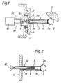
- Fig. 1 first shows a stylus 1, as it is used as a switching stylus in 3D measuring machines. It has a contact element 2 - typically a polished sapphire ball - a bar 3 and a base 4.
- a contact element 2 - typically a polished sapphire ball - a bar 3 and a base 4.
- a laser 8 is arranged in the base 4, the beam 3 is designed as a hollow tube and the area of the ball 2 lying in it is used as a mirror 2a.
- the wavelength of the laser diode 8 can also be modulated by current and / or temperature thereof.
- the tube used as the bar 3 can be very thin and light, since it only envelops the narrow laser beam 10 and preferably should not be rigid in order to bring about a detectable change in position of the mirror 2a with the smallest force between the contact element 2 and the object 5. For this purpose, it advantageously has a bending point 3a near the base 4.
- the inside of the pipe can be provided with a defined atmosphere or vacuum to avoid influences of dust, moisture, Exclude pressure and density fluctuations on the laser resonator.
- the contact element 2 can also be provided with a specially designed mirror 2b, which is optimized for the optical system.
- a plane mirror 2b with a special coating can be provided. The adjustment of laser diode 8 and plane mirror 2b is simplified, but the manufacturing effort for mirror 2b is increased.
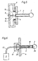
- the optical structure initially looks like an ordinary reflex light barrier. If the photodiodes 13a, 13b are part of an annular array, then, according to US Pat. No. 4,574,199, the axis of the tilt between mirror 2b and laser diode 8 can be seen from the position of the reflection on the photodiode array.
- the arrangement of the laser diode 8 with its end mirrors 8a and 8b and the mirror 2b is now carried out as a coupled laser resonator with three mirrors.
- the resonator quality and the operating conditions of the laser diode 8, such as current and temperature are selected in the basic position such that the threshold for the laser light emission is exceeded.
- a considerable light intensity is therefore incident on a photodiode 13a defined by the tilt direction of the mirror 2b.
- the arrangement thus acts as a threshold switch.
- this arrangement can work like that according to FIG. 1 and the change in the resonator quality can be detected by the electrical excitation current of the laser diode 8 or by an additional monitor photodiode. Because of the divergent light beam path to the photodiodes 13a, 13b, the hollow bar 3 must be wider than the embodiments in FIGS. 1 to 3.
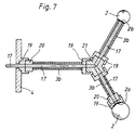
- an optical waveguide 17 is inserted into the beam path between the laser diode 8 and the third resonator mirror 2a on the contact element 2.
- optical waveguide 17 can be provided with a plug 19 and socket 20 of a commercially available type. Then the whole stylus can be easily replaced.
- the optical waveguide 17 can also fill the entire length between the laser 8 and the third resonator mirror 2a, 2b, that is to say, for example, replace the cavity in the beam 3 in FIG. 1 and thus reduce light losses. Then in many cases lens elements 16, 18 can be dispensed with, especially if gradient index fibers are used as optical waveguide 17. If the probe element 2 touches an object 5, the optical waveguide 17 is bent or compressed in this case. In versions of the optical waveguide 17, which are based on changes in the optical properties, for. B. the damping, or the polarization properties react, these changes reinforce the change in quality of the resonator when probing.
Landscapes
- Physics & Mathematics (AREA)
- General Physics & Mathematics (AREA)
- Length Measuring Devices By Optical Means (AREA)
- Length Measuring Devices With Unspecified Measuring Means (AREA)
- Instruments For Measurement Of Length By Optical Means (AREA)
Applications Claiming Priority (2)
| Application Number | Priority Date | Filing Date | Title |
|---|---|---|---|
| DE3920716A DE3920716C1 (enExample) | 1989-06-24 | 1989-06-24 | |
| DE3920716 | 1989-06-24 |
Publications (2)
| Publication Number | Publication Date |
|---|---|
| EP0405176A1 EP0405176A1 (de) | 1991-01-02 |
| EP0405176B1 true EP0405176B1 (de) | 1992-10-28 |
Family
ID=6383480
Family Applications (1)
| Application Number | Title | Priority Date | Filing Date |
|---|---|---|---|
| EP90110413A Expired - Lifetime EP0405176B1 (de) | 1989-06-24 | 1990-06-01 | Taststift mit einem optischen Berührungssensor |
Country Status (4)
| Country | Link |
|---|---|
| US (1) | US5103572A (enExample) |
| EP (1) | EP0405176B1 (enExample) |
| JP (1) | JPH0342505A (enExample) |
| DE (2) | DE3920716C1 (enExample) |
Families Citing this family (29)
| Publication number | Priority date | Publication date | Assignee | Title |
|---|---|---|---|---|
| DE4204632A1 (de) * | 1990-08-28 | 1993-08-19 | Leitz Messtechnik | Zentriereinrichtung fuer einen mechanischen tastkopf |
| GB9116044D0 (en) * | 1991-07-24 | 1991-09-11 | Nat Res Dev | Probes |
| US5394757A (en) * | 1992-06-25 | 1995-03-07 | Thiokol Corporation | Multiple stylus probe attachment and methods |
| DE4238724C1 (de) * | 1992-11-17 | 1993-12-23 | Leitz Mestechnik Gmbh | Zentriereinrichtung für einen mechanischen Taster |
| DE4244240B4 (de) * | 1992-12-24 | 2005-07-07 | Carl Zeiss Industrielle Messtechnik Gmbh | Taststift |
| DE4325744C1 (de) * | 1993-07-31 | 1994-12-15 | Heidenhain Gmbh Dr Johannes | Mehrkoordinaten-Tastkopf |
| US5619318A (en) * | 1993-08-10 | 1997-04-08 | Olympus Optical Co., Ltd. | Optical displacement sensor |
| EP0988505B1 (de) * | 1997-06-12 | 2002-01-09 | Werth Messtechnik GmbH | Koordinatenmessgerät mit biegeelastischer Tasterverlängerung und optischem Sensor |
| US5883875A (en) * | 1997-09-02 | 1999-03-16 | International Business Machines Corporation | Short coherent-length optical tomograph for high density volume optical data storage devices |
| US5948960A (en) * | 1998-02-09 | 1999-09-07 | Intel Corporation | HTMU test handler throw measuring unit |
| GB9907644D0 (en) * | 1999-04-06 | 1999-05-26 | Renishaw Plc | Surface sensing device with optical sensor |
| WO2002025206A1 (de) * | 2000-09-20 | 2002-03-28 | Werth Messtechnik Gmbh | Anordnung und verfahren zum opto-taktilen messen von strukturen |
| US6978551B2 (en) | 2000-12-22 | 2005-12-27 | Krake Kelly R | Picture hanging device |
| DE10108774A1 (de) * | 2001-02-23 | 2002-09-05 | Zeiss Carl | Koordinatenmessgerät zum Antasten eines Werkstücks, Tastkopf für ein Koordinatenmessgerät und Verfahren zum Betrieb eines Koordinatenmessgerätes |
| GB0114360D0 (en) * | 2001-06-13 | 2001-08-08 | Renishaw Plc | Stylus orientation |
| DE10153606A1 (de) * | 2001-11-02 | 2003-05-15 | Univ Hannover | Vorrichtung zur Bestimmung einer Bauteilauslenkung |
| US20040068881A1 (en) * | 2002-10-15 | 2004-04-15 | Optical Gaging Products, Inc. | Viscous coupled micro interposer |
| KR20050063790A (ko) * | 2002-10-29 | 2005-06-28 | 코닌클리케 필립스 일렉트로닉스 엔.브이. | 좌표 측정 디바이스와 물체의 위치 측정 방법 |
| GB0506158D0 (en) * | 2005-03-24 | 2005-05-04 | Renishaw Plc | Measurement probe |
| JP4783575B2 (ja) * | 2005-03-24 | 2011-09-28 | シチズンホールディングス株式会社 | 接触式変位測長器 |
| GB0508388D0 (en) | 2005-04-26 | 2005-06-01 | Renishaw Plc | Surface sensing device with optical sensor |
| DE102005037160B4 (de) * | 2005-08-06 | 2007-09-06 | SIOS Meßtechnik GmbH | Verfahren und Vorrichtung zur taktilen Erfassung |
| JP4933775B2 (ja) | 2005-12-02 | 2012-05-16 | 独立行政法人理化学研究所 | 微小表面形状測定プローブ |
| US20070204473A1 (en) * | 2006-03-03 | 2007-09-06 | Honda Motor Co., Ltd. | Spindle locating laser for nut runner |
| EP2385339A1 (en) | 2010-05-05 | 2011-11-09 | Leica Geosystems AG | Surface sensing device with optical monitoring system |
| DE102012003223A1 (de) * | 2012-02-20 | 2013-08-22 | Carl Zeiss 3D Automation Gmbh | Kugel-Schaft-Verbindung |
| EP2657642A1 (de) * | 2012-04-24 | 2013-10-30 | Hexagon Technology Center GmbH | Sensorelement für eine Messmaschine, insbesondere eine Koordinatenmessmaschine |
| DE102015119274B4 (de) * | 2015-11-09 | 2018-07-12 | Björn Habrich | Verfahren und Vorrichtung zur Bestimmung der räumlichen Position eines Gegenstandes mittels interferometrischer Längenmessung |
| US9835433B1 (en) | 2017-05-09 | 2017-12-05 | Tesa Sa | Touch trigger probe |
Family Cites Families (20)
| Publication number | Priority date | Publication date | Assignee | Title |
|---|---|---|---|---|
| US2846919A (en) * | 1954-04-27 | 1958-08-12 | Penn Optical And Instr Co | Interferometer |
| US4153370A (en) * | 1977-12-05 | 1979-05-08 | The United States Of America As Represented By The United States Department Of Energy | Microinterferometer transducer |
| DE2937431C2 (de) * | 1979-09-15 | 1987-02-05 | Ernst Leitz Wetzlar Gmbh, 6330 Wetzlar | Einrichtung zur Meßwerterfassung an Prüflingen |
| US4475812A (en) * | 1980-04-08 | 1984-10-09 | The United States Of America As Represented By The Secretary Of The Navy | Cavity coupled optical condition sensor |
| NL8005259A (nl) * | 1980-09-22 | 1982-04-16 | Philips Nv | Inrichting voor het meten aan het oppervlak van een voorwerp. |
| US4453082A (en) * | 1980-11-14 | 1984-06-05 | Diffracto Ltd. | Coordinate measuring method and device |
| US4694184A (en) * | 1980-11-14 | 1987-09-15 | Diffracto Ltd. | Coordinate measuring method and device using a contact member |
| SU993011A1 (ru) * | 1981-06-24 | 1983-01-30 | Московский Ордена Ленина Институт Инженеров Геодезии, Аэрофотосъемки И Картографии | Интерферометр дл измерени больших перемещений |
| US4574199A (en) * | 1983-01-27 | 1986-03-04 | Diffracto Ltd. | Sensing location of an object |
| US4643577A (en) * | 1983-07-15 | 1987-02-17 | Wero Ohg Roth & Co. | Length measuring apparatus based on the dual laser beam interferometer principle |
| US4513507A (en) * | 1983-09-02 | 1985-04-30 | Bendix Automation Company | Contact sensing probe for a measuring apparatus |
| JPH0697261B2 (ja) * | 1984-06-01 | 1994-11-30 | シャープ株式会社 | 半導体レ−ザを用いた微小変位測定装置 |
| JPS617402A (ja) * | 1984-06-21 | 1986-01-14 | Sotsukishiya:Kk | 位置検出装置 |
| JPH0690009B2 (ja) * | 1985-02-28 | 1994-11-14 | シャープ株式会社 | 半導体レーザを用いた微小変位測定方法 |
| SU1413421A1 (ru) * | 1985-10-14 | 1988-07-30 | Предприятие П/Я А-1758 | Измерительна головка |
| SU1394034A1 (ru) * | 1985-10-14 | 1988-05-07 | Предприятие П/Я А-1758 | Измерительна головка |
| US4824240A (en) * | 1986-04-15 | 1989-04-25 | Hughes Aircraft Company | Internal laser interferometer |
| DD252233A1 (de) * | 1986-09-01 | 1987-12-09 | Zeiss Jena Veb Carl | Tasteranordnung mit fotoelektrischer signalgewinnung |
| US4714346A (en) * | 1986-09-22 | 1987-12-22 | Gte Laboratories Incorporated | Frequency chirped interferometric displacement sensors and mechanical translation tips therefor |
| DE3824549A1 (de) * | 1988-07-20 | 1990-01-25 | Zeiss Carl Fa | Lagerung fuer tastkoepfe |
-
1989
- 1989-06-24 DE DE3920716A patent/DE3920716C1/de not_active Expired - Fee Related
-
1990
- 1990-06-01 DE DE9090110413T patent/DE59000402D1/de not_active Expired - Fee Related
- 1990-06-01 EP EP90110413A patent/EP0405176B1/de not_active Expired - Lifetime
- 1990-06-22 JP JP2165487A patent/JPH0342505A/ja active Pending
- 1990-06-25 US US07/542,833 patent/US5103572A/en not_active Expired - Lifetime
Also Published As
| Publication number | Publication date |
|---|---|
| EP0405176A1 (de) | 1991-01-02 |
| JPH0342505A (ja) | 1991-02-22 |
| DE3920716C1 (enExample) | 1990-11-29 |
| DE59000402D1 (de) | 1992-12-03 |
| US5103572A (en) | 1992-04-14 |
Similar Documents
| Publication | Publication Date | Title |
|---|---|---|
| EP0405176B1 (de) | Taststift mit einem optischen Berührungssensor | |
| DE68929262T2 (de) | Konfokales Mikroskop | |
| DE69001386T2 (de) | Hochempfindliches Positionsmess-Verfahren. | |
| EP0242436B1 (de) | Vorrichtung zur Messung kleiner Längen | |
| DE69115914T2 (de) | Interferenzmikroskop | |
| DE3783101T2 (de) | Anordnung zum nachweis des brennpunktes. | |
| DE69320992T2 (de) | Optisches nahfeldmikroskop | |
| EP0438675A2 (de) | Interferometrischer Sensor zur Messung von Abstandsänderungen einer kleinen Fläche | |
| DE3817337A1 (de) | System zur messung von oberflaechenprofilen | |
| DE10106699C2 (de) | Berührungssensor und Vorrichtung zum Schutz eines hervorstehenden Bauteils | |
| DE69232905T2 (de) | Elektrooptische Messanordnung zum Messen eines elektrischen Signals in einem elektronischen Bauteil | |
| DE3124357C2 (de) | Längenmeßeinrichtung | |
| AT392537B (de) | Interferometeranordnung, insbesondere zur entfernungs- bzw. verschiebewegbestimmung eines beweglichen bauteiles | |
| DE10125885B4 (de) | Sensorvorrichtung zur schnellen optischen Abstandsmessung nach dem konfokalen optischen Abbildungsprinzip | |
| DE112020000803B4 (de) | Verfahren und Vorrichtung zur Charakterisierung von Laserverstärkerchips | |
| EP1176407B1 (de) | Vorrichtung und Verfahren zur Infrarot-Temperaturmessung | |
| DE60211388T2 (de) | Sensor mit kantilever und optischem resonator | |
| EP1714109B1 (de) | Konfokaler abstandssensor | |
| EP0401694A1 (de) | Interferometeranordnung | |
| DE69115477T2 (de) | Interferometrisches system und verfahren | |
| DE4401972C2 (de) | Einrichtung zur optischen Abtastung einer Fläche | |
| DE112022001553T5 (de) | Vorrichtung und verfahren zur erfassung von bewegungen entlang einer achse | |
| KR100343813B1 (ko) | 광섬유나 광도파로 표면의 굴절률구조 측정장치 및 방법 | |
| DE19962078B4 (de) | Verfahren und Vorrichtung zur interferentiellen Abstandsmessung | |
| EP0146701A1 (de) | Anordnung zur Abstandsdetektion zwischen einem Objekt und einem Ultraschall-Objektiv |
Legal Events
| Date | Code | Title | Description |
|---|---|---|---|
| PUAI | Public reference made under article 153(3) epc to a published international application that has entered the european phase |
Free format text: ORIGINAL CODE: 0009012 |
|
| AK | Designated contracting states |
Kind code of ref document: A1 Designated state(s): CH DE FR GB IT LI SE |
|
| RAP1 | Party data changed (applicant data changed or rights of an application transferred) |
Owner name: LEICA INDUSTRIEVERWALTUNG GMBH |
|
| 17P | Request for examination filed |
Effective date: 19910513 |
|
| 17Q | First examination report despatched |
Effective date: 19920409 |
|
| GRAA | (expected) grant |
Free format text: ORIGINAL CODE: 0009210 |
|
| AK | Designated contracting states |
Kind code of ref document: B1 Designated state(s): CH DE FR GB IT LI SE |
|
| GBT | Gb: translation of ep patent filed (gb section 77(6)(a)/1977) | ||
| REF | Corresponds to: |
Ref document number: 59000402 Country of ref document: DE Date of ref document: 19921203 |
|
| ITF | It: translation for a ep patent filed | ||
| ET | Fr: translation filed | ||
| PLBE | No opposition filed within time limit |
Free format text: ORIGINAL CODE: 0009261 |
|
| STAA | Information on the status of an ep patent application or granted ep patent |
Free format text: STATUS: NO OPPOSITION FILED WITHIN TIME LIMIT |
|
| 26N | No opposition filed | ||
| REG | Reference to a national code |
Ref country code: FR Ref legal event code: TP |
|
| EAL | Se: european patent in force in sweden |
Ref document number: 90110413.3 |
|
| PGFP | Annual fee paid to national office [announced via postgrant information from national office to epo] |
Ref country code: GB Payment date: 19960516 Year of fee payment: 7 |
|
| PGFP | Annual fee paid to national office [announced via postgrant information from national office to epo] |
Ref country code: FR Payment date: 19960521 Year of fee payment: 7 |
|
| PGFP | Annual fee paid to national office [announced via postgrant information from national office to epo] |
Ref country code: SE Payment date: 19960523 Year of fee payment: 7 |
|
| PGFP | Annual fee paid to national office [announced via postgrant information from national office to epo] |
Ref country code: CH Payment date: 19960524 Year of fee payment: 7 |
|
| PG25 | Lapsed in a contracting state [announced via postgrant information from national office to epo] |
Ref country code: GB Effective date: 19970601 |
|
| PG25 | Lapsed in a contracting state [announced via postgrant information from national office to epo] |
Ref country code: SE Effective date: 19970602 |
|
| PG25 | Lapsed in a contracting state [announced via postgrant information from national office to epo] |
Ref country code: LI Free format text: LAPSE BECAUSE OF NON-PAYMENT OF DUE FEES Effective date: 19970630 Ref country code: CH Free format text: LAPSE BECAUSE OF NON-PAYMENT OF DUE FEES Effective date: 19970630 |
|
| GBPC | Gb: european patent ceased through non-payment of renewal fee |
Effective date: 19970601 |
|
| REG | Reference to a national code |
Ref country code: CH Ref legal event code: PL |
|
| PG25 | Lapsed in a contracting state [announced via postgrant information from national office to epo] |
Ref country code: FR Free format text: LAPSE BECAUSE OF NON-PAYMENT OF DUE FEES Effective date: 19980227 |
|
| EUG | Se: european patent has lapsed |
Ref document number: 90110413.3 |
|
| REG | Reference to a national code |
Ref country code: FR Ref legal event code: ST |
|
| REG | Reference to a national code |
Ref country code: FR Ref legal event code: ST |
|
| PG25 | Lapsed in a contracting state [announced via postgrant information from national office to epo] |
Ref country code: IT Free format text: LAPSE BECAUSE OF NON-PAYMENT OF DUE FEES;WARNING: LAPSES OF ITALIAN PATENTS WITH EFFECTIVE DATE BEFORE 2007 MAY HAVE OCCURRED AT ANY TIME BEFORE 2007. THE CORRECT EFFECTIVE DATE MAY BE DIFFERENT FROM THE ONE RECORDED. Effective date: 20050601 |
|
| PGFP | Annual fee paid to national office [announced via postgrant information from national office to epo] |
Ref country code: DE Payment date: 20080620 Year of fee payment: 19 |
|
| PG25 | Lapsed in a contracting state [announced via postgrant information from national office to epo] |
Ref country code: DE Free format text: LAPSE BECAUSE OF NON-PAYMENT OF DUE FEES Effective date: 20100101 |