EP0403750A2 - Rotor mit einem schlaggelenkigen Blattanschluss im Rotorzentrum - Google Patents
Rotor mit einem schlaggelenkigen Blattanschluss im Rotorzentrum Download PDFInfo
- Publication number
- EP0403750A2 EP0403750A2 EP90107050A EP90107050A EP0403750A2 EP 0403750 A2 EP0403750 A2 EP 0403750A2 EP 90107050 A EP90107050 A EP 90107050A EP 90107050 A EP90107050 A EP 90107050A EP 0403750 A2 EP0403750 A2 EP 0403750A2
- Authority
- EP
- European Patent Office
- Prior art keywords
- rotor
- drive
- drive shaft
- ring
- rotor hub
- Prior art date
- Legal status (The legal status is an assumption and is not a legal conclusion. Google has not performed a legal analysis and makes no representation as to the accuracy of the status listed.)
- Granted
Links
Images
Classifications
-
- B—PERFORMING OPERATIONS; TRANSPORTING
- B64—AIRCRAFT; AVIATION; COSMONAUTICS
- B64C—AEROPLANES; HELICOPTERS
- B64C27/00—Rotorcraft; Rotors peculiar thereto
- B64C27/32—Rotors
- B64C27/37—Rotors having articulated joints
- B64C27/41—Rotors having articulated joints with flapping hinge or universal joint, common to the blades
Definitions
- the invention relates to a rotor according to the preamble of patent claim 1.
- the invention is therefore based on the object of achieving the same synchronism with its drive shaft in a rotor of the type mentioned at the outset by means which at the same time are able to perform the aforementioned function of an effective force connection in the direction of the blade from the rotor hub to the drive shaft.
- the design characterized in claim 2 ensures a uniform stress distribution over the ring disk radius.
- the embodiment characterized in claim 4 not only enables the use of simple, releasable connecting means, but also ensures the spacing of the ring disks from the driving disk and rotor hub, which is necessary to fulfill the function of the spring ring.
- the invention with the design of the spring ring characterized in sub-claim 3 is particularly suitable for its formation from fiber-reinforced plastic with relatively little manufacturing effort and thus also contributes to the effort to reduce the rotor weight.
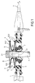
- the rotors shown, for example for a tilt rotor aircraft are those of the so-called semi-rigid construction with an articulated blade connection of all rotor blades 1 in the rotor center by means of a spherical bearing 2 which can be moved on all sides, preferably in the form of an elastomer bearing which is fixedly arranged on a rotor drive shaft 3.
- this (striking) joint bearing 2 is the basis of a rigid rotor hub 4 that unites the rotor blades 1.
- the arrangement of the joint bearing 2 with the (striking) joint means shown in FIG.
- the latter is with the drive disk 5 via one radial distance coupled around the drive shaft 3 (and expediently also coaxially) arranged spring ring 6.
- the spring ring 6 is not only intended to ensure the transmission of torque to the rotor hub 4 without impairing the blade stroke movements by means of the spherical bearing 2, but also to perform the function of a so-called impact spring, i.e.
- the spring ring 6 is split by an all-round symmetrical profile recess 6.1 into two ring disks 6.2, one of which is assigned to the rotor hub 4 and one driving disk 5.
- the connection 7 of the individual annular disk 6 with the rotor hub 4 or driving disk 5 is limited to the outer edge of the disk, for which purpose the annular disks 6.2 each have a material thickening 6.3 on the relevant edge surface.
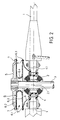
- the V-shaped profile cross section selected according to FIG. 1 for the spring washer 6 is of course also advantageous, in contrast to the arrangement of the spherical bearing 2 in the rotor plane 4.1 preferred according to FIG. 2, the profile of the drive plate 5 shown offset from the spring washer 6 and a spacer ring 8 interposed between the rotor hub 4 and the spring ring 6.
- the U-shaped profile cross section preferred for the spring ring 6 in the arrangement according to FIG. 2 has the same as that V-shaped profile cross-section according to FIG.
- the spring washer 6 can be produced from fiber-reinforced plastic with relatively little manufacturing effort, and without problems with the tapered shape of the washers 6.2 shown from the common spring washer root 6.4. This also ensures a uniform distribution of stress over the ring disk radius under impact bending stress of the ring disks 6.2.
Landscapes
- Engineering & Computer Science (AREA)
- Mechanical Engineering (AREA)
- Aviation & Aerospace Engineering (AREA)
- Structures Of Non-Positive Displacement Pumps (AREA)
- Turbine Rotor Nozzle Sealing (AREA)
Abstract
Description
- Die Erfindung betrifft einen Rotor gemäß dem Oberbegriff des Patentanspruchs 1.
- Bei einem derartigen sog. halbstarren Rotor beispielsweise gemäß der US-PS 47 08 591 erfolgt zur Entlastung des Blattanschlußgelenkes von den Antriebsmomenten der Rotorantrieb mittels der Antriebswelle über zwei flexible Faltenbälge in symmetrischer Anordnung (oberhalb bzw. unterhalb) zu einer um das Blattanschlußgelenk positionierten ringscheibenförmigen Rotornabe, wobei der Antriebswelle je Faltenbalg eine Mitnehmerscheibe zugeordnet ist. Durch solche Faltenbälge läßt sich beim Blattschlagen eine gleichförmige Drehmitnahme des Rotors, d.h. Gleichlauf desselben mit der Antriebswelle sicherstellen, sofern es unter Torsionslast nicht zu einem Ausknicken der Balgwandung kommen kann. Jedoch sind diese Faltenbälge, als Hüllwand des Blattanschlußgelenkes, so großflächig zu dimensionieren, daß sie nicht zu einer Kraftverbindung von der Rotornabe zur Antriebswelle nutzbar sind, über welche in Blattschlagrichtung an der Antriebswelle Steuermomente zur Lagesteuerung des Drehflügelflugzeugs bewirkbar sind.
- Der Erfindung liegt daher die Aufgabe zugrunde, bei einem Rotor der eingangs genannten Art Gleichlauf desselben mit seiner Antriebswelle durch Mittel zu erreichen, welche zugleich die vorgenannte Funktion einer in Blattschlagrichtung wirksamen Kraftverbindung von der Rotornabe zur Antriebswelle zu erfüllen vermögen.
- Diese Aufgabe ist für einen gattungsgemäßen Rotor mit den kennzeichnenden Merkmalen des Patentanspruchs 1 gelöst. Hiernach erfolgt die Kupplung der Rotornabe mit der Antriebswelle durch einen diese aufgrund seiner Gestaltung sowohl in Rotordrehrichtung als auch in Blattschlagrichtung kraftschlüssig verbindenden Federring, wobei dieser Winkelbeschleunigungen zwischen der Antriebswelle und dem angetriebenen Rotor unterbindet, dabei aber, je nach Wahl der Federkennung, dessen Schlagwinkelbeweglichkeit sicherstellt und zugleich als Element von belastungsabhängiger Starrheit in Blattschlagrichtung, die Funktion einer sog. Schlagfeder erfüllt, mittels welcher durch an der Rotornabe einwirkende Steuerkräfte (einer Lagesteuerung) entsprechende Steuermomente an der Antriebswelle (in Blattschlagrichtung) bewirkbar sind. Bei dieser Belastung des Federringes (auf Blattschlagbiegung) läßt sich durch die im Anspruch 2 gekennzeichnete Gestaltung eine gleichmäßige Spannungsverteilung über den Ringscheibenradius sicherstellen. Die im Anspruch 4 gekennzeichnete Ausgestaltung ermöglicht hierbei nicht nur die Benutzung einfacher, lösbarer Verbindungsmittel, sondern gewährleistet auch die zur Funktionserfüllung des Federringes erforderliche Distanzierung der Ringscheiben von der Mitnehmerscheibe und Rotornabe.
- Schließlich ist die Erfindung mit der im Unteranspruch 3 gekennzeichneten Ausgestaltung des Federringes für dessen Ausbildung aus faserverstärktem Kunststoff mit relativ geringem Fertigungsaufwand besonders geeignet und erfüllt somit auch einen Beitrag im Bestreben nach einer Reduzierung des Rotorgewichts.
- Im folgenden wird die Erfindung anhand zweier Ausführungsbeispiele weiter erläutert. Dabei zeigt die Zeichnung in je einer Seitenansicht das Zentrum zweier halbstarrer Rotoren, und zwar in
- Fig. 1 mit einem oberhalb der Rotordrehebene wirkenden zentralen Blattschlaggelenk und
- Fig. 2 mit einem in der Rotordrehebene angeordneten zentralen Blattschlaggelenk.
- Die dargestellten Rotoren, z.B. für ein Kipprotorflugzeug, sind solche der sog. halbstarren Bauweise mit einem schlaggelenkigen Blattanschluß sämtlicher Rotorblätter 1 im Rotorzentrum mittels eines allseitig winkelbeweglichen Gelenklagers 2 vorzugsweise in Form eines Elastomerlagers, welches auf einer Rotor-Antriebswelle 3 festsitzend angeordnet ist. Andererseits ist dieses (Schlag-)Gelenklager 2 die Basis einer die Rotorblätter 1 vereinigenden biegesteifen Rotornabe 4. Die in Fig. 1 dargestellte Anordnung des Gelenklagers 2 mit dem (Schlag-)Gelenkmittel punkt 2.1 oberhalb der Rotordrehebene 4.1 (sog. "underslung") hat gegenüber der Anordnung gemäß Fig. 2 den Vorteil einer zusätzlichen Stabilisierung des Rotors beim Anlassen (Anlaufen) und Abbremsen. Die Gegenüberstellung der Fig. 1 und 2 verdeutlicht, daß die nachfolgend erläuterte Erfindung auf eine bestimmte Positionierung und Ausbildung des Gelenklagers 2 nicht beschränkt und einzige Voraussetzung ein Rotorantrieb über eine steife Mitnehmerscheibe 5 zwischen der Antriebswelle 3 und Rotornabe 4 ist. Um mittels dieser Mitnehmerscheibe 5 ein Drehen der Rotornabe 4 und damit einen Umlauf der Rotorblätter 1 so zu bewirken, daß Winkelbeschleunigungen (bzw. -verzögerungen) zwischen der Antriebswelle 3 und Rotornabe 4 beim Blattschlagen ausgeschlossen sind, ist letztere mit der Mitnehmerscheibe 5 über einen mit radialem Abstand um die Antriebswelle 3 (und hierzu zweckmäßig auch koaxial) angeordneten Federring 6 gekuppelt. Der Federring 6 soll nicht nur die Drehmomentenübertragung auf die Rotornabe 4 sicherstellen, ohne die Blattschlagbewegungen mittels des Gelenklagers 2 zu beeinträchtigen, sondern dabei auch die Funktion einer sog. Schlagfeder erfüllen, d.h. soll zugleich an der Rotornabe 4 in Blattschlagrichtung einwirkende Steuerkräfte einer Lagesteuerung des betreffenden Drehflügelflugzeugs auf die Antriebswelle 3 übertragen. Um diese Doppelfunktion erfüllen zu können, ist der Federring 6 durch eine ringsum symmetrische Profilvertiefung 6.1 in zwei Ringscheiben 6.2 gespalten, von denen je eine der Rotornabe 4 und Mitnehmerscheibe 5 zugeordnet ist. Hierbei ist die Verbindung 7 der einzelnen Ringscheibe 6 mit der Rotornabe 4 bzw. Mitnehmerscheibe 5 (z.B. mittels Schrauben) auf den Scheibenaußenrand beschränkt, wozu die Ringscheiben 6.2 an der betreffenden Randfläche jeweils eine Materialaufdickung 6.3 aufweisen. Damit ist die zur Funktionserfüllung erforderliche Bewegungsfreiheit der Ringscheiben 6.2 gegenüber der Rotornabe 4 bzw. Mitnehmerscheibe 5 sichergestellt. In diesem Sinne von Vorteil ist selbstverständlich auch der gemäß Fig. 1 für den Federring 6 gewählte V-förmige Profilquerschnitt, dagegen bei der gemäß Fig. 2 bevorzugten Anordnung des Gelenklagers 2 in der Rotordrehebene 4.1 das dargestellte vom Federring 6 abgesetzte Profil der Mitnehmerscheibe 5 sowie ein der Rotornabe 4 und dem Federring 6 zwischengefügter Distanzscheibenring 8. Der bei der Anordnung gemäß Fig. 2 für den Federring 6 bevorzugte U-förmige Profilquerschnitt hat wie der V-förmige Profilquerschnitt gemäß Fig. 2 den schon erwähnten Vorteil, daß der Federring 6 mit relativ geringem Fertigungsaufwand aus faserverstärktem Kunststoff herstellbar ist, und zwar problemlos mit der dargestellten verjüngten Form der Ringscheiben 6.2 von der gemeinsamen Federringwurzel 6.4 aus. Damit ist auch eine gleichmäßige Spannungsverteilung über den Ringscheibenradius unter Schlagbiegebelastung der Ringscheiben 6.2 gewährleistet.
Claims (4)
Applications Claiming Priority (2)
| Application Number | Priority Date | Filing Date | Title |
|---|---|---|---|
| DE3919931A DE3919931A1 (de) | 1989-06-19 | 1989-06-19 | Rotor mit einem schlaggelenkigen blattanschluss im rotorzentrum |
| DE3919931 | 1989-06-19 |
Publications (3)
| Publication Number | Publication Date |
|---|---|
| EP0403750A2 true EP0403750A2 (de) | 1990-12-27 |
| EP0403750A3 EP0403750A3 (de) | 1991-03-27 |
| EP0403750B1 EP0403750B1 (de) | 1993-06-30 |
Family
ID=6383018
Family Applications (1)
| Application Number | Title | Priority Date | Filing Date |
|---|---|---|---|
| EP90107050A Expired - Lifetime EP0403750B1 (de) | 1989-06-19 | 1990-04-12 | Rotor mit einem schlaggelenkigen Blattanschluss im Rotorzentrum |
Country Status (2)
| Country | Link |
|---|---|
| EP (1) | EP0403750B1 (de) |
| DE (2) | DE3919931A1 (de) |
Family Cites Families (8)
| Publication number | Priority date | Publication date | Assignee | Title |
|---|---|---|---|---|
| US2961051A (en) * | 1955-11-17 | 1960-11-22 | Wilford Edward Burke | Rotor hub and drive system |
| US4323332A (en) * | 1979-12-21 | 1982-04-06 | United Technologies Corporation | Hingeless helicopter rotor with elastic gimbal hub |
| US4477225A (en) * | 1982-01-29 | 1984-10-16 | The Boeing Company | Elastomeric universal rotor hub |
| US4569629A (en) * | 1984-09-27 | 1986-02-11 | United Technologies Corporation | Helicopter gimbal rotor |
| DE176466T1 (de) * | 1984-09-27 | 1986-09-04 | United Technologies Corp., Hartford, Conn. | Hubschrauberrotor mit einem fuer alle blaetter gemeinsamen gelenk. |
| US4580945A (en) * | 1984-09-27 | 1986-04-08 | United Technologies Corporation | Helicopter gimbal rotor |
| US4666753A (en) * | 1985-05-16 | 1987-05-19 | United Technologies Corporation | Filament wound structure for use as a torque drive |
| US4729753A (en) * | 1985-11-04 | 1988-03-08 | Bell Helicopter Textron Inc. | Constant velocity elastomeric bearing joint |
-
1989
- 1989-06-19 DE DE3919931A patent/DE3919931A1/de not_active Withdrawn
-
1990
- 1990-04-12 DE DE9090107050T patent/DE59001881D1/de not_active Expired - Fee Related
- 1990-04-12 EP EP90107050A patent/EP0403750B1/de not_active Expired - Lifetime
Also Published As
| Publication number | Publication date |
|---|---|
| EP0403750A3 (de) | 1991-03-27 |
| DE3919931A1 (de) | 1990-12-20 |
| EP0403750B1 (de) | 1993-06-30 |
| DE59001881D1 (de) | 1993-08-05 |
Similar Documents
| Publication | Publication Date | Title |
|---|---|---|
| DE2652372C2 (de) | ||
| CH652980A5 (de) | Hubschrauberrotorblatt. | |
| DE1556414A1 (de) | Rotorkopf fuer Drehfluegelflugzeuge | |
| DE2838792A1 (de) | Hubschrauber | |
| DE2919684A1 (de) | Gelenk- und lagerloser mehrblattrotor fuer drehfluegelflugzeuge | |
| EP0801241B1 (de) | Elastische, axial- und winkel-bewegliche Kupplung | |
| DE2932441C2 (de) | Dämpfungseinrichtung für ein Rotorblatt | |
| EP0351577A2 (de) | Rotor, insbesondere eines Drehflügelflugzeuges | |
| EP0152568B1 (de) | Kardanische Doppelkupplung | |
| EP0403750B1 (de) | Rotor mit einem schlaggelenkigen Blattanschluss im Rotorzentrum | |
| DE3603400C1 (en) | Control device for rotor blade adjustment, especially in the case of a rotary-wing aircraft | |
| DE19630665C2 (de) | Steuerungseinrichtung zur Rotorblattverstellung, insbesondere eines Drehflügelflugzeuges | |
| DE4137233C2 (de) | Antriebseinheit für Schienentriebfahrzeuge | |
| DE3804203C1 (de) | ||
| DE3510073C2 (de) | ||
| DE2538304A1 (de) | Halbstarre rotoranordnung fuer drehfluegelflugzeuge | |
| DE3310107A1 (de) | Industrieroboter mit hintereinandergeschalteten armteilen | |
| DE2934135A1 (de) | Kupplungsscheibe | |
| EP0508377A2 (de) | Homokinetisches Gelenk | |
| DE1818028B2 (de) | Achsantriebskupplung für ein elektrisch angetriebenes Schienenfahrzeug | |
| DE3021280A1 (de) | Rotorreines drehfluegelflugzeugs | |
| DE2150761A1 (de) | Halbsteife Rotoranordnung fuer Drehfluegelflugzeuge | |
| DE2530670A1 (de) | Universalgelenk | |
| DE3643520A1 (de) | Rotor, insbesondere fuer drehfluegelflugzeuge | |
| DE652330C (de) | Universalgelenk |
Legal Events
| Date | Code | Title | Description |
|---|---|---|---|
| PUAI | Public reference made under article 153(3) epc to a published international application that has entered the european phase |
Free format text: ORIGINAL CODE: 0009012 |
|
| AK | Designated contracting states |
Kind code of ref document: A2 Designated state(s): DE FR GB IT NL |
|
| 17P | Request for examination filed |
Effective date: 19901122 |
|
| PUAL | Search report despatched |
Free format text: ORIGINAL CODE: 0009013 |
|
| AK | Designated contracting states |
Kind code of ref document: A3 Designated state(s): DE FR GB IT NL |
|
| 17Q | First examination report despatched |
Effective date: 19920504 |
|
| RAP1 | Party data changed (applicant data changed or rights of an application transferred) |
Owner name: EUROCOPTER DEUTSCHLAND GESELLSCHAFT MIT BESCHRAENK |
|
| GRAA | (expected) grant |
Free format text: ORIGINAL CODE: 0009210 |
|
| AK | Designated contracting states |
Kind code of ref document: B1 Designated state(s): DE FR GB IT NL |
|
| REF | Corresponds to: |
Ref document number: 59001881 Country of ref document: DE Date of ref document: 19930805 |
|
| ITF | It: translation for a ep patent filed | ||
| GBT | Gb: translation of ep patent filed (gb section 77(6)(a)/1977) |
Effective date: 19930917 |
|
| ET | Fr: translation filed | ||
| PLBE | No opposition filed within time limit |
Free format text: ORIGINAL CODE: 0009261 |
|
| STAA | Information on the status of an ep patent application or granted ep patent |
Free format text: STATUS: NO OPPOSITION FILED WITHIN TIME LIMIT |
|
| 26N | No opposition filed | ||
| PGFP | Annual fee paid to national office [announced via postgrant information from national office to epo] |
Ref country code: NL Payment date: 19960417 Year of fee payment: 7 |
|
| PG25 | Lapsed in a contracting state [announced via postgrant information from national office to epo] |
Ref country code: NL Effective date: 19971101 |
|
| NLV4 | Nl: lapsed or anulled due to non-payment of the annual fee |
Effective date: 19971101 |
|
| REG | Reference to a national code |
Ref country code: GB Ref legal event code: IF02 |
|
| PGFP | Annual fee paid to national office [announced via postgrant information from national office to epo] |
Ref country code: GB Payment date: 20020402 Year of fee payment: 13 |
|
| PGFP | Annual fee paid to national office [announced via postgrant information from national office to epo] |
Ref country code: FR Payment date: 20020416 Year of fee payment: 13 |
|
| PG25 | Lapsed in a contracting state [announced via postgrant information from national office to epo] |
Ref country code: GB Free format text: LAPSE BECAUSE OF NON-PAYMENT OF DUE FEES Effective date: 20030412 |
|
| GBPC | Gb: european patent ceased through non-payment of renewal fee |
Effective date: 20030412 |
|
| PG25 | Lapsed in a contracting state [announced via postgrant information from national office to epo] |
Ref country code: FR Free format text: LAPSE BECAUSE OF NON-PAYMENT OF DUE FEES Effective date: 20031231 |
|
| REG | Reference to a national code |
Ref country code: FR Ref legal event code: ST |
|
| PGFP | Annual fee paid to national office [announced via postgrant information from national office to epo] |
Ref country code: DE Payment date: 20060419 Year of fee payment: 17 |
|
| PGFP | Annual fee paid to national office [announced via postgrant information from national office to epo] |
Ref country code: IT Payment date: 20060430 Year of fee payment: 17 |
|
| PG25 | Lapsed in a contracting state [announced via postgrant information from national office to epo] |
Ref country code: DE Free format text: LAPSE BECAUSE OF NON-PAYMENT OF DUE FEES Effective date: 20071101 |
|
| PG25 | Lapsed in a contracting state [announced via postgrant information from national office to epo] |
Ref country code: IT Free format text: LAPSE BECAUSE OF NON-PAYMENT OF DUE FEES Effective date: 20070412 |