EP0403726B2 - Aménagement d'entrepôt pour le ramassage automatique et la préparation de commandes ordonnées d'articles - Google Patents
Aménagement d'entrepôt pour le ramassage automatique et la préparation de commandes ordonnées d'articles Download PDFInfo
- Publication number
- EP0403726B2 EP0403726B2 EP90102935A EP90102935A EP0403726B2 EP 0403726 B2 EP0403726 B2 EP 0403726B2 EP 90102935 A EP90102935 A EP 90102935A EP 90102935 A EP90102935 A EP 90102935A EP 0403726 B2 EP0403726 B2 EP 0403726B2
- Authority
- EP
- European Patent Office
- Prior art keywords
- expulsion
- drive
- automatic
- consignment device
- pharmaceutical sector
- Prior art date
- Legal status (The legal status is an assumption and is not a legal conclusion. Google has not performed a legal analysis and makes no representation as to the accuracy of the status listed.)
- Expired - Lifetime
Links
Images


Classifications
-
- B—PERFORMING OPERATIONS; TRANSPORTING
- B65—CONVEYING; PACKING; STORING; HANDLING THIN OR FILAMENTARY MATERIAL
- B65G—TRANSPORT OR STORAGE DEVICES, e.g. CONVEYORS FOR LOADING OR TIPPING, SHOP CONVEYOR SYSTEMS OR PNEUMATIC TUBE CONVEYORS
- B65G1/00—Storing articles, individually or in orderly arrangement, in warehouses or magazines
- B65G1/02—Storage devices
- B65G1/04—Storage devices mechanical
- B65G1/137—Storage devices mechanical with arrangements or automatic control means for selecting which articles are to be removed
- B65G1/1373—Storage devices mechanical with arrangements or automatic control means for selecting which articles are to be removed for fulfilling orders in warehouses
- B65G1/1376—Storage devices mechanical with arrangements or automatic control means for selecting which articles are to be removed for fulfilling orders in warehouses the orders being assembled on a commissioning conveyor
Definitions
- the invention relates to a pharmaceutical wholesale order picking machine of the type specified in claim 1.
- Automatic picking machines are used to automatically put together consignments of goods from a large variety of articles in a warehouse (see e.g. DE-A-2.226.769) or EP 0 213 360 A1).
- an object of the invention to provide an automatic picking system of the type mentioned at the outset, which is of a very simple construction and is compact in construction at very low cost and, in particular, can be used effectively in a wide variety of size configurations.
- the essence of the invention is that in a pharmaceutical wholesale order-picking machine there are fixed pushers and at least one portable, axially displaceable pushers which can be positioned within a magazine row (hereinafter also called machine rack series) or a region of the magazine row at an individual machine rack which is an article column contains.
- the pharmaceutical wholesale order picking machine can have two or more push-out levels at different heights in one or more automatic shelves, each push-out level being assigned to an individual article column with regard to the turnover of the article and the ratio of its own weight to the strength of the packaging, which is not to a certain extent May be exceeded so that the article below is not crushed by the article column above.
- slightly inclined rows of vending machine shelves are arranged back to back to one another, which are of A-shaped cross section and have a drive at the center at the bottom, whereby axially parallel drive trains are rotatably connected to the central drive.
- the individual drive trains are located at a low point in the individual machine rack rows in the push-out levels. They are preferably equipped with a tongue and groove connection, which form a rotary drive for axially displaceable pushers, which are displaceable along the drive trains, but are non-rotatably arranged.
- the individual pushers are supported on the assigned drive trains.
- Transmission drives for movable pushers are provided along the drive trains, preferably in the form of toothed belt drives, the toothed belts being connected to assigned pushers.
- the toothed belt drive can in turn be driven by a control drive in order to transport and position an ejector on an individual machine shelf before the latter itself removes an article from the selected machine shelf.
- a push-out device is not always provided for each individual machine shelf, rather a single, movable slide can be provided for one machine shelf row or a region of the machine shelf row.
- a portable pusher is particularly advantageous if a single central drive is provided for the entire system, the drive being carried out anyway via a slowly rotating longitudinal shaft.
- Axially displaceable pushers are particularly suitable for extremely slow rotating drive trains and especially for small magazine capacities.
- pharmaceutical wholesale order picking machines are particularly expedient, which are built up in several superimposed levels, i.e. have several extension levels.
- Both fixed and positionable pushers can be used in the same machine line. Organizationally, this is justified, since there are always fast rotating articles and slow rotating articles in a warehouse.
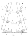
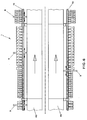
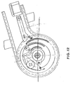
- FIG. 1 to 6 show two embodiment variants of a pharmaceutical wholesale order picking machine 1 for automatic order picking and dispatching of articles from a order picking warehouse, which has modularly constructed individual, vertically extending machine shelves 3 which are slightly inclined upwards and backwards.
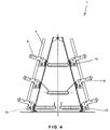
- the two embodiment variants according to FIGS. 1 to 3 and FIGS. 4 to 6 differ in the arrangement of the drive trains 13.
- the drive trains 13 lie behind the assigned machine rack rows, while in the second exemplary embodiment the machine trains 13 directly into the Vending machine rack rows are provided at the bottom of each push-out level.
- a single article column or a plurality of article columns of different products lying one on top of the other can be accommodated in each individual machine shelf 3, which has a loading height of 1.50 m to 1.75 m.
- Each article column is assigned pushers 5 at the lowest point, which according to FIGS. 1 to 6 are in different pushing-out levels A, B and C.
- the pushers 5 have a narrow and flat design and can be arranged to be movable and also stationary, as will be described below.
- the individual machine shelves 3, which are of modular height, are arranged side by side in a row, three shelf modules D, E and F being arranged one behind the other according to the exemplary embodiment in FIGS. 1 to 3.
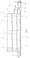
- individual conveyor belts 41 are also provided for the higher push-out levels B and C, and two conveyor belts 40 running parallel to one another at the lowest push-out level A.
- the aforementioned conveyor belts 40, 41 have a horizontal length approximately the length of a shelf module D, E and F, as can be seen in FIGS. 2 and 3, and are inclined slightly at an angle to one another. They overlap in the connection area in order to transport picked articles ejected by individual stationary pushers 5 or by movable pushers 5 to the conveyor belt end point G and from there via straight and / or inclined connecting conveyor belts 39 to a central discharge point H. At the discharge point H, the picked articles are conveyed to a clocked order container 38 and from there to a packaging point.
- the individual modular shelves A, B and C are firmly connected to each other, just as the individual shelf modules D, E and F are firmly connected to each other, in particular screwed.
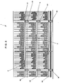
- the driving torque is therefore divided by the transfer case onto the individual continuous drive trains 13 (in the illustrated case three on each side).
- These continuous drive trains 13 rotate continuously and drive the collecting conveyor belts via a gear.
- these pushers are actuated or their toothed belt conveyor belts 4, as will be described below, by actuating special couplings in individual stationary pushers 5. Since a central drive 42 is provided in a space-saving manner in the space which is favorable per se between the two rows of automatic shelves for the entire order-picking system 1, the working speed can be adjusted with a frequency converter. Instead of drive trains 13 extending over the entire sum of rack modules D, E and F, drive trains can also be provided in the length of the individual rack modules D, E and F, which are connected to one another by fixed couplings.
- moveable ejectors 5, ie axially displaceable on the drive trains 13, can be provided.
- the portable pushers 5 are not assigned to an individual machine shelf, but to a machine shelf row or an area of the machine shelf row and, if necessary, can be positioned with an individual machine shelf in order to have an article contained therein as needed to be removed in case.
- a transmission drive in the form of a toothed belt drive 50 is provided, which is assigned to a specific pusher 5 and fastened to it.
- the toothed belt drive 50 is in turn driven by a regulating drive 51 in order to position the pusher at the desired location.
- control drives of several push-out levels A, B, C can be arranged directly one above the other, as can be seen in particular in FIG. 5.
- Two adjacent toothed belt drives 50 of the same push-out plane A, B or C can be designed as a compact control drive unit (cf. FIG. 5).
- the pusher 5 has a toothed belt-driven conveyor belt 4, which has pusher cams 30 that are equally spaced on the outside.
- the conveyor belt 4 is driven by a gear 6 according to FIG. 7 in a counterclockwise direction, which in turn meshes with a lower-lying pinion 12, which is fixed in place or axially displaceably by means of a tongue and groove connection on an elongated common drive shaft 13 at a corresponding point.
- the drive shaft 13 is driven by a central drive, for example by an electric motor, which consequently drives all the individual pushers of a commissioning system 1, the torque in a transfer case also on a plurality of elongated drive shafts can be divided if this provides for the design of a larger order picking system 1.
- the common drive drives the conveyor belts, which transport the commissioned items that have been pushed out to a shipping point.
- the working speed of the central drive can be adjusted with a frequency converter.
- Each individual pusher 5 comprises a toothed belt conveyor belt 4 with preferably three pusher cams 30 which have a damping piece in order to set up a damped initial stop on an article to be pushed out at the lowest point of an article column 2.
- the conveyor belt 4 has in particular a driven gear 6 which meshes with the toothed belt of the conveyor belt 4 and which is significantly larger than the other non-driven conveyor belt deflection roller or rail 7, with the driven gear 6 being assigned a further deflection roller or rail 8 on the underside a conveyor belt wrap angle of almost 270 ° is set for the driven gear 6.
- the upper conveyor belt section 9 runs parallel to the lower conveyor belt section 10, and the article section 2 of the order-picking rack 3 is assigned to the parallel section of the conveyor belt 4 on the upper side.
- the upper and lower conveyor belt runs 9, 10 are comparatively closely spaced from one another, so that a low overall height is set up in the critical area of a picking rack.
- pushers can be arranged in different pushing-up levels in a space-saving manner, not only at the lowest point, as is possible in the prior art.
- the magazine height can be selected in small increments for each article, taking into account the turnover of the article and the ratio of its own weight to the strength of the packaging. This ratio must not exceed a certain level, so that the article below is not overwhelmed by the article column above.
- the ejector 5 is located overall in a housing 29, in which in particular the pinion 12 driven by the drive shaft 13, the driven gear 6, the conveyor belt 4, the deflection rollers or rails 7, 8 and the electromagnet 15 are arranged.
- the housing 29 has, in particular in the region of the upper side of the upper conveyor belt run 9, a cutout through which the push-out cams 30 can come into engagement with an article to be pushed out during rotation.
- a hold-down device 31 is also provided which, when a picked article is pushed out, feeds the latter to a conveyor belt in a defined manner.
- a counter switch 32 Also provided in or on the housing is a counter switch 32, the resilient tongue 33 of which is depressed when an article is pushed out and thereby actuates the counter switch 32 by a counting step.
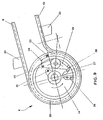
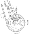
- the driven gear 6 is constructed in particular in accordance with FIGS. 8 to 14 and is very compact narrow construction, as can be seen in particular in FIG. 8. Due to the very narrow design of the driven gear 6, very narrow pushers 5 can also be realized overall, which are not only simple to manufacture and very reliable in operation, but can also be used for very narrow picking items. If wider articles or article columns 2 are specified, two or more pushers can be arranged side by side for a single article column, which are controlled synchronously.
- the driven gear 6 comprises a first ring gear 14 which meshes with the driven pinion 12. Furthermore, the driven gear 6 comprises a second ring gear 25 which meshes with the toothed belt of the conveyor belt 4. Both ring gears 14, 25 are connected to one another via a coupling part which can be switched by the electromagnet 15.
- the clutch comprises a pawl 24 pivotably articulated on the first ring gear 14, as is shown in greater detail in FIG. 9.
- the pawl 24 is associated with a spring catch 26 which is likewise fastened to the first ring gear 14 and which has two catch positions 27, 28, by means of which the switch pawl is held in the currently switched position (clutch on or clutch off), unless the switching process is currently being carried out .
- the pawl 24 of FIG. 9 is in the clutch switch position. 9, the pawl 24 moves clockwise and is then in engagement with the locking portion 34 of the second ring gear 25, which is in engagement with the toothed belt of the conveyor belt 6.
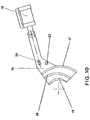
- the pawl is actuated by its switching pin 20 which, when the first ring gear 14 rotates Clockwise against a switch-on curve 18 or against a switch-off curve 17 of the plate switching curve 16 runs, as is shown in particular in FIGS. 11 to 14.
- the plate-shaped switching curve 16 further comprises a counter-curve 19, which can come into engagement with a counter-pin 21 which, similar to the switching pin 20 on the switching pawl 24, is arranged at a radially inner location on the first ring gear 14.
- the plate-shaped switching curve 16 has, in particular, spaced-apart crescent-shaped individual curves 17, 18, 19 which, in a plan view according to FIG. 10, lie approximately in a sector area of the driven gear 6 of approximately 90 °.
- the individual curves 17, 18 and 19 are spaced differently from one another at the ends and are designed like ramps.
- the pawl 24 is in the position shown in FIG. 9, ie in the clutch off position.
- the platy switching curve 16 is in its end position on the left in FIG. 1, ie in the switching curve position.
- the central drive shaft 13 can therefore normally rotate, but the ejector is not taken along. Only the inner part of the magnetic coupling rotates, ie the first ring gear 14 on which the pawl 24 is located.
- the switching cam position "on" can be set as shown in FIG. 9 by actuating the electromagnet 15.
- the caster lock 22, 23 is released and at the same time all the individual curves 17, 18 and 19 of the plate switching curve 16 are shifted slightly to the right as shown in FIG.
- the end position is determined by the guide pin 35. In this switching curve position, when the first ring gear 14 rotates, the counter pin 21 can come into engagement with the radial inside of the counter curve 19 of the plate switching curve 16.
- the switching pin 20 of the pawl 24 moves into engagement with the radial outside of the middle switch-in curve 18, the upper end of which is radially further away from the center of the driven gear 6 than the lower-side entry end.
- the switching pin 20 is therefore moved radially outwards in a ramp-like manner, and the switching pawl 24 comes radially outwards in the area of the switching pin 20 and therefore engages with the locking region 34 of the second ring gear 25.
- a wear-reducing damping element or a resilient yielding element can be interposed.
- the switching pawl 24 therefore assumes the locking position shown in FIGS. 12 and 13.
- the fact that the counter pin 21 on the radially inner side of the counter cam 19 is passed by engaging prevents the weak switching magnet from being retracted into its original position by the inertia of the switching pawl and by the holding force of the spring catch 26.
- the clutch is disengaged analogously according to Fig. 14. If the counter pin 21 has left the radial inside of the counter curve 19, the plate-type switching curve 16 can be pushed into the position shown in FIG. 14, in which the individual curves 17, 18 and 19 are closer to the center of the driven gear 6 (and the caster lock 22, 23 has been put back into operation).
- the switching pin 20 comes against the radial inside of the switch-off curve 17. Since the upper end of the switch-off curve 17 is located radially closer to the center of the driven gear 6 than the lower end of the switch-off curve 17, the switch pawl 24 is pivoted counterclockwise with respect to the first ring gear 14 , so that the pawl 24 comes out of an engagement of the locking portion 34 of the second ring gear 25.
- the pawl 24 ultimately resumes the starting position shown in FIG. 11. Characterized in that the counter pin 21 is engaged when switching the pawl in its release position on the radial outside of the counter curve 19, prevents the weak switching magnet from being retracted into its original position by the inertia of the pawl and by the holding force of the spring catch.
- the switching curve 16 can only be moved by the magnet when the rotating counter pin 21 is not in the sector of the counter curve 19. This means that the magnet must already be switched over in the range 90 to 360 ° before the pawl 24 engages or disengages.
Landscapes
- Engineering & Computer Science (AREA)
- Mechanical Engineering (AREA)
- Warehouses Or Storage Devices (AREA)
- Vending Machines For Individual Products (AREA)
- De-Stacking Of Articles (AREA)
Claims (10)
- Système automatique (1) de préparation de commandes de commerce en gros de produits pharmaceutiques destiné à réaliser automatiquement et rapidement le rassemblement et la préparation pour l'expédition d'articles avec un volume de plus de 30.000 lignes de commande par jour, à partir d'une multiplicité d'articles situés dans un entrepôt de marchandises à expédier, comportant des magasins (3), disposés en rangées et sensiblement verticaux, qui peuvent être équipés de colonnes (2) d'articles et auxquels sont associés en bas des poussoirs (5), caractérisé en ce qu'il est prévu non seulement un poussoir (5), stationnaire, mais aussi un poussoir (5), qui est amovible et peut être déplacé axialement dans l'extension longitudinale du système automatique de préparation de commandes et qui est adjoint à plusieurs magasins (3) et peut être positionné pour l'un de ces magasins individuels.
- Système automatique de préparation de commandes de commerce en gros de produits pharmaceutiques selon la revendication 1, caractérisé en ce que les poussoirs (5) déplaçables axialement sont adjoints à des plans de ramassage (A, B, C) différents.
- Système automatique de préparation de commandes de commerce en gros de produits pharmaceutiques selon l'une des revendications 1 et 2, caractérisé en ce qu'au moins deux rangées de magasins sont disposées dos à dos, en étant légèrement inclinées l'une par rapport à l'autre en forme de A en vue frontale, deux bandes transporteuses parallèles (40), destinées à recueillir les articles préparés par les poussoirs (5), étant associées à chaque plan de ramassage inférieur (A) entre les rangées de magasins, une bande transporteuse correspondante (41) étant associée à chacun des plans de ramassage supérieurs (B, C).
- Système automatique de préparation de commandes de commerce en gros de produits pharmaceutiques selon la revendication 3, caractérisé en ce qu'un dispositif d'entraînement central (42) pour les poussoirs (5) et les bandes transporteuses (40, 41) est prévu entre les rangées de magasins, le dispositif d'entraînement central étant relié en rotation à des lignes d'arbre de transmission (13), d'axes parallèles, qui sont associées aux différents plans de ramassage (A, B, C) et se trouvent dans la région des plans de ramassage (voir figures 1 et 4).
- Système automatique de préparation de commandes de commerce en gros de produits pharmaceutiques selon la revendication 4, caractérisé en ce que les poussoirs amovibles sont solidaires en rotation, mais cependant coulissants, le long des lignes d'arbre de transmission (13).
- Système automatique de préparation de commandes de commerce en gros de produits pharmaceutiques selon la revendication 5, caractérisé en ce qu'un dispositif de transmission est prévu le long des lignes d'arbre de transmission (13) pour un poussoir amovible (5) associé, le dispositif de transmission étant une transmission à courroie dentée (50) qui est reliée au poussoir (5) et qui peut être entraînée et positionnée par un entraînement asservi (51) (voir figures 5 et 6).
- Système automatique de préparation de commandes de commerce en gros de produits pharmaceutiques selon la revendication 6, caractérisé en ce que les entraînements asservis (51) relatifs à plusieurs plans de ramassage sont disposés les uns au-dessus des autres (voir figure 5).
- Système automatique de préparation de commandes de commerce en gros de produits pharmaceutiques selon la revendication 6 ou 7, caractérisé en ce que les deux entraînements asservis (51) de dispositifs de transmission horizontalement voisins d'un plan de ramassage (A, B ou C) sont réalisés sous la forme d'une unité d'entraînement asservi (voir figure 5).
- Système automatique de préparation de commandes de commerce en gros de produits pharmaceutiques selon l'une quelconque des revendications 1 à 8, caractérisé en ce qu'il est prévu des poussoirs (5) étroits, de construction aplatie (voir figures 7, 8).
- Système automatique de préparation de commandes de commerce en gros de produits pharmaceutiques selon l'une quelconque des revendications 3 à 9, caractérisé en ce que, pendant l'exploitation du système automatique (1) de préparation de commandes, le dispositif d'entraînement central (42) entraîne en continu les brandes transporteuses (40, 41), et le poussoir (5) associé à un article à ramasser peut être mis en marche par l'intermédiaire d'un accouplement magnétique (voir figures 8 à 14).
Priority Applications (1)
| Application Number | Priority Date | Filing Date | Title |
|---|---|---|---|
| AT90102935T ATE72654T1 (de) | 1989-06-19 | 1990-02-15 | Kommissionierautomat zur automatischen kommissionierung und versandbereitstellung von artikeln. |
Applications Claiming Priority (2)
| Application Number | Priority Date | Filing Date | Title |
|---|---|---|---|
| DE8907478U | 1989-06-19 | ||
| DE8907478U DE8907478U1 (de) | 1989-06-19 | 1989-06-19 | Kommissionierautomat zur automatischen Kommissionierung und Versandbereitstellung von Artikeln |
Publications (3)
| Publication Number | Publication Date |
|---|---|
| EP0403726A1 EP0403726A1 (fr) | 1990-12-27 |
| EP0403726B1 EP0403726B1 (fr) | 1992-02-19 |
| EP0403726B2 true EP0403726B2 (fr) | 1995-11-15 |
Family
ID=6840256
Family Applications (1)
| Application Number | Title | Priority Date | Filing Date |
|---|---|---|---|
| EP90102935A Expired - Lifetime EP0403726B2 (fr) | 1989-06-19 | 1990-02-15 | Aménagement d'entrepôt pour le ramassage automatique et la préparation de commandes ordonnées d'articles |
Country Status (4)
| Country | Link |
|---|---|
| EP (1) | EP0403726B2 (fr) |
| AT (1) | ATE72654T1 (fr) |
| DE (2) | DE8907478U1 (fr) |
| ES (1) | ES2030305T3 (fr) |
Families Citing this family (11)
| Publication number | Priority date | Publication date | Assignee | Title |
|---|---|---|---|---|
| DE3929656A1 (de) * | 1989-09-06 | 1991-03-07 | Knapp Guenter Gmbh Co Kg | Verfahren und vorrichtung zum lagern in und zum automatischen entnehmen von stueckgutsorten aus regalen in grosslagern |
| DE9203273U1 (de) * | 1992-03-11 | 1992-09-03 | Wiltsche GmbH Logistik Engineering Automation, 8228 Freilassing | Kommissionierautomat zur automatischen Kommissionierung von Artikeln |
| DE4225041A1 (de) * | 1992-07-29 | 1994-02-03 | Priparop S A | Kommissionieranlage |
| US5678680A (en) * | 1994-04-13 | 1997-10-21 | Sft Ag Spontanfoerdertechnik | Method and arrangement for producing consolidated lines of products |
| FR2804097B1 (fr) * | 2000-01-21 | 2002-03-22 | Tabacs & Allumettes Ind | Systeme de distribution automatique d'articles pour la preparation d'une ou plusieurs commandes de tels articles |
| DE10012942A1 (de) | 2000-03-19 | 2001-10-04 | Knapp Logistik Automation | Kommissioniervorrichtung mit in einem Regal angeordneten Produktspeichern und positionierbarer Ausschiebereinheit |
| DE102006007364A1 (de) * | 2006-02-17 | 2007-08-23 | Knapp Logistik Automation Ges.M.B.H. | Verfahren und Zentralbandautomat zum Befüllen eines Auftragsbehälters in einem Kommissioniersystem |
| DE102008037658A1 (de) | 2008-08-14 | 2010-02-25 | Knapp Logistik Automation Gmbh | Verfahren und Vorrichtung zum Kommissionieren von Stückgut mit einem Kommissionierautomaten und beigeordnetem Durchlaufregal |
| DE102008037657A1 (de) * | 2008-08-14 | 2010-02-25 | Knapp Logistik Automation Gmbh | Verfahren und Vorrichtung zum manuellen Kommissionieren von Stückgut mit einem Durchlaufregal |
| DE202009003672U1 (de) | 2009-03-17 | 2009-05-28 | SSI Schäfer PEEM GmbH | Kommissionierautomat mit verfahrbaren Auswerfern |
| DE102012102075A1 (de) * | 2012-03-12 | 2013-09-12 | Kardex Produktion Deutschland Gmbh | Lager, insbesondere Kommissionierungslager sowie Lagerverwaltungssystem und Verfahren für dessen Betrieb |
Family Cites Families (2)
| Publication number | Priority date | Publication date | Assignee | Title |
|---|---|---|---|---|
| AU453471B2 (en) * | 1971-06-03 | 1974-09-16 | Elecompack Company Limited | Apparatus for storing and delivering articles |
| AT385492B (de) * | 1985-08-06 | 1988-04-11 | Pem Foerderanlagen Ges M B H | Vorrichtung zum automatischen entnehmen von stueckgut aus vorratsmagazinen |
-
1989
- 1989-06-19 DE DE8907478U patent/DE8907478U1/de not_active Expired
-
1990
- 1990-02-15 EP EP90102935A patent/EP0403726B2/fr not_active Expired - Lifetime
- 1990-02-15 DE DE9090102935T patent/DE59000046D1/de not_active Expired - Lifetime
- 1990-02-15 ES ES199090102935T patent/ES2030305T3/es not_active Expired - Lifetime
- 1990-02-15 AT AT90102935T patent/ATE72654T1/de not_active IP Right Cessation
Also Published As
| Publication number | Publication date |
|---|---|
| ES2030305T3 (es) | 1992-10-16 |
| DE8907478U1 (de) | 1989-08-03 |
| EP0403726A1 (fr) | 1990-12-27 |
| EP0403726B1 (fr) | 1992-02-19 |
| DE59000046D1 (de) | 1992-03-26 |
| ATE72654T1 (de) | 1992-03-15 |
Similar Documents
| Publication | Publication Date | Title |
|---|---|---|
| EP1795464B1 (fr) | Étagère pour le commerce au détail | |
| EP0271042B1 (fr) | Procédé d'emballage et automate d'emballage pour enveloppes pour lettres et pochettes d'expédition | |
| EP0403726B2 (fr) | Aménagement d'entrepôt pour le ramassage automatique et la préparation de commandes ordonnées d'articles | |
| AT13828U1 (de) | Kommissioniersystem und Verfahren zur Beladung von Ladungsträgern | |
| DE3213119A1 (de) | Verfahren und vorrichtung zum automatischen stapeln, lagern und entnehmen von stueckgut | |
| EP0312490B1 (fr) | Procédé et dispositif pour former et transporter des groupes de produits alimentaires plats empilables, en particulier des biscuits | |
| EP2143667B1 (fr) | Dispositif de stockage pour marchandises et procédé correspondant | |
| DE3700506C2 (fr) | ||
| DE69009983T2 (de) | Vorrichtung und Verfahren zum Handhaben von Waren. | |
| EP1423314B1 (fr) | Magasin a rayonnage comportant des tiroirs montes dans les compartiments de rayonnage | |
| AT501897A4 (de) | Verfahren und vorrichtung zum automatischen beschicken einer warenausgabeeinrichtung | |
| AT402393B (de) | Kommissioniereinrichtung | |
| EP0684196B1 (fr) | Dispositif de groupage, de transport et de stockage | |
| DE929283C (de) | Kartenausstossvorrichtung fuer Lochkartenmaschinen | |
| AT403156B (de) | Regalsystem | |
| EP2557056B1 (fr) | Système de stockage avec appareil à longeron | |
| EP1144282B1 (fr) | Dispositif pour rassembler et preparer des marchandises de detail | |
| DE68926110T2 (de) | Verwaltungssystem und verfahren für eine rotierende lagerungsstruktur | |
| EP0369060A1 (fr) | Aménagement d'entrepôt pour le ramassage automatique et la préparation de commandes ordonnées d'articles | |
| EP1462395B1 (fr) | Tampon intermédiaire | |
| EP0991036B1 (fr) | Distributeur | |
| EP0370121B2 (fr) | Poussoir d'alimentation dans un entrepÔt automatisé | |
| DE20304880U1 (de) | Zwischenspeicher | |
| DE10015272C2 (de) | Vorrichtung zum Ein- und Auslagern von Laststrägern in einem Regallager | |
| EP0560206B1 (fr) | Aménagement d'entrepÔt pour le ramassage automatique d'articles |
Legal Events
| Date | Code | Title | Description |
|---|---|---|---|
| PUAI | Public reference made under article 153(3) epc to a published international application that has entered the european phase |
Free format text: ORIGINAL CODE: 0009012 |
|
| AK | Designated contracting states |
Kind code of ref document: A1 Designated state(s): AT BE CH DE DK ES FR GB GR IT LI LU NL SE |
|
| 17P | Request for examination filed |
Effective date: 19901214 |
|
| 17Q | First examination report despatched |
Effective date: 19910719 |
|
| GRAA | (expected) grant |
Free format text: ORIGINAL CODE: 0009210 |
|
| AK | Designated contracting states |
Kind code of ref document: B1 Designated state(s): AT BE CH DE DK ES FR GB GR IT LI LU NL SE |
|
| PG25 | Lapsed in a contracting state [announced via postgrant information from national office to epo] |
Ref country code: GR Free format text: LAPSE BECAUSE OF FAILURE TO SUBMIT A TRANSLATION OF THE DESCRIPTION OR TO PAY THE FEE WITHIN THE PRESCRIBED TIME-LIMIT Effective date: 19920219 Ref country code: FR Effective date: 19920219 Ref country code: DK Effective date: 19920219 Ref country code: GB Effective date: 19920219 Ref country code: SE Effective date: 19920219 Ref country code: NL Effective date: 19920219 |
|
| REF | Corresponds to: |
Ref document number: 72654 Country of ref document: AT Date of ref document: 19920315 Kind code of ref document: T |
|
| REF | Corresponds to: |
Ref document number: 59000046 Country of ref document: DE Date of ref document: 19920326 |
|
| ITF | It: translation for a ep patent filed | ||
| ET | Fr: translation filed | ||
| GBT | Gb: translation of ep patent filed (gb section 77(6)(a)/1977) | ||
| NLV1 | Nl: lapsed or annulled due to failure to fulfill the requirements of art. 29p and 29m of the patents act | ||
| REG | Reference to a national code |
Ref country code: ES Ref legal event code: FG2A Ref document number: 2030305 Country of ref document: ES Kind code of ref document: T3 |
|
| PLBI | Opposition filed |
Free format text: ORIGINAL CODE: 0009260 |
|
| 26 | Opposition filed |
Opponent name: KNAPP LOGISTIK AUTOMATION GES.M.B.H. Effective date: 19921119 Opponent name: LISTA GMBH + CO. Effective date: 19921119 |
|
| EPTA | Lu: last paid annual fee | ||
| PGFP | Annual fee paid to national office [announced via postgrant information from national office to epo] |
Ref country code: LU Payment date: 19950201 Year of fee payment: 6 |
|
| PGFP | Annual fee paid to national office [announced via postgrant information from national office to epo] |
Ref country code: GB Payment date: 19950206 Year of fee payment: 6 |
|
| PGFP | Annual fee paid to national office [announced via postgrant information from national office to epo] |
Ref country code: FR Payment date: 19950215 Year of fee payment: 6 |
|
| PGFP | Annual fee paid to national office [announced via postgrant information from national office to epo] |
Ref country code: ES Payment date: 19950220 Year of fee payment: 6 |
|
| PGFP | Annual fee paid to national office [announced via postgrant information from national office to epo] |
Ref country code: BE Payment date: 19950306 Year of fee payment: 6 |
|
| PUAH | Patent maintained in amended form |
Free format text: ORIGINAL CODE: 0009272 |
|
| STAA | Information on the status of an ep patent application or granted ep patent |
Free format text: STATUS: PATENT MAINTAINED AS AMENDED |
|
| 27A | Patent maintained in amended form |
Effective date: 19951115 |
|
| AK | Designated contracting states |
Kind code of ref document: B2 Designated state(s): AT BE CH DE DK ES FR GB GR IT LI LU NL SE |
|
| REG | Reference to a national code |
Ref country code: CH Ref legal event code: AEN Free format text: AUFRECHTERHALTUNG DES PATENTES IN GEAENDERTER FORM |
|
| PG25 | Lapsed in a contracting state [announced via postgrant information from national office to epo] |
Ref country code: LU Free format text: LAPSE BECAUSE OF NON-PAYMENT OF DUE FEES Effective date: 19960215 |
|
| PG25 | Lapsed in a contracting state [announced via postgrant information from national office to epo] |
Ref country code: ES Free format text: LAPSE BECAUSE OF THE APPLICANT RENOUNCES Effective date: 19960216 |
|
| PG25 | Lapsed in a contracting state [announced via postgrant information from national office to epo] |
Ref country code: BE Free format text: LAPSE BECAUSE OF NON-PAYMENT OF DUE FEES Effective date: 19960229 |
|
| EN | Fr: translation not filed | ||
| GBV | Gb: ep patent (uk) treated as always having been void in accordance with gb section 77(7)/1977 [no translation filed] |
Effective date: 19950219 |
|
| REG | Reference to a national code |
Ref country code: ES Ref legal event code: FD2A Effective date: 19991102 |
|
| REG | Reference to a national code |
Ref country code: CH Ref legal event code: PUE Owner name: WILTSCHE GMBH TRANSFER- P+P MATERIALFLUSS-SYSTEME Ref country code: CH Ref legal event code: NV Representative=s name: SCHMAUDER & PARTNER AG PATENTANWALTSBUERO |
|
| PG25 | Lapsed in a contracting state [announced via postgrant information from national office to epo] |
Ref country code: IT Free format text: LAPSE BECAUSE OF NON-PAYMENT OF DUE FEES;WARNING: LAPSES OF ITALIAN PATENTS WITH EFFECTIVE DATE BEFORE 2007 MAY HAVE OCCURRED AT ANY TIME BEFORE 2007. THE CORRECT EFFECTIVE DATE MAY BE DIFFERENT FROM THE ONE RECORDED. Effective date: 20050215 |
|
| PGFP | Annual fee paid to national office [announced via postgrant information from national office to epo] |
Ref country code: AT Payment date: 20090219 Year of fee payment: 20 |
|
| PGFP | Annual fee paid to national office [announced via postgrant information from national office to epo] |
Ref country code: CH Payment date: 20090223 Year of fee payment: 20 |
|
| REG | Reference to a national code |
Ref country code: CH Ref legal event code: PCAR Free format text: SCHMAUDER & PARTNER AG PATENT- UND MARKENANWAELTE VSP;ZWAENGIWEG 7;8038 ZUERICH (CH) |
|
| PGFP | Annual fee paid to national office [announced via postgrant information from national office to epo] |
Ref country code: DE Payment date: 20090430 Year of fee payment: 20 |
|
| REG | Reference to a national code |
Ref country code: CH Ref legal event code: PL |
|
| PG25 | Lapsed in a contracting state [announced via postgrant information from national office to epo] |
Ref country code: DE Free format text: LAPSE BECAUSE OF EXPIRATION OF PROTECTION Effective date: 20100215 |