EP0403529B1 - Compression a mode mixte pour la transmission de donnees - Google Patents
Compression a mode mixte pour la transmission de donnees Download PDFInfo
- Publication number
- EP0403529B1 EP0403529B1 EP89903318A EP89903318A EP0403529B1 EP 0403529 B1 EP0403529 B1 EP 0403529B1 EP 89903318 A EP89903318 A EP 89903318A EP 89903318 A EP89903318 A EP 89903318A EP 0403529 B1 EP0403529 B1 EP 0403529B1
- Authority
- EP
- European Patent Office
- Prior art keywords
- information
- compression
- mode
- node
- link
- Prior art date
- Legal status (The legal status is an assumption and is not a legal conclusion. Google has not performed a legal analysis and makes no representation as to the accuracy of the status listed.)
- Expired - Lifetime
Links
Images


Classifications
-
- H—ELECTRICITY
- H04—ELECTRIC COMMUNICATION TECHNIQUE
- H04J—MULTIPLEX COMMUNICATION
- H04J3/00—Time-division multiplex systems
- H04J3/17—Time-division multiplex systems in which the transmission channel allotted to a first user may be taken away and re-allotted to a second user if the first user becomes inactive, e.g. TASI
- H04J3/172—Digital speech interpolation, i.e. DSI
-
- H—ELECTRICITY
- H04—ELECTRIC COMMUNICATION TECHNIQUE
- H04J—MULTIPLEX COMMUNICATION
- H04J3/00—Time-division multiplex systems
- H04J3/18—Time-division multiplex systems using frequency compression and subsequent expansion of the individual signals
Definitions
- the present invention relates to communication networks through which compressed data is transmitted.
- an integrated digital network employing mixed compression modes for speech is disclosed.
- a call from telephone 1 enters a network at point A, and is passed through speech processing equipment 2 at point A.
- the call is then transmitted in a compressed mode across a link 3, to point B, where conjugate speech processing equipment 4 decodes the compressed data to recover the original signals and supplies them in a mode compatible with the receiving station 5.
- Such networks are provided by multiple integrated digital network exchange switches such as those provided by Network Equipment Technologies, Inc., the assignee of the present invention.
- Such networks allow speech signals entering the network from a first station 6, to enter speech processing equipment 7 at point A, and to be passed in a compressed mode through link 8 to point X, where equipment 9 transmits the compressed data on link 10 to point Y.
- equipment 11 transmits the compressed data on link 12 to point Z, where equipment 13 transmits the compressed data on link 14 to point B.
- conjugate speech expansion equipment 15 reconstitutes the original speech signal which is then delivered to the receiving station 16.
- the parameters are read and the speech decoded according to the same dynamic compression algorithm.
- Irvin addresses the problem of making efficient use of transmission resources by adapting the coding rate for PCM speech signals.
- end-to-end system it illustrates the problem addressed by the present invention. That is, all receiving stations must have equipment capable of decoding the data from the adaptive PCM formats.
- the present invention provides a method and apparatus for mixed-mode compression within a single network for data transmission.
- an apparatus for communicating information among a network of stations for sending and receiving the information comprising; a plurality of switching nodes ; a plurality of links connecting the switching nodes in a communication network, the links including means for transmitting channels of coded information between neighboring nodes; at least a first node of the switching nodes comprising station port means, coupled to a station, for communicating information to and from the station, link port means, coupled to a link, for communicating channels to and from the link, connecting means, coupled to the station port means and the link port means, for connecting selected information or channels to a selected one of the station port means or the link port means for transmission on a selected link or to a selected station, and coding means, coupled to the station port means and the connecting means, for coding the information from a station according to a selected one of a plurality of compression algorithms for transmission in a channel in one of a plurality of compression modes corresponding to the selected compression algorithm, the selected one compression algorithm being determined by a desired compression mode for transmission
- the apparatus preferably comprises a plurality of access and switching nodes and a plurality of links connecting the access and switching nodes in a communication network.
- the links include means for transmitting channels of coded information between the nodes to which they are connected.
- the access nodes comprise a station port coupled to a station for communicating information to and from the station, a link port coupled to a link for communicating channels to and from the link, connecting means coupled to the station port and link port, for connecting selected information or channels to a selected one of the station ports or link ports for transmission on a selected link or to a selected station, coding means coupled to the station port and the connecting means, for coding the information from a station according to a preselected one of a plurality of compression modes for transmission in a channel, and decoding means, coupled to the link port and the connecting means, for decoding information in a channel according to a preselected one of the plurality of compression modes for communicating the information to the station.
- the switching nodes comprise a plurality of link ports, each coupled to at least one link, for communicating channels to and from the links, connecting means, coupled to the link ports, for connecting selected channels to one of the plurality of link ports in the switching node for transmission on a selected link, and coding means, coupled to the link port and the connecting means, for coding the information in a channel according to a selected one of the plurality of compression modes for transmission of the information in a channel across a link.
- a method for transmitting information through a communication network comprising the steps of: receiving information at a first node in a first mode, coding the information according to a first compression algorithm to a second mode and transmitting the information in the second mode to a second node, receiving at the second node the information in the second mode, coding the information according to a second compression algorithm to a third mode and transmitting the information in the third mode to a third node.
- the mode of compression of a channel of. speech information is determined by the ports through which it is transmitted.
- the mode of compression of the data is determined and the data is coded according to that mode.
- the mode of compression of data is determined and the data is processed accordingly.
- speech from telephone station 30 may enter the network at point A where equipment 31 transmits the speech in a first mode, such as full pulse code modulation, having a bandwidth of 64 kilobits per second to node B, through intermediate nodes 32 if necessary.
- equipment 33 transmits the data in a second mode of compression such as adaptive differential pulse code modulation (ADPCM), through intermediate nodes 34 if necessary.
- ADPCM adaptive differential pulse code modulation
- the bit rate is reduced to 32 kilobits per second for reception at node C.
- equipment 35 employs a third mode of compression, such as digital speech interpolation (DSI).
- DSI digital speech interpolation
- Transmission then takes place through the network in the third compression mode having an effective bit rate of 32 kilobits per second, though interleaved with other speech signals, to node D, and again through as many intermediate nodes 36 as necessary.
- equipment 37 supplies the inverse DSI function to return the signal to ADPCM at 32 kilobits per second for transmission through the network (intermediate nodes 38, if necessary,) to node E.
- equipment 39 supplies the inverse ADPCM function to return the signal to full bandwidth PCM at 64 kilobits per second for transmission through the network (intermediate nodes 40, if necessary,) to node F where equipment 41 delivers the speech signal to the user.
- an ADPCM compression may be invoked at the point of entrance, node A, or point of exit, node F. It is equally acceptable for ADPCM and DSI compression to be coincident in node C or D, for example, or both. Further, full four-to-one compression can be invoked at either or both of the entry and exit nodes A or F.
- all of this is done automatically, according to pre-established compression and transmission preferences for each circuit, utilizing resources available at the time the circuit is established in the network. Since compression equipment and transmission paths are assigned at call placement time, it is therefore possible for identical calls placed through the network at different times to have no compression applied, 2:1 ADPCM, or 4:1 ADPCM/DSI, depending on the availability of compression resources in the particular path chosen through the network for the call.
- the mixed mode compression of the present invention allows networks to be built that employ 4:1 compression on high traffic density backbone links in the core of a network, while 2:1 compression is employed simultaneously in the outer less dense layers, and no compression is used in the outermost, low density access links. This can result in significant savings in both initial equipment cost and ongoing operational cost.
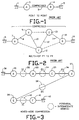
- Fig. 1 is a heuristic diagram of a prior art point-to-point network.
- Fig. 2 is a heuristic diagram of a prior art multi-hop point-to-point network.
- Fig. 3 is a heuristic diagram of a network according to the present invention, employing mixed-mode compression.
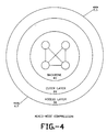
- Fig. 4 is a conceptual diagram of a multiple layer network employing mixed-mode compression according to the present invention.
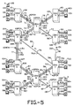
- Fig. 5 is a block diagram of a network according to the present invention employing ten integrated digital network exchange switches with multiple modes of compression.
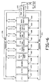
- Fig. 6 is a block diagram of an integrated digital network exchange according to the present invention.
- Fig. 7 is a flowchart of a control algorithm for an integrated digital network exchange originating a call.
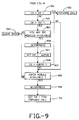
- Figs. 8 and 9 are a flowchart of a control algorithm for an integrated digital network exchange forwarding a call originated at a different node in the network.
- Fig. 10 is a flowchart of a control algorithm for an integrated digital network exchange at the destination of a call.
- FIG. 5 illustrates an example of a network for communicating data having ten integrated digital network exchanges (IDNX1-IDNX-10), implementing multi-mode compression according to the present invention.
- IDNX1-IDNX-10 integrated digital network exchanges
- the physical interconnection of IDNX1 through IDNX10 and the stations supplying data to the network is described.
- the architecture of the IDNX exchanges is described with reference to Fig. 6.
- an example of the operation of the network using mixed-mode compression is set out with control algorithms for individual nodes as illustrated in Figs. 7-10.
- Fig. 5 illustrates a network configuration.
- the first exchange in the network IDNX1 includes three ports, 101, 102, 103, to stations supplying data for transmission in the network.
- Port 101 connects to a private branch exchange (PBX) 104 (or equivalent channel banks or key systems for speech coding) through which telephone calls as illustrated by block 105 are placed.
- PBX private branch exchange
- Port 102 connects to a computer 106.
- Port 103 connects to a teleconferencing system 107.
- Each of the station ports 101, 102, 103 connected to IDNX1 and those connected to the other IDNX exchanges in the network, are means for communicating coded information from a station to the exchange.
- the data is coded at 64 kilobits per second according to a pulse-code modulation scheme.
- IDNX1 also includes a port 108 to a link 50 for transmitting channels of coded data to IDNX3.
- the link 50 connected to port 108 of the IDNX1 includes two T1 trunks 70, 71, for transmission of data and coded speech according to the international T1 multiplexing standard, with 1.544 Mbits/sec. capacity.
- Speech transmitted across link 50 from IDNX1 to IDNX3 will be coded according to a selected mode of compression that is compatible with compression equipment in the respective nodes.
- IDNX1 may receive coded data from the PBX 104 through its port 101 in a full PCM mode. Data may then be compressed in IDNX1 to ADPCM for transmission across link 50.
- data incoming from IDNX3 to IDNX1 across link 50 may be received in ADPCM mode and translated to PCM for communication to the PBX station 104.
- IDNX2 includes three station ports 201, 202, 203, which are connected, respectively, to a PBX 204, a large capacity storage device for computer data 205, and a screen 206 for displaying teleconferencing information or the like. IDNX2 further includes three link ports 207, 208, 209, for communicating information across links 52, 55 and 54, respectively.
- Link 52 includes two T1 trunks 74 and 75.
- Link 54 includes two T1 trunks 77 and 78.
- Link 55 includes one T1 trunk 79.
- IDNX2 can receive concentrated data across link 52 for transmission across links 54 and 55, to other IDNX switches in the network; or, it may receive information directly from stations across ports 201, 202 or 203.
- IDNX3 includes four link ports 301, 302, 303, 304, connected, respectively, to links 50, 52, 51, 53, for communication of information in coded channels to other switching nodes in the network.
- Link 51 includes two T1 trunks 71 and 73.
- Link 53 includes one T1 trunk 76.
- IDNX4 includes two station ports 401, 402, connected, respectively, to a PBX 403 and a computer terminal 404.
- IDNX4 includes one link port 405 connected to link 51.
- IDNX5 includes three stations ports 501, 502, 503, connected, respectively, to a PBX station 504, a large capacity storage device 505, and a teleconferencing system 506.
- IDNX5 includes two link ports 507 and 508 connected, respectively, to link 53 and link 56.
- Link 56 includes one T1 trunk 80.
- IDNX6 includes three station ports 601, 602, 603, connected, respectively, to a PBX station 604, a computer terminal station 605, and a teleconferencing station 606.
- IDNX6 includes two link ports 607 connected to link 54, and 608 connected to link 57.
- Link 57 includes two T1 trunks 81 and 82.
- IDNX7 includes two station ports 701 and 702, connected, respectively, to a PBX station 703 and a computer terminal station 704.
- IDNX7 includes three link ports 705, 706, and 707 connected, respectively, to links 56, 55 and 58.
- Link 58 includes two T1 trunks 83 and 84.
- IDNX8 includes four link ports 801, 802, 803 and 804, connected, respectively, to links 57, 59, 58 and 60.
- Link 59 includes two T1 trunks 85 and 86 and link 60 includes one T1 trunk 87.
- IDNX9 includes three station ports 901, 902, 903, connected, respectively, to a PBX station 904, a high capacity data storage station 905, and a teleconference viewing station 906.
- IDNX9 includes one link port 907 connecting to link 59.
- IDNX10 includes three station ports 1001, 1002, 1003, connecting respectively to PBX station 1004, a high capacity data storage station 1005, and a teleconferencing station 1006. Also, IDNX10 includes one link port 1007, connected to link 60.
- the mixed-mode compression is carried out only for speech signals.
- the invention can be applied to any data suitable for multiple compression modes, such as may be supplied by teleconferencing systems, computers, medical imaging machines and other sources of information.
- the station ports to the IDNX blocks could be considered the access layer in which full pulse code modulation of the speech signals is transmitted from the exchange to the station.
- the outer layer in the network of Fig. 5 is illustrated by links 50, 51, the trunk 74 of link 52, trunk 77 of link 54, link 57, link 58, link 59 and link 60. In all of these links, full ADPCM compression is performed. In links 52 and 54 where one trunk in the two-trunk link is not DSI-capable, a second trunk in the link is adapted to carry ADPCM/DSI to increase network bandwidth.
- the "backbone” of the network of Fig. 5 is made up of trunk 75 of link 52, link 53, trunk 78 of link 54, link 55 and link 56 which are capable of full ADPCM/DSI compression for the very high capacity required for links in the backbone of the network.
- the IDNX includes a transport bus 650 and a control bus 651 that are controlled by a time slot interchange module 652.
- a given IDNX may include a plurality of shelves of modules such as those shown in Fig. 6, to which communication is provided through bus 653 and the time slot interchange module 652.
- the station ports in the IDNX include data ports 654 and speech ports 655.
- the speech port 655 is a standard DS-1 voice port module for managing interface between voice communications equipment, such as analog and digital PBX's, D3-D4 channel banks and the like, with the IDNX.
- the speech ports 655 work with the supervisor software running in a CPU module 657 to support dialing, telephone calls and other system management tasks required to set up a telephone communication network.
- the data ports 654 are station ports for communicating high speed data and the like to other types of stations.
- the link ports include T1 trunk ports 656 which include processing resources to receive or supply T1 multiplexed data for transmission to other nodes.
- the T1 trunk ports 656 contain logic to control the flow of information to T1 trunks. As described with reference to Fig. 5, the T1 trunks establish the links between nodes in the network.
- the trunk port 656 is the point at which a call leaves the IDNX and enters a link, or arrives from a remote node.
- the host processor for the IDNX includes a CPU module 657, a memory module 658 and a clock module 659.
- the processor through the CPU module 657 communicates control information to the control bus 651 for supply to the other modules in the system.
- User data flows from card to card through the time slot interchange module 652 under CPU program control across transport bus 650.
- the CPU module 657 runs software that controls the system. Supervisor software under control of the CPU module 657, establishes a logical end-to-end circuit called a channel for a given call. In addition, the CPU module 657 can provide input/output facilities for setting up system configuration information, monitoring activity in the system and maintenance.
- the memory module 658 communicates with CPU module across the control bus 651 and stores system software for use in the CPU module 657. In addition, the memory module 658 stores a configuration data base used by the supervision software for establishing circuits through the network.
- the clock module 659 serves as in internal timing source and can be used for network synchronization if desired.
- the clock module communicates with the other modules in the IDNX across the control bus.
- the time slot interchange (TSI) module 652 handles the transport bus switching. For each new call connection set up through a node, supervisor software programs run in the CPU module 657, direct the TSI module 652 to connect the time slots from one module in the system to cycles on the destination module adapted to receive the data. The connection can be established in both directions to set up a full duplex call.
- TSI time slot interchange
- Modules 660, 661 and 662 are speech compression processors. These modules increase the voice call capacity of the T1 trunks. Speech processor modules 660, 661 and 662 provide speech compression serving multiple channels. A voice channel requiring speech compression routes through one or more speech processor modules 660, 661, and 662 before reaching a T1 trunk module for outbound transmission.
- the voice channels are input from a speech port 654 in a 64 kilobit per second pulse code modulation format.
- the module 660 comprises an ADPCM module.
- This processor consists of a digital speech processor that accepts 64 kilobits per second of PCM input from the DS-1 module in the speech port 654.
- the digital speech processor in the module is a server of the DS-1 card. Therefore, any input from any DS-1 card in the IDNX can be routed through the digital speech processor. Further, each of the digital speech processor's output channels can be routed through different DS-1 ports as desired.
- the input to the speech processing module is the 64 kilobit per second pulse code modulation and the output is the multiple of 8 kilobits per second in an ADPCM format.
- the ADPCM channels are then coded by the CPU module for output on the T1 trunk module 656 at 32 kilobits per second. This provides a 2:1 compression of voice and voice band data signals.
- the ADPCM module 660 also handles signal expansion for an ADPCM signal being received from a remote IDNX.
- the VOX module 661 is a speech processor module which performs voice detection, dead-set processing and echo suppression of signals from the ADPCM module as a pre-processing step in digital speech interpolation (DSI). From the VOX module, signals are passed to the DSI processor module/port 662 which executes the digital speech interpolation algorithms. In a typical telephone conversation, each speaker is active only about 38 per cent of the time. DSI takes advantage of this by sharing trunk bandwidth among several speakers. Only active speakers are given bandwidth.
- the DSI processor in module 662 is tightly coupled to a T1 trunk to support the dynamic DSI compression algorithm. The bandwidth on the T1 trunk coupled to the DSI processor in module 662 can be dynamically allocated to DSI and non-DSI calls as network requirements change.
- the VOX and DSI processor modules 661, 662 can, in conjunction with the ADPCM voice processing card, provide 4:1 compression of the PCM voice channels from channel bank or digital PBX.
- the ADPCM module provides 2:1 compression of PCM voice channels.
- the use of the VOX and DSI modules upon the ADPCM output provides an additional 2:1 compression, for a total of 4:1 compression.
- One DSI module supports up to 90 PCM voice channels.
- the ADPCM module 660, VOX module 661 and DSI module 662 are not required.
- the data flow for an example call placed at point A through telephone 105 in the network of Fig. 5, to be received at point B through telephone 1008 is illustrated.
- the call will be placed through the PBX 104 and supplied in full 64 kilobit per second PCM mode to port 101 of IDNX1.
- DS-1 module in speech port 655 will transfer the data to the ADPCM speech processor module 660. From the ADPCM module 660, the data will be transferred to the T1 trunk port 656 and out across trunk 70 to IDNX 3.
- IDNX3 will receive the data in a trunk port 656 and transfer it to the VOX and DSI speech processor modules 661, 662.
- the VOX and DSI speech processor modules 661, 662 it is compressed in the DSI format for transmission on trunk 76 to IDNX5.
- IDNX5 will receive the data in port 507 at a T1 trunk port module 656 and pass the data through to port 508 to the T1 trunk 80.
- Data will be received in IDNX7 at port 705 in the T1 trunk port module 656 and transferred to the VOX and DSI speech processor modules 661, 662.
- the data will be expanded to the ADPCM mode and connected to port 707 for transmission across trunk 83.
- IDNX8 data will be passed from the trunk port connected to trunk 83 through port 804 to trunk 87.
- IDNX10 will receive the full ADPCM coded data at port 1007 in a T1 trunk port module 656. The data will then be passed to the ADPCM speech processor module 660 for expansion to the full PCM mode. Data in the PCM mode will be supplied on port 1001 to the PBX 1004 for connection to the receiving station 1008 at point B.
- the configuration data base stored in the memory module 656 of IDNX1 is consulted to establish a preferred call route through the network.
- User-specified parameters of preferred routing such as whether to use DSI or not, trunk traffic intensity for various trunks in the network, and other parameters are consulted.
- the network provides the path from IDNX1 across trunk 71 to IDNX3, across trunk 74 to IDNX2 across trunk to IDNX6 across trunk 81 to IDNX8 and across trunk 87 to IDNX10 to complete the call without any DSI coding.
- each node might be adapted to re-compute a call path depending on current bandwidth utilization for their respective trunks.
- a call can be designated for DSI at an originating node without the DSI and VOX cards in that node.
- a call will proceed through the network until it encounters a node containing DSI and VOX cards, at which time the call will be compressed.
- the call will continue through the network in DSI format until it reaches either its destination, or a node without DSI cards. If the call reaches a node without DSI cards, it backs up to the nearest node containing these cards where it is decompressed into ADPCM or PCM format, depending on the destination of the call and the particular cards in the remaining nodes of the path for the call.
- DS-1 ports can be configured using the configuration data base in the memory module 658 so that the originating calls are biased toward or against DSI paths.
- Figs. 7-10 illustrate the control algorithms run by the CPUs in integrated digital network exchanges of a multimode compression network according to the present invention.
- Fig. 7 is the control algorithm for a call origination node.
- Figs. 8 and 9 are the control algorithm for intermediate nodes in the network.
- Fig. 10 is the control algorithm for a call destination node.
- Fig. 7 is a flowchart illustrating the control algorithm for call origination in an integrated digital network exchange as shown in Fig. 6.
- the processor 657 reviews a configuration database in the memory and computes a path through the network for an incoming call. The path is computed in response to parameters stored in the configuration database and parameters associated with the speech ports 655 through which the call is received.
- One parameter specified with each speech port is a desired compression type CT which can be, in the preferred embodiment, PCM, ADPCM or DSI.
- a control algorithm pertinent to the compression mode of the present invention begins as illustrated in Fig. 7 by determining the desired compression type CT (block 701). Next, the control process determines whether CT is equal to ADPCM or DSI (block 702).
- CT is not equal to ADPCM or DSI, it must be PCM and the control algorithm branches to block 703.
- a call packet is generated which includes the desired compression type CT parameter, an actual compression mode parameter CM, and the destination of the call.
- the compression mode parameter is set to PCM and the call is forwarded to the next node in the computed path.
- the control algorithm determines whether an ADPCM module 660 is available (block 704). If no ADPCM module is available, the algorithm branches to block 703 and forwards the call with CM set to PCM. If an ADPCM module is available, the processor 657 assigns a channel on the T-bus 650 and carries out an ADPCM compression (block 705). Next, the algorithm tests whether CT is equal to DSI (block 706). If CT is not equal to DSI, it must be equal to ADPCM, so CM is set to ADPCM and call is forwarded to the next node in the computed path (block 707).
- CT is equal to DSI at block 706, the control algorithm determines whether a VOX module 661 is available (block 708). If no VOX module is available, the algorithm branches to block 707 and forwards the call to CM equal to ADPCM. If a VOX module is available, the control algorithm determines whether a DSI module 662 is available (block 709). If no DSI module is available, the algorithm branches to block 707 and forwards the call with CM equal to ADPCM. If a DSI module is available at block 709, the CPU 657 assigns a channel on the transport bus 650 and compresses the call (block 710). A call is then forwarded to the next node in the computed path with CM equal to DSI (block 711).
- the compression mode CM of a given call is determined according to this control algorithm by the available compression resources on the integrated digital network' exchange, which originates the call and the desired compression mode CT.
- the desired compression mode CT is a parameter associated with the speech ports 655 and not with compression resources on the switch. Therefore, a call can be placed in a node having no compression resources that will ultimately be forwarded to a backbone link in the network and compressed using a DSI algorithm.
- a compression mode of a call is affected by available resources on the originating node.
- a node includes a DSI module 662 that is full, and the desired compression type is DSI, the call is not blocked. Rather, the call will be forwarded with a compression mode of ADPCM or if resources are not available to perform ADPCM compression, as a PCM call to the next node in the path.
- this compression algorithm is suitable for all origination nodes in the network whether or not the physical resources to perform compression are installed on those nodes. Accordingly, the software implementing this control algorithm is highly portable and need not be customized for a variety of types of origination nodes.
- Figs. 8 and 9 are a flowchart illustrating the control algorithm for intermediate nodes in the network.
- Intermediate nodes can perform one of three categories of functions: 1) simply forward the call to a next node in the path; 2) compress the call from its actual compression mode CM to its desired compression mode CT; and, 3) decompress a call in response to a clearback from a neighbor node to which the call is forwarded and which does not have decompression resources available needed to process the call.
- the parameters used to determine the proper function are the CM and CT parameters as well as a third parameter designated C3.
- the C3 parameter is a clearback mode indicating a compression mode at which a neighbor node desires to receive the call so that it can complete processing.
- C3 is set in a call packet only when the clearback of the call has occurred.
- the control algorithm of an intermediate node begins in Fig. 8 by determining whether C3 is set (block 801). If C3 is set, the algorithm branches to the control flow illustrated in Fig. 9. If C3 is not set, the control flow determines whether CM is equal to CT (block 802). If CM equals CT, the intermediate node merely forwards the call to the next node in the computed path (block 803).
- CM is not equal to CT at block 802
- the algorithm determines whether CM is equal to PCM (block 804). If CM is equal to PCM, then it is determined whether an ADPCM module is available (block 805). If the ADPCM resources are not available, CM is then set to PCM and the call is forwarded to the next node (block 806). If the resources are available, the processor assigns a channel on the transport bus and compresses the call (block 807). Next, it determines whether CT is equal to ADPCM (block 808). If it is, then CM is set to ADPCM and the call is forwarded to the next node (block 809).
- CT is not equal to ADPCM at block 808, or if CM is not equal to PCM at block 804, the algorithm determines whether a VOX module is available (block 810). If a VOX module is not available, CM is set to ADPCM and the call is forwarded at block 809. If the VOX module is available, then it is determined whether a DSI module is available (block 811). If no DSI module is available, the call is forwarded with CM equal to ADPCM at block 809. If the DSI module is available at block 811, the CPU assigns a channel on the transport bus and compresses the call (block 812). Then CM is set to DSI and the call is forwarded to the next node on the path (block 813).
- C3 is set at block 801
- the control flow illustrated in Fig. 9 is followed. First, it is determined whether C3 is equal to CM (block 901). If it is, then the call is forwarded to the next node in the path (block 902). If C3 is not equal to CM at block 901, then it is determined whether CM is equal to DSI (block 903). If CM is equal to DSI, the algorithm determines whether the VOX and DSI modules are available to decompress the call (block 904). If the VOX and DSI modules are not available, then the call is cleared back with C3 and CM unchanged (block 905). If the decompression resources are available at block 904, the call is decompressed (block 906).
- CM is set to ADPCM (block 907).
- C3 is tested to determined whether it is equal to ADPCM (block 908). If C3 is equal to ADPCM, the call is forwarded at block 902 to the next node in the path.
- C3 is not equal to ADPCM at block 908, or if CM is not equal to DSI at block 903, then C3 must be PCM and CM must be ADPCM and the control algorithm determines whether an ADPCM module is available (block 909). If an ADPCM module is not available, then the call is cleared back with CM equal to ADPCM from block 905).
- CM is set to PCM and call is forwarded (block 911).
- This control flow is adapted to be used on any intermediate node on the network, and is therefore highly portable among integrated digital network exchanges. Further, it allows for compression or decompression of calls originated at or destined to other nodes in the network. In this manner, each intermediate node can process calls communicated on backbone links, outer layer links or access layer links and can operate as an interface between links in different compression modes.
- Fig. 10 is a flowchart illustrating a control algorithm for a call destination node.
- the first step of the destination control flow is to determine whether CM is equal to DSI (block 1001). If CM is equal to DSI, it is determined whether the VOX and DSI modules are available to decompress the call (block 1002). If they are not available, the algorithm sets the clearback parameter C3 equal to ADPCM (block 1003) and the call is cleared back (block 1004). If the VOX and DSI modules are available at block 1002, the call is decompressed and CM is set to ADPCM (block 1005).
- CM is not equal to DSI at block 1001 or after block 1005, the algorithm determines whether CM is equal to ADPCM at block 1006. If CM equals ADPCM, it is determined whether an ADPCM module is available to decompress the call to the PCM format (block 1007). If the resources are not available, then C3 is set to PCM (block 1008) and the call is cleared back at block 1004. If the ADPCM resources are available to decompress the call at block 1007, the call is decompressed (block 1009). Finally, if CM is not equal to ADPCM at block 1006, or after decompression at block 1009, the call is in the PCM format and it is forwarded to the receiver (block 1010).
- control flow is suitable for use in destination nodes in the network independent of the mode of compression at which the call is received and of the compression resources available on that node. Therefore, the control algorithm software is highly portable. Obviously, the control flows illustrated in Figs. 7-10 can be adapted individually to nodes in networks in which the compression mode is less dynamically allocated.
Claims (25)
- Appareil pour communiquer des informations à travers un réseau de stations pour envoyer et recevoir les informations, comprenant :
une pluralité de noeuds de commutation (1, 2, 3 ..., 10) ;
une pluralité de liaisons (50, 51, ... , 60) reliant les noeuds de commutation (1, ... , 10) dans un réseau de communication, les liaisons comprenant un dispositif pour la transmission des canaux d'informations codées entre des noeuds voisins ;
au moins un premier noeud (1) des noeuds de commutation comprenant :
un dispositif de port de station (101, 102, 103), couplé à une station (104, 106, 107), pour communiquer des informations à partir de et vers la station,
un dispositif de port de liaison (108), couplé à une liaison (50) pour la communication des canaux à partir de et vers la liaison,
un dispositif de connexion (651, 652, 653), couplé au dispositif de port de station et au dispositif de port de liaison, pour raccorder des informations sélectionnées ou des canaux à l'un des dispositifs de port de station sélectionné ou au dispositif de port de liaison pour une transmission sur une liaison sélectionnée ou à une station sélectionné, et
un dispositif de codage (660, 661, 662), couplé au dispositif de port de station et au dispositif de connexion, pour coder les informations d'une station selon l'un d'une pluralité d'algorithmes de compression sélectionné pour la transmission dans un canal dans un d'une pluralité de modes de compression correspondant à l'algorithme de compression sélectionné, l'algorithme de compression sélectionné étant déterminé par un mode de compression voulu pour une transmission des informations ; et
un dispositif de décodage (660, 661, 662), couplé au dispositif de port de liaison et au dispositif de connexion, pour décoder des informations dans un canal à partir d'un mode de compression selon un d'une pluralité d'algorithmes de décompression sélectionné pour communiquer à une station, l'algorithme de décompression sélectionné étant déterminé par le mode dans lequel les informations sont reçues; caractérisé en ce que
au moins un second noeud (2) des noeuds de commutation comprend
une pluralité de dispositifs de port de liaison (207, 209, 208), couplé chacun à une liaison (52, 54, 55) pour la communication des canaux à partir de et vers les liaisons,
un dispositif de connexion (651, 652, 653) couplé à une pluralité de dispositifs de port de liaison pour raccorder les canaux sélectionnés à l'un d'une pluralité de dispositifs de port de liaison pour une transmission sur une liaison sélectionnée, et
un dispositif de codage (660, 661, 662), couplé au dispositif de port et au dispositif de connexion, pour coder les informations dans un canal selon l'un d'une pluralité d'algorithmes de compression pour une transmission selon un mode de compression sélectionné correspondant, l'algorithme de compression sélectionné étant déterminé par le mode de compression dans lequel les informations sont reçues et le mode de compression voulu pour une transmission des informations. - Appareil selon la revendication 1, dans lequel les informations sont des données vocales.
- Appareil selon la revendication 2, dans lequel au moins une des stations est un central téléphonique d'abonné (PBX).
- Appareil selon la revendication 1, dans lequel la pluralité de modes de compression comprend un premier mode dans lequel les informations sont codées à un premier débit et un second mode dans lequel les informations sont codées à un second débit.
- Appareil selon la revendication 2, dans lequel les informations sont codées par modulation par impulsion codée, et la pluralité de modes de compression comprend un premier mode dans lequel les informations sont codées par modulation par impulsion codée différentielle adaptative, et un second mode dans lequel les informations sont codées par interpolation de signaux numériques.
- Appareil selon la revendication 1, dans lequel les canaux comprennent des données de destination identifiant la destination des informations dans les canaux et les dispositifs de connexion comprennent :
un dispositif (658) pour stocker les données de configuration identifiant la configuration du réseau ; et
un dispositif (657), sensible aux données de destination dans un canal donné et aux données de configuration, pour sélectionner la liaison sélectionnée ou la station sélectionnée. - Appareil selon la revendication 1, dans lequel le premier noeud comprend un dispositif (657) pour générer des informations de commande concernant des informations dans un canal, et les informations de commande comprennent un premier code indiquant le mode de compression voulu pour une transmission des informations et un second code indiquant le mode dans lequel les informations sont transmises.
- Appareil pour communiquer des informations à travers un réseau de stations pour envoyer et recevoir les informations, comprenant :
une pluralité de noeuds de commutation (1, 2, 3 ... , 10) ;
une pluralité de liaisons (50, 51, ... , 60) reliant les noeuds de commutation dans un réseau de communication, les liaisons comprenant un dispositif pour une transmission des canaux d'informations codées entre des noeuds voisins ;
au moins un premier noeud (1) des noeuds de commutation comprenant :
un dispositif de port de station (101) couplé à une station (104), pour communiquer des informations dans un mode de compression à partir de et vers la station,
un dispositif de port de liaison (108), couplé à une liaison (50) pour une communication des canaux à partir de et vers la liaison; et
un dispositif de connexion (651, 652, 653), couplé au dispositif de port de station et au dispositif de port de liaison, pour raccorder des informations sélectionnées ou des canaux à un des dispositifs de port de station sélectionné ou au dispositif de port de liaison pour une transmission sur une liaison sélectionnée ou à une station sélectionnée ; caractérisé en ce que
au moins un second noeud (2) des noeuds de commutation comprend
une pluralité de dispositifs de port de liaison (207, 208, 209), couplé chacun à une liaison (52, 55, 54) pour une communication des canaux de et vers les liaisons,
un dispositif de connexion (651, 652, 653), couplé à la pluralité de dispositifs de port de liaison pour raccorder des canaux sélectionnés à l'un de la pluralité de dispositifs de port de liaison pour une transmission sur une liaison sélectionnée, et
un dispositif de codage (660, 661, 662), couplé à la pluralité de dispositifs de port de liaison et au dispositif de connexion, pour coder les informations dans le premier mode de compression à partir d'une station selon un premier algorithme de compression pour une transmission sur un canal dans un second mode de compression.
un dispositif de décodage (660, 661, 662), couplé à une pluralité de dispositifs de port de liaison et au dispositif de connexion, pour décoder des informations dans un canal à partir du second mode de compression jusqu'au premier mode de compression et selon un premier algorithme de décompression; et caractérisé en outre en ce que :
au moins un troisième noeud (3) des noeuds de commutation comprend
une pluralité de dispositifs de port de liaison (301, 302, 303, 304), couplé chacun à une liaison (50, 51, 52, 53), pour des canaux de communication de et vers les liaisons,
un dispositif de connexion (651, 652, 653), couplé à la pluralité de dispositifs de port de liaison, pour raccorder des canaux sélectionnés à l'un de la pluralité de dispositifs de port de liaison pour une transmission sur une liaison sélectionnée,
un dispositif de codage (660, 661, 662), couplé à la pluralité de dispositifs de port de liaison et au dispositif de connexion, pour coder des informations dans le second mode de compression selon un second algorithme de compression pour une transmission sur un canal dans un troisième mode de compression,
un dispositif de décodage (660, 661, 662), couplé à une pluralité de dispositifs de port de liaison et au dispositif de connexion, pour décoder des informations dans un canal du troisième mode de compression en second mode de compression et selon un second algorithme de décompression. - Appareil selon la revendication 8, dans lequel les informations sont des données vocales.
- Appareil selon la revendication 9, dans lequel au moins une des stations est un central téléphonique d'abonné (PBX).
- Appareil selon la revendication 9, dans lequel les informations dans le premier mode de compression sont codées selon un algorithme de modulation par impulsion codée, et le premier algorithme de compression est une modulation par impulsion codée différentielle adaptative, et un second algorithme de compression est une interpolation de signaux numériques.
- Appareil selon la revendication 8, dans lequel les canaux comprennent des données de destination identifiant la destination des informations dans les canaux et les dispositifs de connexion comprennent :
un dispositif (658) pour stocker les données de configuration identifiant la configuration du réseau ; et
un dispositif (657), sensible aux données de destination dans un canal donné et aux données de configuration, pour sélectionner la liaison sélectionnée ou la station sélectionnée. - Procédé pour transmettre des informations à travers un réseau de communication, le réseau comprenant une pluralité de noeuds (1, 2, 3 ... , 10) interconnectés par des liaisons de communication (50, 51, 52, ... , 60), le procédé comprenant les étapes de :
réception des informations sur un premier noeud (1) dans un premier mode, codage des informations selon un premier algorithme de compression en un second mode et transmission des informations dans le second mode sur un second noeud (2, 3, ... , 10),
réception sur le second noeud des informations dans le second mode, codage des informations selon un second algorithme de compression en un troisième mode et transmission des informations dans le troisième mode à un troisième noeud (2, 3, ... , 10). - Procédé selon la revendication 13, dans lequel les informations codées dans le second mode sont transmises au second noeud via un ou plusieurs noeuds intermédiaires.
- Procédé selon la revendication 13, dans lequel les informations codées dans le troisième mode sont transmises au troisième noeud via un ou plusieurs noeuds intermédiaires.
- Procédé selon la revendication 13, comprenant en outre les étapes de :
réception sur le troisième noeud des informations dans le troisième mode, codage des informations selon un premier algorithme de décompression pour générer des informations dans le second mode et transmission des informations dans le second mode à un quatrième noeud ; et
réception sur le quatrième noeud des informations dans le second mode, codage des informations selon un second algorithme de décompression pour générer des informations dans le premier mode. - Procédé selon la revendication 16, dans lequel les informations codées dans le second mode sont transmises au quatrième noeud via un ou plusieurs noeuds intermédiaires.
- Procédé pour traiter des informations sur un noeud dans un réseau de communication, le réseau comprenant une pluralité de noeuds (1, 2, 3, ... , 10) interconnectés par des liaisons de communication (50, 51, 52, ... , 60), et les informations étant codées à un niveau d'une pluralité de niveaux de compression, le procédé comprenant les étapes de :
réception des informations ayant un niveau de compression réel sur le noeud ;
détermination du niveau de compression réel ;
détermination d'un niveau de compression voulu pour une transmission des informations ; et
si le niveau réel est égal au niveau voulu, alors transmission des informations à un autre noeud, ou
si le niveau réel n'est pas égal au niveau voulu, alors codage des informations au niveau voulu et transmission des informations à un autre noeud. - Procédé selon la revendication 18, dans lequel les informations sont des données vocales.
- Procédé selon la revendication 19, dans lequel il y a un niveau de compression intermédiaire entre le niveau réel et le niveau voulu, et l'étape pour déterminer si des ressources sont disponibles comprend :
une détermination de si des ressources sont disponibles pour coder les données au niveau intermédiaire, et si les ressources ne sont pas disponibles, alors transmission des informations à un autre noeud, ou si les ressources sont disponibles, alors codage des informations au niveau intermédiaire, et
une détermination de si des ressources sont disponibles pour coder les informations au niveau voulu à partir du niveau intermédiaire, et si des ressources sont disponibles, alors codage des informations au niveau voulu et transmission des informations au niveau voulu à un autre noeud, ou si les ressources ne sont pas disponibles, alors transmission des informations au niveau intermédiaire à un autre noeud. - Procédé selon la revendication 18, dans lequel les informations comprennent un paquet de commande, et le paquet de commande comprend un premier code indiquant le niveau de compression voulu pour une transmission des informations, et un second code indiquant le niveau de compression réel.
- Procédé pour traiter des informations sur un noeud dans un réseau de communication, le réseau comprenant une pluralité de noeuds (1, 2, 3, ... , 10) interconnectés par des liaisons de communication (50, 51, 52, ... , 60), et les informations étant codées à un niveau d'une pluralité de niveaux de compression, le procédé comprenant les étapes de :
réception des informations ayant un niveau de compression réel sur le noeud ;
détermination du niveau de compression réel ;
détermination d'un niveau de compression voulu pour une transmission des informations ; et
si le niveau réel est égal au niveau voulu, alors transmission des informations à un autre noeud, ou
si le niveau réel n'est pas égal au niveau voulu, alors détermination de si le noeud a des ressources nécessaires pour coder les informations du niveau réel au niveau voulu, et si des ressources sont disponibles, codage des informations au niveau voulu et transmission des informations au niveau voulu à un autre noeud, ou si les ressources ne sont pas disponibles, alors transmission des informations au niveau réel à un autre noeud. - Procédé selon la revendication 22, dans lequel les informations sont des données vocales.
- Procédé selon la revendication 22, dans lequel les informations sont codées à un premier niveau par modulation par impulsion codée, les informations sont codées à un deuxième niveau par modulation par impulsion codée différentielle adaptative, et les informations sont codées à un troisième niveau par interpolation de signaux numériques.
- Procédé selon la revendication 22, dans lequel les informations comprennent un paquet de commande, et le paquet de commande comprend un premier code indiquant le niveau de compression voulu pour une transmission des informations, et un second code indiquant le niveau de compression réel.
Applications Claiming Priority (3)
| Application Number | Priority Date | Filing Date | Title |
|---|---|---|---|
| US07/165,482 US4890282A (en) | 1988-03-08 | 1988-03-08 | Mixed mode compression for data transmission |
| US165482 | 1988-03-08 | ||
| PCT/US1989/000912 WO1989009519A1 (fr) | 1988-03-08 | 1989-03-07 | Compression a mode mixte pour la transmission de donnees |
Publications (3)
| Publication Number | Publication Date |
|---|---|
| EP0403529A1 EP0403529A1 (fr) | 1990-12-27 |
| EP0403529A4 EP0403529A4 (en) | 1992-02-05 |
| EP0403529B1 true EP0403529B1 (fr) | 1995-05-17 |
Family
ID=22599084
Family Applications (1)
| Application Number | Title | Priority Date | Filing Date |
|---|---|---|---|
| EP89903318A Expired - Lifetime EP0403529B1 (fr) | 1988-03-08 | 1989-03-07 | Compression a mode mixte pour la transmission de donnees |
Country Status (8)
| Country | Link |
|---|---|
| US (1) | US4890282A (fr) |
| EP (1) | EP0403529B1 (fr) |
| JP (1) | JP3020246B2 (fr) |
| AT (1) | ATE122833T1 (fr) |
| AU (1) | AU645001B2 (fr) |
| CA (1) | CA1307334C (fr) |
| DE (1) | DE68922725T2 (fr) |
| WO (1) | WO1989009519A1 (fr) |
Families Citing this family (88)
| Publication number | Priority date | Publication date | Assignee | Title |
|---|---|---|---|---|
| US5115429A (en) * | 1990-08-02 | 1992-05-19 | Codex Corporation | Dynamic encoding rate control minimizes traffic congestion in a packet network |
| FR2670973B1 (fr) * | 1990-12-19 | 1994-04-15 | Ouest Standard Telematique Sa | Systeme de transmission par paquets a compression de donnees, procede et equipement correspondant. |
| US5131016A (en) * | 1991-01-09 | 1992-07-14 | International Business Machines Corporation | Communications network data compression control system and method |
| JP2680198B2 (ja) * | 1991-02-08 | 1997-11-19 | 三菱電機株式会社 | 音声ディジタル1リンク接続方式 |
| DE69124794D1 (de) * | 1991-05-08 | 1997-04-03 | Semaphore Inc | Gerät und Verfahren zur parallelen und regelgestützten Datenübertragung |
| US5617423A (en) * | 1993-01-08 | 1997-04-01 | Multi-Tech Systems, Inc. | Voice over data modem with selectable voice compression |
| US5453986A (en) * | 1993-01-08 | 1995-09-26 | Multi-Tech Systems, Inc. | Dual port interface for a computer-based multifunction personal communication system |
| US5452289A (en) * | 1993-01-08 | 1995-09-19 | Multi-Tech Systems, Inc. | Computer-based multifunction personal communications system |
| US5535204A (en) * | 1993-01-08 | 1996-07-09 | Multi-Tech Systems, Inc. | Ringdown and ringback signalling for a computer-based multifunction personal communications system |
| US6009082A (en) * | 1993-01-08 | 1999-12-28 | Multi-Tech Systems, Inc. | Computer-based multifunction personal communication system with caller ID |
| US5812534A (en) * | 1993-01-08 | 1998-09-22 | Multi-Tech Systems, Inc. | Voice over data conferencing for a computer-based personal communications system |
| US5754589A (en) * | 1993-01-08 | 1998-05-19 | Multi-Tech Systems, Inc. | Noncompressed voice and data communication over modem for a computer-based multifunction personal communications system |
| US5546395A (en) * | 1993-01-08 | 1996-08-13 | Multi-Tech Systems, Inc. | Dynamic selection of compression rate for a voice compression algorithm in a voice over data modem |
| US5864560A (en) * | 1993-01-08 | 1999-01-26 | Multi-Tech Systems, Inc. | Method and apparatus for mode switching in a voice over data computer-based personal communications system |
| US5757801A (en) * | 1994-04-19 | 1998-05-26 | Multi-Tech Systems, Inc. | Advanced priority statistical multiplexer |
| US5682386A (en) | 1994-04-19 | 1997-10-28 | Multi-Tech Systems, Inc. | Data/voice/fax compression multiplexer |
| AU3964095A (en) * | 1994-12-08 | 1996-06-26 | Motorola, Inc. | Transcoder and method for use in a communication system |
| US6108704A (en) | 1995-09-25 | 2000-08-22 | Netspeak Corporation | Point-to-point internet protocol |
| KR100205062B1 (ko) * | 1996-10-01 | 1999-06-15 | 정선종 | 계층 상호연결망을 위한 크로스바 라우팅 스위치 |
| US5825779A (en) * | 1996-10-07 | 1998-10-20 | Timeplex, Inc. | PBX networking with quality of service control |
| US6178405B1 (en) * | 1996-11-18 | 2001-01-23 | Innomedia Pte Ltd. | Concatenation compression method |
| US6157637A (en) * | 1997-01-21 | 2000-12-05 | International Business Machines Corporation | Transmission system of telephony circuits over a packet switching network |
| US6345330B2 (en) | 1998-05-01 | 2002-02-05 | Acqis Technology, Inc. | Communication channel and interface devices for bridging computer interface buses |
| US6321335B1 (en) | 1998-10-30 | 2001-11-20 | Acqis Technology, Inc. | Password protected modular computer method and device |
| US6624761B2 (en) | 1998-12-11 | 2003-09-23 | Realtime Data, Llc | Content independent data compression method and system |
| US7216348B1 (en) | 1999-01-05 | 2007-05-08 | Net2Phone, Inc. | Method and apparatus for dynamically balancing call flow workloads in a telecommunications system |
| US6314522B1 (en) * | 1999-01-13 | 2001-11-06 | Acqis Technology, Inc. | Multi-voltage level CPU module |
| US6601104B1 (en) | 1999-03-11 | 2003-07-29 | Realtime Data Llc | System and methods for accelerated data storage and retrieval |
| US6604158B1 (en) | 1999-03-11 | 2003-08-05 | Realtime Data, Llc | System and methods for accelerated data storage and retrieval |
| US6718415B1 (en) * | 1999-05-14 | 2004-04-06 | Acqis Technology, Inc. | Computer system and method including console housing multiple computer modules having independent processing units, mass storage devices, and graphics controllers |
| US6643777B1 (en) | 1999-05-14 | 2003-11-04 | Acquis Technology, Inc. | Data security method and device for computer modules |
| EP1059782A3 (fr) * | 1999-06-10 | 2004-02-04 | Lucent Technologies Inc. | Procédé et dispositif pour l' allocation dynamique de l' utilisation de bande dans un réseau téléphonique par paquets |
| WO2001043455A2 (fr) * | 1999-12-10 | 2001-06-14 | Siemens Aktiengesellschaft | Procede, installations de commutation et unite eloignee pour transmettre des donnees a largeur de bande reduite |
| US20010047473A1 (en) | 2000-02-03 | 2001-11-29 | Realtime Data, Llc | Systems and methods for computer initialization |
| US9143546B2 (en) | 2000-10-03 | 2015-09-22 | Realtime Data Llc | System and method for data feed acceleration and encryption |
| US7417568B2 (en) | 2000-10-03 | 2008-08-26 | Realtime Data Llc | System and method for data feed acceleration and encryption |
| US8692695B2 (en) | 2000-10-03 | 2014-04-08 | Realtime Data, Llc | Methods for encoding and decoding data |
| US7386046B2 (en) | 2001-02-13 | 2008-06-10 | Realtime Data Llc | Bandwidth sensitive data compression and decompression |
| US7212974B2 (en) * | 2001-07-11 | 2007-05-01 | Daniel Kilbank | System and method for compressing and encoding data |
| CA2479170A1 (fr) * | 2002-04-23 | 2003-11-06 | Daniel Kilbank | Systeme et procede permettant d'utiliser les micro-ondelettes dans les communications |
| US7408486B2 (en) * | 2003-04-21 | 2008-08-05 | Qbit Corporation | System and method for using a microlet-based modem |
| US9614772B1 (en) | 2003-10-20 | 2017-04-04 | F5 Networks, Inc. | System and method for directing network traffic in tunneling applications |
| US7791290B2 (en) | 2005-09-30 | 2010-09-07 | Virgin Islands Microsystems, Inc. | Ultra-small resonating charged particle beam modulator |
| US7626179B2 (en) | 2005-09-30 | 2009-12-01 | Virgin Island Microsystems, Inc. | Electron beam induced resonance |
| US7586097B2 (en) | 2006-01-05 | 2009-09-08 | Virgin Islands Microsystems, Inc. | Switching micro-resonant structures using at least one director |
| US8024483B1 (en) | 2004-10-01 | 2011-09-20 | F5 Networks, Inc. | Selective compression for network connections |
| US7783781B1 (en) | 2005-08-05 | 2010-08-24 | F5 Networks, Inc. | Adaptive compression |
| US8533308B1 (en) | 2005-08-12 | 2013-09-10 | F5 Networks, Inc. | Network traffic management through protocol-configurable transaction processing |
| WO2007064358A2 (fr) | 2005-09-30 | 2007-06-07 | Virgin Islands Microsystems, Inc. | Structures et methodes de couplage de l'energie d'une onde electromagnetique |
| US8275909B1 (en) | 2005-12-07 | 2012-09-25 | F5 Networks, Inc. | Adaptive compression |
| US7579609B2 (en) | 2005-12-14 | 2009-08-25 | Virgin Islands Microsystems, Inc. | Coupling light of light emitting resonator to waveguide |
| US7882084B1 (en) | 2005-12-30 | 2011-02-01 | F5 Networks, Inc. | Compression of data transmitted over a network |
| US7619373B2 (en) | 2006-01-05 | 2009-11-17 | Virgin Islands Microsystems, Inc. | Selectable frequency light emitter |
| US7873065B1 (en) | 2006-02-01 | 2011-01-18 | F5 Networks, Inc. | Selectively enabling network packet concatenation based on metrics |
| US8565088B1 (en) | 2006-02-01 | 2013-10-22 | F5 Networks, Inc. | Selectively enabling packet concatenation based on a transaction boundary |
| US7605835B2 (en) | 2006-02-28 | 2009-10-20 | Virgin Islands Microsystems, Inc. | Electro-photographic devices incorporating ultra-small resonant structures |
| US7443358B2 (en) | 2006-02-28 | 2008-10-28 | Virgin Island Microsystems, Inc. | Integrated filter in antenna-based detector |
| US7558490B2 (en) | 2006-04-10 | 2009-07-07 | Virgin Islands Microsystems, Inc. | Resonant detector for optical signals |
| US7646991B2 (en) | 2006-04-26 | 2010-01-12 | Virgin Island Microsystems, Inc. | Selectable frequency EMR emitter |
| US7876793B2 (en) | 2006-04-26 | 2011-01-25 | Virgin Islands Microsystems, Inc. | Micro free electron laser (FEL) |
| US7656094B2 (en) | 2006-05-05 | 2010-02-02 | Virgin Islands Microsystems, Inc. | Electron accelerator for ultra-small resonant structures |
| US7569836B2 (en) | 2006-05-05 | 2009-08-04 | Virgin Islands Microsystems, Inc. | Transmission of data between microchips using a particle beam |
| US7728397B2 (en) | 2006-05-05 | 2010-06-01 | Virgin Islands Microsystems, Inc. | Coupled nano-resonating energy emitting structures |
| US7732786B2 (en) | 2006-05-05 | 2010-06-08 | Virgin Islands Microsystems, Inc. | Coupling energy in a plasmon wave to an electron beam |
| US7746532B2 (en) | 2006-05-05 | 2010-06-29 | Virgin Island Microsystems, Inc. | Electro-optical switching system and method |
| US7554083B2 (en) | 2006-05-05 | 2009-06-30 | Virgin Islands Microsystems, Inc. | Integration of electromagnetic detector on integrated chip |
| US7710040B2 (en) | 2006-05-05 | 2010-05-04 | Virgin Islands Microsystems, Inc. | Single layer construction for ultra small devices |
| US7741934B2 (en) | 2006-05-05 | 2010-06-22 | Virgin Islands Microsystems, Inc. | Coupling a signal through a window |
| US7986113B2 (en) | 2006-05-05 | 2011-07-26 | Virgin Islands Microsystems, Inc. | Selectable frequency light emitter |
| US7718977B2 (en) | 2006-05-05 | 2010-05-18 | Virgin Island Microsystems, Inc. | Stray charged particle removal device |
| US7723698B2 (en) | 2006-05-05 | 2010-05-25 | Virgin Islands Microsystems, Inc. | Top metal layer shield for ultra-small resonant structures |
| US7728702B2 (en) | 2006-05-05 | 2010-06-01 | Virgin Islands Microsystems, Inc. | Shielding of integrated circuit package with high-permeability magnetic material |
| US8188431B2 (en) | 2006-05-05 | 2012-05-29 | Jonathan Gorrell | Integration of vacuum microelectronic device with integrated circuit |
| US7583370B2 (en) | 2006-05-05 | 2009-09-01 | Virgin Islands Microsystems, Inc. | Resonant structures and methods for encoding signals into surface plasmons |
| US7586167B2 (en) | 2006-05-05 | 2009-09-08 | Virgin Islands Microsystems, Inc. | Detecting plasmons using a metallurgical junction |
| US7557647B2 (en) | 2006-05-05 | 2009-07-07 | Virgin Islands Microsystems, Inc. | Heterodyne receiver using resonant structures |
| US7573045B2 (en) | 2006-05-15 | 2009-08-11 | Virgin Islands Microsystems, Inc. | Plasmon wave propagation devices and methods |
| US7679067B2 (en) | 2006-05-26 | 2010-03-16 | Virgin Island Microsystems, Inc. | Receiver array using shared electron beam |
| US7655934B2 (en) | 2006-06-28 | 2010-02-02 | Virgin Island Microsystems, Inc. | Data on light bulb |
| US7890138B2 (en) * | 2006-06-30 | 2011-02-15 | Advanced Micro Devices, Inc. | Mechanism for remotely accessing a portable computer including wireless communication functionality |
| US7560716B2 (en) | 2006-09-22 | 2009-07-14 | Virgin Islands Microsystems, Inc. | Free electron oscillator |
| US9356824B1 (en) | 2006-09-29 | 2016-05-31 | F5 Networks, Inc. | Transparently cached network resources |
| US8417833B1 (en) | 2006-11-29 | 2013-04-09 | F5 Networks, Inc. | Metacodec for optimizing network data compression based on comparison of write and read rates |
| US7990724B2 (en) | 2006-12-19 | 2011-08-02 | Juhasz Paul R | Mobile motherboard |
| US7659513B2 (en) | 2006-12-20 | 2010-02-09 | Virgin Islands Microsystems, Inc. | Low terahertz source and detector |
| US9106606B1 (en) | 2007-02-05 | 2015-08-11 | F5 Networks, Inc. | Method, intermediate device and computer program code for maintaining persistency |
| US7990336B2 (en) | 2007-06-19 | 2011-08-02 | Virgin Islands Microsystems, Inc. | Microwave coupled excitation of solid state resonant arrays |
| US7791053B2 (en) | 2007-10-10 | 2010-09-07 | Virgin Islands Microsystems, Inc. | Depressed anode with plasmon-enabled devices such as ultra-small resonant structures |
Family Cites Families (3)
| Publication number | Priority date | Publication date | Assignee | Title |
|---|---|---|---|---|
| IL74965A (en) * | 1985-04-17 | 1990-07-12 | Israel Electronics Corp | Combination tasi and adpcm apparatus |
| CA1292071C (fr) * | 1985-06-28 | 1991-11-12 | Tomohiko Taniguchi | Materiel de transmission a codage a quantification adaptative |
| US4726019A (en) * | 1986-02-28 | 1988-02-16 | American Telephone And Telegraph Company, At&T Bell Laboratories | Digital encoder and decoder synchronization in the presence of late arriving packets |
-
1988
- 1988-03-08 US US07/165,482 patent/US4890282A/en not_active Expired - Lifetime
-
1989
- 1989-03-07 WO PCT/US1989/000912 patent/WO1989009519A1/fr active IP Right Grant
- 1989-03-07 EP EP89903318A patent/EP0403529B1/fr not_active Expired - Lifetime
- 1989-03-07 AT AT89903318T patent/ATE122833T1/de not_active IP Right Cessation
- 1989-03-07 JP JP1503165A patent/JP3020246B2/ja not_active Expired - Fee Related
- 1989-03-07 DE DE68922725T patent/DE68922725T2/de not_active Expired - Fee Related
- 1989-03-07 AU AU33463/89A patent/AU645001B2/en not_active Ceased
- 1989-03-08 CA CA000593071A patent/CA1307334C/fr not_active Expired - Fee Related
Non-Patent Citations (1)
| Title |
|---|
| GLOBECOM 1987, Tokyo, 15th - 18th November 1987, vol. 1, pages 503-507; V.C.GEORGOPOULOS: "Interfaces for electrical subnetworks of single mode fiber optic networks" * |
Also Published As
| Publication number | Publication date |
|---|---|
| DE68922725T2 (de) | 1995-09-14 |
| AU645001B2 (en) | 1994-01-06 |
| ATE122833T1 (de) | 1995-06-15 |
| US4890282A (en) | 1989-12-26 |
| EP0403529A4 (en) | 1992-02-05 |
| DE68922725D1 (de) | 1995-06-22 |
| JPH03503348A (ja) | 1991-07-25 |
| JP3020246B2 (ja) | 2000-03-15 |
| AU3346389A (en) | 1989-10-16 |
| CA1307334C (fr) | 1992-09-08 |
| EP0403529A1 (fr) | 1990-12-27 |
| WO1989009519A1 (fr) | 1989-10-05 |
Similar Documents
| Publication | Publication Date | Title |
|---|---|---|
| EP0403529B1 (fr) | Compression a mode mixte pour la transmission de donnees | |
| CA2195490C (fr) | Fusion des fonctions de commutation et d'interconnexion dans les reseaux de telecommunications | |
| JP3860500B2 (ja) | 多重回線電話通信に対する分散制御交換ネットワーク | |
| KR950013171B1 (ko) | 호출 제어 처리에 제어 메시지를 결합시키기 위한 방법 및 복수의 채널 통신 시스템 장치 | |
| US5946323A (en) | Asynchronous transfer mode integrated access service | |
| EP0307401A1 (fr) | Procede et appareil permettant une fiabilite variable dans un systeme de commutation de telecommunications. | |
| NL8603198A (nl) | Hulpbrontoewijzing bij verdeelde besturingsstelsels. | |
| JP3785379B2 (ja) | 分散交換ネットワークに対する同報通信システム | |
| US5778319A (en) | Mobile station and radio communication system employing multi-channel access | |
| CA2175853C (fr) | Methode et appareil d'interfacage de liaisons d'acces a faible debit et d'un commutateur a multiplexage temporel a grand debit | |
| JPH06113008A (ja) | 分散交換のための通話処理方法 | |
| US4943999A (en) | Switching system reliability | |
| EP0783221B1 (fr) | Appareil de fourniture de service par une pluralité de fournisseurs des services téléphoniques à des abonnés téléphoniques connectés avec un terminal éloigné | |
| US5469502A (en) | Telecommunication system for selecting optimum transfer rate | |
| EP0210798B1 (fr) | Multiplexeur programmable pour l'orientation de données | |
| US4979164A (en) | Switching system reliability | |
| EP0016426B1 (fr) | Central téléphonique digital | |
| US6366662B1 (en) | System and method for alternative routing of subscriber calls | |
| US5812541A (en) | Simplified wireless subscriber system adapted for CDMA radio transmission | |
| JPH09181718A (ja) | 複数の交換機からユーザーをサービスするための電気通信ネットワーク | |
| JPH08130577A (ja) | 交換機装置及び同交換機装置の試験方法 | |
| EP1013136B1 (fr) | Commutateur de telecommunications a commutation de sous-debit | |
| US7035229B1 (en) | Method and apparatus for dynamic allocation of conferencing resources in a telecommunications system | |
| US5748625A (en) | Inter-LAN connection method using ISDN | |
| JPH0799879B2 (ja) | 通信交換システム |
Legal Events
| Date | Code | Title | Description |
|---|---|---|---|
| PUAI | Public reference made under article 153(3) epc to a published international application that has entered the european phase |
Free format text: ORIGINAL CODE: 0009012 |
|
| 17P | Request for examination filed |
Effective date: 19900817 |
|
| AK | Designated contracting states |
Kind code of ref document: A1 Designated state(s): AT BE CH DE FR GB IT LI LU NL SE |
|
| RIN1 | Information on inventor provided before grant (corrected) |
Inventor name: CHRISMAN, ROGER PACKARD Inventor name: LAMBERT, MAUREEN, KELLY |
|
| A4 | Supplementary search report drawn up and despatched |
Effective date: 19911216 |
|
| AK | Designated contracting states |
Kind code of ref document: A4 Designated state(s): AT BE CH DE FR GB IT LI LU NL SE |
|
| RA4 | Supplementary search report drawn up and despatched (corrected) |
Effective date: 19920305 |
|
| 17Q | First examination report despatched |
Effective date: 19931214 |
|
| GRAA | (expected) grant |
Free format text: ORIGINAL CODE: 0009210 |
|
| AK | Designated contracting states |
Kind code of ref document: B1 Designated state(s): AT BE CH DE FR GB IT LI LU NL SE |
|
| PG25 | Lapsed in a contracting state [announced via postgrant information from national office to epo] |
Ref country code: AT Effective date: 19950517 |
|
| REF | Corresponds to: |
Ref document number: 122833 Country of ref document: AT Date of ref document: 19950615 Kind code of ref document: T |
|
| ITF | It: translation for a ep patent filed |
Owner name: JACOBACCI & PERANI S.P.A. |
|
| REF | Corresponds to: |
Ref document number: 68922725 Country of ref document: DE Date of ref document: 19950622 |
|
| ET | Fr: translation filed | ||
| PLBE | No opposition filed within time limit |
Free format text: ORIGINAL CODE: 0009261 |
|
| STAA | Information on the status of an ep patent application or granted ep patent |
Free format text: STATUS: NO OPPOSITION FILED WITHIN TIME LIMIT |
|
| PG25 | Lapsed in a contracting state [announced via postgrant information from national office to epo] |
Ref country code: LU Free format text: LAPSE BECAUSE OF NON-PAYMENT OF DUE FEES Effective date: 19960331 |
|
| 26N | No opposition filed | ||
| REG | Reference to a national code |
Ref country code: GB Ref legal event code: IF02 |
|
| PGFP | Annual fee paid to national office [announced via postgrant information from national office to epo] |
Ref country code: SE Payment date: 20030221 Year of fee payment: 15 Ref country code: NL Payment date: 20030221 Year of fee payment: 15 Ref country code: FR Payment date: 20030221 Year of fee payment: 15 |
|
| PGFP | Annual fee paid to national office [announced via postgrant information from national office to epo] |
Ref country code: CH Payment date: 20030225 Year of fee payment: 15 |
|
| PGFP | Annual fee paid to national office [announced via postgrant information from national office to epo] |
Ref country code: GB Payment date: 20030226 Year of fee payment: 15 |
|
| PGFP | Annual fee paid to national office [announced via postgrant information from national office to epo] |
Ref country code: BE Payment date: 20030228 Year of fee payment: 15 |
|
| PGFP | Annual fee paid to national office [announced via postgrant information from national office to epo] |
Ref country code: DE Payment date: 20030331 Year of fee payment: 15 |
|
| PG25 | Lapsed in a contracting state [announced via postgrant information from national office to epo] |
Ref country code: GB Free format text: LAPSE BECAUSE OF NON-PAYMENT OF DUE FEES Effective date: 20040307 |
|
| PG25 | Lapsed in a contracting state [announced via postgrant information from national office to epo] |
Ref country code: SE Free format text: LAPSE BECAUSE OF NON-PAYMENT OF DUE FEES Effective date: 20040308 |
|
| PG25 | Lapsed in a contracting state [announced via postgrant information from national office to epo] |
Ref country code: LI Free format text: LAPSE BECAUSE OF NON-PAYMENT OF DUE FEES Effective date: 20040331 Ref country code: CH Free format text: LAPSE BECAUSE OF NON-PAYMENT OF DUE FEES Effective date: 20040331 Ref country code: BE Free format text: LAPSE BECAUSE OF NON-PAYMENT OF DUE FEES Effective date: 20040331 |
|
| BERE | Be: lapsed |
Owner name: *NETWORK EQUIPMENT TECHNOLOGIES INC. Effective date: 20040331 |
|
| PG25 | Lapsed in a contracting state [announced via postgrant information from national office to epo] |
Ref country code: NL Free format text: LAPSE BECAUSE OF NON-PAYMENT OF DUE FEES Effective date: 20041001 Ref country code: DE Free format text: LAPSE BECAUSE OF NON-PAYMENT OF DUE FEES Effective date: 20041001 |
|
| GBPC | Gb: european patent ceased through non-payment of renewal fee | ||
| EUG | Se: european patent has lapsed | ||
| REG | Reference to a national code |
Ref country code: CH Ref legal event code: PL |
|
| PG25 | Lapsed in a contracting state [announced via postgrant information from national office to epo] |
Ref country code: FR Free format text: LAPSE BECAUSE OF NON-PAYMENT OF DUE FEES Effective date: 20041130 |
|
| NLV4 | Nl: lapsed or anulled due to non-payment of the annual fee |
Effective date: 20041001 |
|
| REG | Reference to a national code |
Ref country code: FR Ref legal event code: ST |
|
| PG25 | Lapsed in a contracting state [announced via postgrant information from national office to epo] |
Ref country code: IT Free format text: LAPSE BECAUSE OF NON-PAYMENT OF DUE FEES;WARNING: LAPSES OF ITALIAN PATENTS WITH EFFECTIVE DATE BEFORE 2007 MAY HAVE OCCURRED AT ANY TIME BEFORE 2007. THE CORRECT EFFECTIVE DATE MAY BE DIFFERENT FROM THE ONE RECORDED. Effective date: 20050307 |