EP0402820A2 - Kraftfahrzeug mit Niveauregeleinrichtung - Google Patents
Kraftfahrzeug mit Niveauregeleinrichtung Download PDFInfo
- Publication number
- EP0402820A2 EP0402820A2 EP90110978A EP90110978A EP0402820A2 EP 0402820 A2 EP0402820 A2 EP 0402820A2 EP 90110978 A EP90110978 A EP 90110978A EP 90110978 A EP90110978 A EP 90110978A EP 0402820 A2 EP0402820 A2 EP 0402820A2
- Authority
- EP
- European Patent Office
- Prior art keywords
- level control
- control valve
- wheel
- adjusting
- semi
- Prior art date
- Legal status (The legal status is an assumption and is not a legal conclusion. Google has not performed a legal analysis and makes no representation as to the accuracy of the status listed.)
- Granted
Links
- 239000006096 absorbing agent Substances 0.000 claims description 3
- 230000035939 shock Effects 0.000 claims description 3
- 239000000725 suspension Substances 0.000 claims description 2
- 230000008878 coupling Effects 0.000 description 7
- 238000010168 coupling process Methods 0.000 description 7
- 238000005859 coupling reaction Methods 0.000 description 7
- 238000001514 detection method Methods 0.000 description 1
- 238000006073 displacement reaction Methods 0.000 description 1
Images

Classifications
-
- B—PERFORMING OPERATIONS; TRANSPORTING
- B60—VEHICLES IN GENERAL
- B60G—VEHICLE SUSPENSION ARRANGEMENTS
- B60G17/00—Resilient suspensions having means for adjusting the spring or vibration-damper characteristics, for regulating the distance between a supporting surface and a sprung part of vehicle or for locking suspension during use to meet varying vehicular or surface conditions, e.g. due to speed or load
- B60G17/02—Spring characteristics, e.g. mechanical springs and mechanical adjusting means
- B60G17/04—Spring characteristics, e.g. mechanical springs and mechanical adjusting means fluid spring characteristics
-
- B—PERFORMING OPERATIONS; TRANSPORTING
- B60—VEHICLES IN GENERAL
- B60G—VEHICLE SUSPENSION ARRANGEMENTS
- B60G2204/00—Indexing codes related to suspensions per se or to auxiliary parts
- B60G2204/80—Interactive suspensions; arrangement affecting more than one suspension unit
-
- B—PERFORMING OPERATIONS; TRANSPORTING
- B60—VEHICLES IN GENERAL
- B60G—VEHICLE SUSPENSION ARRANGEMENTS
- B60G2400/00—Indexing codes relating to detected, measured or calculated conditions or factors
- B60G2400/25—Stroke; Height; Displacement
- B60G2400/252—Stroke; Height; Displacement vertical
-
- B—PERFORMING OPERATIONS; TRANSPORTING
- B60—VEHICLES IN GENERAL
- B60G—VEHICLE SUSPENSION ARRANGEMENTS
- B60G2400/00—Indexing codes relating to detected, measured or calculated conditions or factors
- B60G2400/90—Other conditions or factors
-
- B—PERFORMING OPERATIONS; TRANSPORTING
- B60—VEHICLES IN GENERAL
- B60G—VEHICLE SUSPENSION ARRANGEMENTS
- B60G2500/00—Indexing codes relating to the regulated action or device
- B60G2500/30—Height or ground clearance
-
- B—PERFORMING OPERATIONS; TRANSPORTING
- B60—VEHICLES IN GENERAL
- B60G—VEHICLE SUSPENSION ARRANGEMENTS
- B60G2800/00—Indexing codes relating to the type of movement or to the condition of the vehicle and to the end result to be achieved by the control action
- B60G2800/24—Steering, cornering
Definitions
- the invention relates to a motor vehicle with level control device according to the preamble of claim 1.
- Such a level control device is known for example from DE-OS 26 36 766.
- the relative position between body and wheels is kept constant by hydraulic adjustment of hydraulically adjusted struts / shock absorbers.
- a level control valve is available, which connects the spring struts of the rear axle via a pressure line to a pump or an essentially unpressurized storage container.
- a cross check valve can be arranged in the supply line from the level control valve to the two spring struts. This cross check valve ensures that the struts on both sides remain symmetrically filled even when cornering.
- Cross lock valves of this type are unable to prevent the centrifugal force occurring when cornering from leading to pressure differences in the spring struts and thus to the inclination of the body.
- the object of the invention is to equip a motor vehicle with such a level control device, which counteracts the inclination of the body when cornering, preferably compensates for the inclination and - furthermore preferably - even leads to an opposite inclination.
- the axial position of the body relative to the wheels is used to adjust the level control valve.
- the respective level control valve is adjusted so that the tendency of the body towards the outside when cornering under the influence of centrifugal force is compensated for or even overcompensated.
- the embodiment according to claim 2 can be used in particular for motor vehicles with so-called semi-trailing arm axles.
- a semi-trailing arm rear axle is shown.
- a level control valve 12 is assigned to each rear wheel.
- Each level control valve is attached to the body 13, for example.
- a suitable level control valve is shown for example in DE-PS 29 32 298.
- Each level control valve is connected to a separate 8 L or 8 R pump through a pressure line.
- the use of a multi-circuit pump is equivalent to using two separate pumps. This is a pump that provides two or more pump elements in a housing and with a drive, through which the two pressure lines are supplied with oil independently of one another.
- Such a multi-circuit pump can be, for example, a radial piston pump in which two disks with radial cylinders and radial pistons are provided, each with separate pressure lines are connected, but are driven by a common eccentric shaft.
- a type is shown for example in DE-OS 39 30 248.
- Each of the level control valves 12 L and 12 R is connected by a return line or a common return line to the essentially pressureless reservoir / tank of the hydraulic system.
- Each level control valve has a rotatable slide shaft 4, through which the relative movement between the body and the wheel is transmitted to the slide of the level control valve.
- the slide shaft is firmly connected to an adjusting lever 3.
- a coupling rod 2 is articulated to the free end of the actuating lever 3.
- the other end of the coupling rod 2 is firmly connected to the semi-trailing arm 1 of the rear axle via a linkage.
- the geometric suspension of the semi-trailing arm on the body results from the schematic view according to Fig. 1. This view shows that the pivot axis of the semi-trailing arm is not perpendicular to the direction of travel.
- the trailing arm performs a movement when the rear wheel is moved by springs, which has a vertical component, a horizontal component in the direction of travel and a horizontal component sideways, that is to say axially or perpendicularly to the direction of travel.
- the level control valves According to the upward or downward movement of the trailing arms is used to control the level control valves. If one of the semi-trailing arms moves relative to the body, the oil pumped by means of the associated pump is pumped into the associated spring strut via the associated level control valve until the desired position of the body is reached again, ie until the design predetermined distance of the body to the axle is reached again. If the semi-trailing arm lowers relative to the body, oil is removed from the associated strut and returned to the tank. Due to the fact that a separate level control system is assigned to each wheel, the position on the left and right strut is also recorded and corrected precisely under different loads. In contrast, the level control takes place in a vehicle controlled by only one level control valve by means of a medium control tap.
- level control valves cf. DE 29 32 298, so that the articulation points on the adjusting levers of the level control valves of an axle - in the top view and in the equally loaded state of the wheels - lie outside the articulation points of the respective coupling rods on the diagonal links.
- the coupling rods of an axle form the equally long, oppositely inclined sides of a regular trapezoid, the smaller, parallel side of which by the articulation points on the semi-trailing arm and the larger parallel side of which by the articulation points on the adjusting lever of the level control valves is spanned.
Landscapes
- Engineering & Computer Science (AREA)
- Mechanical Engineering (AREA)
- Vehicle Body Suspensions (AREA)
Abstract
Daher wird jedem Rad ein eigenes Niveauregelventil 12 L, 12 R zugeordnet, das eine eigene Druckversorgung besitzt. Ferner wird die Schrägbewegung des Rades bei Fliehkrafteinfluß auf die Verstellung des Niveauregelventils übertragen und dadurch eine Übersteuerung erreicht.
Description
- Die Erfindung betrifft ein Kraftfahrzeug mit Niveauregeleinrichtung nach dem Oberbegriff des Anspruchs 1.
- Eine solche Niveauregeleinrichtung ist z.B. durch DE-OS 26 36 766 bekannt. Dabei wird die Relativlage zwischen Karosserie und Rädern durch hydraulische Verstellung von hydraulisch verstellten Federbeinen / Stoßdämpfern konstant gehalten. Hierzu ist ein Niveauregelventil vorhanden, das die Federbeine der Hinterachse über eine Druckleitung mit einer Pumpe oder einem im wesentlichen drucklosen Vorratsbehälter verbindet. Dabei kann bei der bekannten Niveauregeleinrichtung ein Quersperrventil in der Zuleitung von dem Niveauregelventil zu den beiden Federbeinen angeordnet sein. Durch dieses Quersperrventil wird gewährleistet, daß die beidseitigen Federbeine auch bei Kurvenfahrt symmetrisch gefüllt bleiben.
Derartige Quersperrventile vermögen bei Kurvenfahrt nicht zu verhindern, daß die bei Kurvenfahrt eintretende Zentrifugalkraft zu Druckunterschieden der Federbeine und damit zur Neigung der Karosserie führt. - Aufgabe der Erfindung ist es, ein Kraftfahrzeug mit einer solchen Niveauregeleinrichtung auszurüsten, die der bei Kurvenfahrt eintretenden Neigung der Karosserie entgegenwirkt, bevorzugt die Neigung ausgleicht und - weiterhin bevorzugt - sogar zu einer entgegengesetzten Neigung führt.
- Die Lösung ergibt sich aus dem Kennzeichen des Anspruchs 1 mit der bevorzugten Weiterbildung nach Anspruch 2.
- Dabei wird neben der Höhenlage der Karosserie auch die Axiallage der Karosserie relativ zu den Rädern zur Verstellung des Niveauregelventils benutzt. Das jeweilige Niveauregelventil wird so verstellt, daß die bei Kurvenfahrt unter der Einwirkung der Fliehkraft entstehende Neigung der Karosserie nach außen ausgeglichen oder sogar überkompensiert wird. Dabei ist die Erfindung in der Ausführung nach Anspruch 2 insbesondere einsetzbar für Kraftfahrzeuge mit sog. Schräglenkerachsen.
- Im folgenden wird die Erfindung anhand eines Ausführungsbeispiels beschrieben.
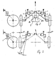
- Es zeigen :
- Fig. 1 die Ansicht der Hinterachse eines Kraftfahrzeugs nit angelenkten Niveauregelventilen;
- Fig. 2, 3 schematische Darstellungen (links Seitenansicht, rechts Draufsicht) des Fahrgestells bei
Fig. 2: Geradeausfahrt
Fig. 3: Kurvenfahrt nach links. - In der schematischen Darstellung nach den Fig. 1 bis 3 ist eine Schräglenker-Hinterachse dargestellt. Jedem Hinterrad ist ein Niveauregelventil 12 zugeordnet. Jedes Niveauregelventil ist z.B. an der Karosserie 13 befestigt. Ein geeignetes Niveauregelventil ist z.B. in der DE-PS 29 32 298 dargestellt. Jedes Niveauregelventil wird mit einer separaten Pumpe 8 L bzw. 8 R durch jeweils eine Druckleitung verbunden. Gleichwertig mit dem Einsatz von zwei separaten Pumpen ist die Verwendung einer Mehrkreispumpe. Dabei handelt es sich um eine Pumpe, die in einem Gehäuse und mit einem Antrieb zwei oder mehr Pumpelemente vorsieht, durch die die beiden Druckleitungen unabhängig voneinander mit Öl beschickt werden. Eine solche Mehrkreispumpe kann z.B. eine Radialkolbenpumpe sein, in der zwei Scheiben mit Radialzylindern und Radialkolben vorgesehen sind, die jeweils mit separaten Druckleitungen in Verbindung stehen, jedoch durch eine gemeinsame Exzenterwelle angetrieben werden. Eine solche Bauart ist z.B. in der DE-OS 39 30 248 gezeigt. Jedes der Niveauregelventile 12 L und 12 R ist durch je eine Rücklaufleitung oder eine gemeinsame Rücklaufleitung mit dem im wesentlichen drucklosen Vorratsbehälter/ Tank des Hydrauliksystems verbunden.
- Jedes Niveauregelventil besitzt eine drehbare Schieberwelle 4, durch welche die Relativbewegung zwischen Karosserie und Rad auf den Schieber des Niveauregelventils übertragen wird. Hierzu ist die Schieberwelle mit einem Stellhebel 3 fest verbunden. An das freie Ende des Stellhebels 3 ist eine Koppelstange 2 angelenkt. Das andere Ende der Koppelstange 2 ist über eine Anlenkung mit dem Schräglenker 1 der Hinterachse fest verbunden.
Die geometrische Aufhängung des Schräglenkers an der Karosserie ergibt sich aus der schematischen Ansicht nach Fig. 1. Diese Ansicht zeigt, daß die Schwenkachse des Schräglenkers nicht senkrecht zur Fahrtrichtung liegt. Im einzelnen wird hierzu auf das Buch "Fahrwerktechnik: Radaufhängungen", Reimpell, Vogel-Buchverlag 1986, S. 315 ff, verwiesen. Bei derartigen Schräglenkerachsen führt der Schräglenker bei Federbewegungen des Hinterrades eine Bewegung aus, die eine vertikale Komponente, eine horizontale Komponente in Fahrtrichtung und eine horizontale Komponente seitwärts, d.h. axial oder senkrecht zur Fahrtrichtung hat. - Erfindungsgemäß wird die Aufwärts- bzw. Abwärtsbewegung der Schräglenker zur Steuerung der Niveauregelventile herangezogen. Verschiebt sich einer der Schräglenker relativ zur Karosserie, so wird das mittels der zugeordneten Pumpe geförderte Öl über das zugeordnete Niveauregelventil in das zugeordnete Federbein gepumpt, bis die Sollage der Karosserie wieder erreicht ist, d.h. bis der konstruktiv vorgegebene Abstand der Karosserie zur Achse wieder erreicht ist. Senkt sich der Schräglenker relativ zur Karosserie, so wird Öl aus dem zugeordneten Federbein entnommen und zum Tank zurückgeführt. Durch den Umstand, daß jedem Rad eine separate Niveauregelanlage zugeordnet ist, wird die Lage am linken und am rechten Federbein auch bei unterschiedlichen Lasten genauestens erfaßt und ausgeregelt. Demgegenüber erfolgt die Niveauregelung bei einem durch nur ein Niveauregelventil ausgeregelten Fahrzeug mittels eines mittleren Regelabgriffes. Dadurch ist nach dem Stand der Technik kein seitlicher Niveauausgleich möglich. Bei der Niveauregelung durch zwei unabhängige Niveauregelkreise steht die Karosserie immer gerade. Gleichzeitig wird die Funktion des bisher üblichen Quersperrventils erfüllt. Ferner wird es durch die schräge Anlenkung der Räder möglich, nicht nur die Höhenänderung des Rades relativ zur Karosserie, sondern auch die horizontale Lageänderung zu erfassen, indem auch die seitliche Bewegung des Schräglenkers auf den Stellhebel des Niveauregelventils übertragen wird. Zu einer solchen seitlichen Bewegung kommt es insbesondere bei Kurvenfahrt. Vorraussetzung für die Erfassung dieser Seitwärtsbewegung ist, daß die Koppelstange 2, die den Schräglenker mit dem Stellhebel 3 des Niveauregelventils 12 L bzw. 12 R verbindet, nicht genau in der Bewegungsebene des Stellhebels, sondern räumlich dazu angeordnet ist. Daher erfolgt bei Lageänderung des Rades und die dadurch bewirkte Seitwärtsbewegung des Anlenkpunktes des Schräglenkers 1 auch eine Verstellung der Stellhebel 3 der Niveauregelventile, und zwar gegensätzlich.
- Die Ausnutzung der Seitwärtsbewegung der Schräglenker hat nun folgenden Vorteil: Wenn lediglich die horizontale Bewegung des Rades relativ zur Karosserie erfaßt wird, so führt dies bei Kurvenfahrt und Anwendung der Erfindung dazu, daß die durch Fliehkraft hervorgerufene seitliche Neigung der Karosserie als zusätzliche Last von dem Niveauregelven til erfaßt und durch Aufpumpen des zugeordneten Federbeins wiederausgelichen wird. Dieser Ausgleichbewegung kann durch Erfassung der Seitswärtsbewegung eine zusätzliche Steuerbewegung des Niveauregelventils i.S. einer Addition überlagert werden, was dazu führt, daß die Karosserie eine Neigung von der Außenseite zur Innenseite der Kurve erhält. Zur Niveauregelung wird also nicht nur der Höhenvektor, sondern auch der Fliehkraftvektor der Fahrwerksbewegung benutzt. Bei Geradeausfahrt wird der Fliehkraftvektor zu Null und die Niveauregelung arbeitet in der gewohnten Weise.
- Nach der Erfindung sind also an allen vier Rädern autarke, d.h. mit einer eigenen Druckölversorgung und -regelung versehene Niveauregelsysteme vorhanden. Dadurch können auch in der Ausführung nach Anspruch 1 sämtliche Wank- und Rollneigungen des Fahrzeugs erfaßt und ausgeregelt werden, da die relative Höhenlage zwischen jedem Rad und der Karosserie selbständig erfaßbar ist. Darüber hinaus ist es aber entsprechend der Lehre nach Anspruch 2 bei schräg angelenkten Achsen auch vorteilhaft, wenn - bezogen jeweils auf die Vorderachse und die Hinterachse - die Stellhebel der beiden zugeordneten Niveauregelventile durch jeweils eine Koppelstange mit einem Anlenkpunkt des Schräglenkers verbunden sind, welcher bei Auf- und Abbewegung des Rades auch eine axiale Relativbewegung relativ zu der Karosserie ausführt. Dabei ist es bei üblichen Bauarten von Niveauregelventilen, vgl. DE 29 32 298, so, daß die Anlenkpunkte an den Stellhebeln der Niveauregelventile einer Achse - in der Draufsicht und im gleichbelasteten Zustand der Räder - außerhalb der Anlenkpunkte der jeweiligen Koppelstangen an den Schräglenkern liegen. Im gleichbelasteten Zustand bilden also die Koppelstangen einer Achse die gleichlangen, gegensinnig geneigten Seiten eines regelmäßigen Trapezes, dessen kleinere, parallele Seite durch die Anlenkpunkte an dem Schräglenker und dessen größere parallele Seite durch die Anlenkpunkte an dem Stellhebel der Niveauregelventile aufgespannt wird.
- Hierdurch wird erreicht, daß die axiale Relativverschiebung in der Kurve das Niveauregelventil in demselben Sinne beeinflußt wie die in der Kurve eintretenden Änderungen der relativen Höhenlage.
-
- 1 Anlenkung an Schräglenker der Hinterachse
- 2 Koppelstange
- 3 Stellhebel des Niveauregelventils
- 4 Schieberwelle des Niveauregelventils
- 5 Schräglenker
- 6 Rad
- 7 Karosserie
- 8 Pumpe
- 9 Tank
- 10 Druckleitung
- 11 Rücklaufleitungen
- 12 Niveauregelventil
- 13 Karosserie
Claims (2)
und welche ein Niveauregelventil aufweist, das einerseits an dem Achsträger oder der Karosserie befestigt ist und das andererseits mechanisch durch einen Stellhebel mit der Hinterachse verbunden ist
und das durch Verstellung des Stellhebels mit einer Druckleitung bzw. einem im wesentlichen drucklosen Vorratsbehälter hydraulisch verbunden ist,
dadurch gekennzeichnet, daß
jedes Rad mit einem eigenen Niveauregelventil (12) zur Verstellung des ihm zugeordneten Federbeins verbunden ist, wobei jedes Niveauregelventil über eine Pumpe unabhängig von den anderen Niveauregelventilen mit Drucköl versorgt wird.
dadurch gekennzeichnet, daß
die Stellhebel (3) der Niveauregelventile (12) mit jeweils einem zur Fahrtrichtung querbeweglichen Element der Radaufhängung (Schräglenker 1) durch ein Gestänge derart verbunden sind, daß die Verringerung des Abstandes zwischen der senkrechten Längsebene der Karosserie und dem Rad zur Verstellung des zugeordneten Niveauregelventils im Sinne einer Vergrößerung des vertikalen Abstandes zwischen Rad und Karosserie führt.
Applications Claiming Priority (2)
| Application Number | Priority Date | Filing Date | Title |
|---|---|---|---|
| DE3919816 | 1989-06-16 | ||
| DE3919816 | 1989-06-16 |
Publications (3)
| Publication Number | Publication Date |
|---|---|
| EP0402820A2 true EP0402820A2 (de) | 1990-12-19 |
| EP0402820A3 EP0402820A3 (de) | 1992-03-04 |
| EP0402820B1 EP0402820B1 (de) | 1994-01-12 |
Family
ID=6382942
Family Applications (1)
| Application Number | Title | Priority Date | Filing Date |
|---|---|---|---|
| EP90110978A Expired - Lifetime EP0402820B1 (de) | 1989-06-16 | 1990-06-11 | Kraftfahrzeug mit Niveauregeleinrichtung |
Country Status (2)
| Country | Link |
|---|---|
| EP (1) | EP0402820B1 (de) |
| DE (1) | DE59004189D1 (de) |
Cited By (1)
| Publication number | Priority date | Publication date | Assignee | Title |
|---|---|---|---|---|
| EP1371508A1 (de) * | 2002-06-11 | 2003-12-17 | Continental Aktiengesellschaft | Verfahren zur Regelung einer Niveauregelanlage |
Family Cites Families (4)
| Publication number | Priority date | Publication date | Assignee | Title |
|---|---|---|---|---|
| FR1460746A (fr) * | 1965-10-07 | 1966-03-04 | Berliet Automobiles | Dispositif de commande d'un équipement de véhicule à roues en fonction des variations d'état de la suspension de ce dernier |
| DE1655963A1 (de) * | 1968-01-13 | 1971-07-01 | Boge Gmbh | Regelvorrichtung fuer hydropneumatische Federungen von Kraftfahrzeugen |
| DE3300662A1 (de) * | 1983-01-11 | 1984-07-12 | Mannesmann Rexroth GmbH, 8770 Lohr | Niveauregeleinrichtung fuer fahrzeuge |
| DE3507550A1 (de) * | 1984-07-28 | 1986-09-04 | Franz Dr.-Ing. 7530 Pforzheim Tuczek | Hydropneumatisches niveauregelndes federelement mit konstantem gasvolumen, insbesondere fuer kraftfahrzeuge |
-
1990
- 1990-06-11 DE DE90110978T patent/DE59004189D1/de not_active Expired - Fee Related
- 1990-06-11 EP EP90110978A patent/EP0402820B1/de not_active Expired - Lifetime
Cited By (1)
| Publication number | Priority date | Publication date | Assignee | Title |
|---|---|---|---|---|
| EP1371508A1 (de) * | 2002-06-11 | 2003-12-17 | Continental Aktiengesellschaft | Verfahren zur Regelung einer Niveauregelanlage |
Also Published As
| Publication number | Publication date |
|---|---|
| DE59004189D1 (de) | 1994-02-24 |
| EP0402820A3 (de) | 1992-03-04 |
| EP0402820B1 (de) | 1994-01-12 |
Similar Documents
| Publication | Publication Date | Title |
|---|---|---|
| EP1117548B1 (de) | Hydropneumatisches federungssystem | |
| DE2360149C3 (de) | Einrichtung zur Niveauregelung für Kraftfahrzeuge | |
| DD203706A5 (de) | Stabilisierungsvorrichtung fuer fahrzeugachsen | |
| DE69208723T2 (de) | System zur Regelung des Drehmomentes eines Drehstabrollstabilisators in einer unabhängigen Kraftfahrzeugaufhängung | |
| DE3881507T2 (de) | Vorrichtung für semi-aktive hydropneumatische Aufhängung und mit dieser Vorrichtung ausgestattetes Kraftfahrzeug. | |
| EP0482323A1 (de) | Federndes Abstützsystem, insbesondere für Kraftfahrzeuge | |
| DE3736284A1 (de) | Hinterradaufhaengung fuer kraftfahrzeuge | |
| DE2301686A1 (de) | Vorrichtung zum ausgleichen der achsdruecke an einem fahrgestell eines fahrzeuges | |
| DE3835225A1 (de) | Radaufhaengung | |
| DE2315238B2 (de) | Hydropneumatische Federung für Fahrzeuge mit Niveauregelung | |
| EP1557305B1 (de) | Fahrzeuganhänger | |
| DE3942654C2 (de) | Einrichtung zur Wankstabilisierung eines Fahrzeugs | |
| WO2007033718A1 (de) | Stabilisator-baugruppe für ein kraftfahrzeug | |
| DE2234410C3 (de) | Querkupplungssystem für Schienenfahrzeuge mit mehrachsigen Drehgestellen | |
| DE3936987A1 (de) | Hydropneumatisches federungssystem | |
| DE3841771A1 (de) | Rad- bzw. achsabstuetzaggregat | |
| EP0402820B1 (de) | Kraftfahrzeug mit Niveauregeleinrichtung | |
| DE4003493A1 (de) | Hydropneumatisches federungssystem | |
| DE102004022167B4 (de) | Verstellbarer Hinterachsenträger an einem Kraftfahrzeug und Verfahren zum Verstellen desselben | |
| DE4135928C2 (de) | ||
| DE953043C (de) | Vorrichtung zur Kompensierung der Neigung von Kraftfahrzeugen | |
| DE943687C (de) | Abfederung, insbesondere fuer Kraftfahrzeuge | |
| EP1364858A1 (de) | Hinter-Achse für ein Fahrzeug | |
| DE4205367A1 (de) | Achsaufhaengung fuer kraftfahrzeuge mit niveauausgleich | |
| DE102018214988A1 (de) | Höhenverstellbare Fahrzeugachse |
Legal Events
| Date | Code | Title | Description |
|---|---|---|---|
| PUAI | Public reference made under article 153(3) epc to a published international application that has entered the european phase |
Free format text: ORIGINAL CODE: 0009012 |
|
| AK | Designated contracting states |
Kind code of ref document: A2 Designated state(s): CH DE ES FR GB IT LI |
|
| PUAL | Search report despatched |
Free format text: ORIGINAL CODE: 0009013 |
|
| AK | Designated contracting states |
Kind code of ref document: A3 Designated state(s): CH DE ES FR GB IT LI |
|
| 17P | Request for examination filed |
Effective date: 19920326 |
|
| 17Q | First examination report despatched |
Effective date: 19920715 |
|
| ITF | It: translation for a ep patent filed | ||
| GRAA | (expected) grant |
Free format text: ORIGINAL CODE: 0009210 |
|
| AK | Designated contracting states |
Kind code of ref document: B1 Designated state(s): CH DE ES FR GB IT LI |
|
| PG25 | Lapsed in a contracting state [announced via postgrant information from national office to epo] |
Ref country code: ES Free format text: THE PATENT HAS BEEN ANNULLED BY A DECISION OF A NATIONAL AUTHORITY Effective date: 19940112 |
|
| ET | Fr: translation filed | ||
| REF | Corresponds to: |
Ref document number: 59004189 Country of ref document: DE Date of ref document: 19940224 |
|
| GBT | Gb: translation of ep patent filed (gb section 77(6)(a)/1977) |
Effective date: 19940311 |
|
| PGFP | Annual fee paid to national office [announced via postgrant information from national office to epo] |
Ref country code: CH Payment date: 19940624 Year of fee payment: 5 |
|
| PLBE | No opposition filed within time limit |
Free format text: ORIGINAL CODE: 0009261 |
|
| STAA | Information on the status of an ep patent application or granted ep patent |
Free format text: STATUS: NO OPPOSITION FILED WITHIN TIME LIMIT |
|
| 26N | No opposition filed | ||
| PG25 | Lapsed in a contracting state [announced via postgrant information from national office to epo] |
Ref country code: LI Effective date: 19950630 Ref country code: CH Effective date: 19950630 |
|
| REG | Reference to a national code |
Ref country code: CH Ref legal event code: PL |
|
| PGFP | Annual fee paid to national office [announced via postgrant information from national office to epo] |
Ref country code: FR Payment date: 19980508 Year of fee payment: 9 |
|
| PGFP | Annual fee paid to national office [announced via postgrant information from national office to epo] |
Ref country code: GB Payment date: 19980522 Year of fee payment: 9 |
|
| PGFP | Annual fee paid to national office [announced via postgrant information from national office to epo] |
Ref country code: DE Payment date: 19980604 Year of fee payment: 9 |
|
| PG25 | Lapsed in a contracting state [announced via postgrant information from national office to epo] |
Ref country code: GB Free format text: LAPSE BECAUSE OF NON-PAYMENT OF DUE FEES Effective date: 19990611 |
|
| PG25 | Lapsed in a contracting state [announced via postgrant information from national office to epo] |
Ref country code: FR Free format text: THE PATENT HAS BEEN ANNULLED BY A DECISION OF A NATIONAL AUTHORITY Effective date: 19990630 |
|
| GBPC | Gb: european patent ceased through non-payment of renewal fee |
Effective date: 19990611 |
|
| PG25 | Lapsed in a contracting state [announced via postgrant information from national office to epo] |
Ref country code: DE Free format text: LAPSE BECAUSE OF NON-PAYMENT OF DUE FEES Effective date: 20000503 |
|
| REG | Reference to a national code |
Ref country code: FR Ref legal event code: ST |
|
| PG25 | Lapsed in a contracting state [announced via postgrant information from national office to epo] |
Ref country code: IT Free format text: LAPSE BECAUSE OF NON-PAYMENT OF DUE FEES;WARNING: LAPSES OF ITALIAN PATENTS WITH EFFECTIVE DATE BEFORE 2007 MAY HAVE OCCURRED AT ANY TIME BEFORE 2007. THE CORRECT EFFECTIVE DATE MAY BE DIFFERENT FROM THE ONE RECORDED. Effective date: 20050611 |