EP0402623B1 - Kolben für Axialkolbenmaschinen - Google Patents
Kolben für Axialkolbenmaschinen Download PDFInfo
- Publication number
- EP0402623B1 EP0402623B1 EP90108746A EP90108746A EP0402623B1 EP 0402623 B1 EP0402623 B1 EP 0402623B1 EP 90108746 A EP90108746 A EP 90108746A EP 90108746 A EP90108746 A EP 90108746A EP 0402623 B1 EP0402623 B1 EP 0402623B1
- Authority
- EP
- European Patent Office
- Prior art keywords
- piston
- insert
- piston according
- hollow body
- wall
- Prior art date
- Legal status (The legal status is an assumption and is not a legal conclusion. Google has not performed a legal analysis and makes no representation as to the accuracy of the status listed.)
- Expired - Lifetime
Links
- 239000000463 material Substances 0.000 claims description 13
- XAGFODPZIPBFFR-UHFFFAOYSA-N aluminium Chemical compound [Al] XAGFODPZIPBFFR-UHFFFAOYSA-N 0.000 claims description 2
- 229910052782 aluminium Inorganic materials 0.000 claims description 2
- 229920003023 plastic Polymers 0.000 claims description 2
- 239000004033 plastic Substances 0.000 claims description 2
- 230000001050 lubricating effect Effects 0.000 claims 2
- 239000004411 aluminium Substances 0.000 claims 1
- 230000005484 gravity Effects 0.000 claims 1
- 238000005096 rolling process Methods 0.000 claims 1
- 239000000945 filler Substances 0.000 description 27
- 238000002788 crimping Methods 0.000 description 5
- 239000000835 fiber Substances 0.000 description 5
- 238000005461 lubrication Methods 0.000 description 4
- 238000003825 pressing Methods 0.000 description 3
- 238000007373 indentation Methods 0.000 description 2
- 238000004519 manufacturing process Methods 0.000 description 2
- 229910000838 Al alloy Inorganic materials 0.000 description 1
- 239000006096 absorbing agent Substances 0.000 description 1
- 230000001154 acute effect Effects 0.000 description 1
- 238000005520 cutting process Methods 0.000 description 1
- 238000011161 development Methods 0.000 description 1
- 230000018109 developmental process Effects 0.000 description 1
- 238000006073 displacement reaction Methods 0.000 description 1
- 238000003754 machining Methods 0.000 description 1
- 238000012805 post-processing Methods 0.000 description 1
- 230000000717 retained effect Effects 0.000 description 1
- 230000035939 shock Effects 0.000 description 1
- 239000011343 solid material Substances 0.000 description 1
Images

Classifications
-
- F—MECHANICAL ENGINEERING; LIGHTING; HEATING; WEAPONS; BLASTING
- F04—POSITIVE - DISPLACEMENT MACHINES FOR LIQUIDS; PUMPS FOR LIQUIDS OR ELASTIC FLUIDS
- F04B—POSITIVE-DISPLACEMENT MACHINES FOR LIQUIDS; PUMPS
- F04B1/00—Multi-cylinder machines or pumps characterised by number or arrangement of cylinders
- F04B1/12—Multi-cylinder machines or pumps characterised by number or arrangement of cylinders having cylinder axes coaxial with, or parallel or inclined to, main shaft axis
- F04B1/122—Details or component parts, e.g. valves, sealings or lubrication means
- F04B1/124—Pistons
-
- F—MECHANICAL ENGINEERING; LIGHTING; HEATING; WEAPONS; BLASTING
- F16—ENGINEERING ELEMENTS AND UNITS; GENERAL MEASURES FOR PRODUCING AND MAINTAINING EFFECTIVE FUNCTIONING OF MACHINES OR INSTALLATIONS; THERMAL INSULATION IN GENERAL
- F16B—DEVICES FOR FASTENING OR SECURING CONSTRUCTIONAL ELEMENTS OR MACHINE PARTS TOGETHER, e.g. NAILS, BOLTS, CIRCLIPS, CLAMPS, CLIPS OR WEDGES; JOINTS OR JOINTING
- F16B17/00—Connecting constructional elements or machine parts by a part of or on one member entering a hole in the other and involving plastic deformation
- F16B17/004—Connecting constructional elements or machine parts by a part of or on one member entering a hole in the other and involving plastic deformation of rods or tubes mutually
-
- Y—GENERAL TAGGING OF NEW TECHNOLOGICAL DEVELOPMENTS; GENERAL TAGGING OF CROSS-SECTIONAL TECHNOLOGIES SPANNING OVER SEVERAL SECTIONS OF THE IPC; TECHNICAL SUBJECTS COVERED BY FORMER USPC CROSS-REFERENCE ART COLLECTIONS [XRACs] AND DIGESTS
- Y10—TECHNICAL SUBJECTS COVERED BY FORMER USPC
- Y10T—TECHNICAL SUBJECTS COVERED BY FORMER US CLASSIFICATION
- Y10T29/00—Metal working
- Y10T29/49—Method of mechanical manufacture
- Y10T29/49229—Prime mover or fluid pump making
- Y10T29/49236—Fluid pump or compressor making
-
- Y—GENERAL TAGGING OF NEW TECHNOLOGICAL DEVELOPMENTS; GENERAL TAGGING OF CROSS-SECTIONAL TECHNOLOGIES SPANNING OVER SEVERAL SECTIONS OF THE IPC; TECHNICAL SUBJECTS COVERED BY FORMER USPC CROSS-REFERENCE ART COLLECTIONS [XRACs] AND DIGESTS
- Y10—TECHNICAL SUBJECTS COVERED BY FORMER USPC
- Y10T—TECHNICAL SUBJECTS COVERED BY FORMER US CLASSIFICATION
- Y10T29/00—Metal working
- Y10T29/49—Method of mechanical manufacture
- Y10T29/49229—Prime mover or fluid pump making
- Y10T29/49249—Piston making
- Y10T29/49252—Multi-element piston making
Definitions
- the invention relates to a piston according to the preamble of claim 1.
- Such a piston generally referred to as a light piston, is described and illustrated in DE-GM 71 08 800.
- the filler is formed by crimping a portion of the wall of the hollow body projecting beyond the free end of the filler against the end face of the filler.
- the strength of the axial holding of the filler between the bottom of the cavity and the crimp achieved in this way is insufficient because, on the one hand, the crimp springs back somewhat after the crimping, and on the other hand the crimping due to the presence of a relatively long curvature during crimping Comparatively long lever arm equals, the axial clamping force is relatively low.
- the desired goal of biasing the filler against the bottom of the cavity with a certain amount of tension exerted by the crimp cannot be achieved.
- EP-A-0259010 describes a piston for a shock absorber, the hollow piston shaft of which consists of two sleeve-shaped longitudinal sections which are inserted into one another in the manner of a sleeve and by means of a curl which is introduced into the circumference of the outer longitudinal section and extends into the inner longitudinal section extends, are interconnected.
- a filler is not provided in this known piston.
- this known embodiment adheres to the features described above with respect to DE-C 38 04 424.
- the invention has for its object to design a piston of the type mentioned in such a way that, while ensuring simple and inexpensive manufacture, a stable mounting of the filling piece and a stable design of the shaft of the piston are achieved.
- the envelope in contrast to the known flanging, has a concavely rounded wall profile, which means that the envelope has a relatively high degree of inherent stability due to self-support, so that it is able to exert a comparatively large clamping force that is effective against the end face of the filling piece and thus the filling piece without the risk of axial loosening in the cavity of the hollow body. Since in the embodiment according to the invention the constriction of the cross-section of the piston specified by the envelope according to the invention is located at the free end of the piston skirt, the risk of stress cracks or rupture of the piston is excluded.
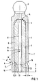
- the pistons generally designated 1 in the figures each consist of a piston skirt 2 and a spherical piston head 3.
- a blind hole-shaped cavity 4 extends from its free end, the bottom of which is labeled 5.
- the piston skirt 2 is thus a hollow body.
- a filler 6 is used in the cavity 4, which largely fills the cavity 4 according to FIG. 1, rests against the base 5 of the cavity 4 and extends essentially to the free end of the piston 1, designated 7.
- the filler 6 consists of a material with a material that is different from the material of the hollow body 2 lower specific weight, whereby the weight or the mass of the piston 1 is substantially reduced. 1, the filler 6 consists of an aluminum alloy.
- an envelope designated 8 is provided, which is formed by a curl 9 of the wall 11 of the piston skirt 2.
- the envelope 8 is located at the free end 7 of the finished piston 1, and it can extend into a recess or annular groove 12 in the filler 6, or it can also be rolled or rolled into the surface of the filler 6 with deformation into an annular groove 12 be. In both cases, a rounded curl 9 results in an increase in the curvature radius R of the annular groove 12 in comparison with the radius of curvature r of the curl 9 of the wall thickness d of the piston skirt 2.
- annular groove 12 is provided from the outset, it is advantageous to slightly offset the annular groove 12 with respect to the curl 9 towards the free end 7, so that the curl 9 presses against the flank 13 of the annular groove 12 facing away from the free end 7 and thereby Filler piece 6, if necessary, also presses with deformation of the flank 13 with its inner end face 14 against the base 5 of the cavity 4 and thus braces it.
- the piston 1 After attaching the curl 9, which is located at a short distance a from the free end 7.1 of the prefabricated piston 1, the piston 1 is cut to length in the area of the curl 9 so that a Part 16 of the curl 9 facing away from the free end 7 remains on the piston 1 and takes over the holding or securing function for the filler 6.
- the parting plane E or the final free end 7 of the piston 1 preferably extends approximately in the half of the curl 9 facing away from the piston head 3. It is advantageous to design the end face at the free end 7 to be rounded or frustoconical, the conical surface with the Longitudinal axis 18 of the piston 1 encloses an acute angle w and preferably runs out at the inner corner 19 of the curl 9 or at a small, outward distance c therefrom on the circumference of the piston shaft 2.
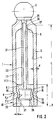
- the piston 1 has a coaxially continuous lubrication bore 21, which thus also extends in the filler 6.
- a closure or insert piece 6.1 is used, which has at the free end 7 of the piston a head 22 filling the cavity 4, from which a cylindrical neck 23, which is significantly tapered in diameter, extends axially inwards which, with its inner end, engages in the lubrication bore section 25, which extends in the piston neck and in the piston head 3, with a tapered section 26, a shoulder 27 formed by the taper bearing against the base 5 of the cavity 2 in the region of the free end of the neck 23, whereby the insert 6.1 is secured against displacement inwards.
- the length l of the head 22 is only a fraction of the length L of the piston skirt 2.
- the head 22 of the insert 6.1 in the area of the curl 9 has a bore extension 28, which is surrounded by a hollow cylindrical wall 29 with the thickness e and can be bent in due to its relatively small thickness e.
- this wall 29 is bent in, as shown in FIG. 2, and as a result a rear grip is formed for the envelope 8 formed by the curl 9.
- the bore extension 28 is arranged in the parting plane E passing through the curl 9, a wall section 31 being thickened in a step-like manner with respect to the wall 29 being present at the free end of the piston skirt extension 10.
- the wall 11 of the piston skirt 2 or the material fibers shown and designated 32 are concave in the area of the curl 9, wherein when curling in the direction of the curl force indicated by arrow 33, divergent force components 34 result, which Press or squeeze material sideways. Due to the concave shape and mutual support, the flanks of the curl 9 are largely prevented from springing back.
- the material fibers 43 are cut transversely through the end face of the piston 1 or separating surface, so that the pretension is retained.
- the piston 1 is roughly manufactured as follows. Manufacture of the piston skirt 2 with the piston head 3 including the resulting lubrication bore section and the filler 6 or insert 6.1, likewise with the associated lubrication bore section. Inserting or pressing the filler 6 or insert 6.1 into the cavity 4 of the piston skirt 2. Roll up the curl 9. Cutting the piston 1 to length in the parting plane E. If necessary. Attach the frustoconical face. Revise (turning, grinding) the outer surface of the piston skirt 2 and, if necessary, the end face at its free end and the piston head 2.
- the filler piece 6.1 has a similar one due to the existing recess or because of its brevity Filler made of solid material reduced weight. Therefore, such a recessed filler 6.1 does not need to consist of a light material such as aluminum or plastic, but it can also be of the same material as the piston skirt 2.
Landscapes
- Engineering & Computer Science (AREA)
- General Engineering & Computer Science (AREA)
- Mechanical Engineering (AREA)
- Pistons, Piston Rings, And Cylinders (AREA)
Applications Claiming Priority (2)
| Application Number | Priority Date | Filing Date | Title |
|---|---|---|---|
| DE3919329 | 1989-06-13 | ||
| DE3919329A DE3919329C1 (ja) | 1989-06-13 | 1989-06-13 |
Publications (2)
| Publication Number | Publication Date |
|---|---|
| EP0402623A1 EP0402623A1 (de) | 1990-12-19 |
| EP0402623B1 true EP0402623B1 (de) | 1993-12-15 |
Family
ID=6382684
Family Applications (1)
| Application Number | Title | Priority Date | Filing Date |
|---|---|---|---|
| EP90108746A Expired - Lifetime EP0402623B1 (de) | 1989-06-13 | 1990-05-09 | Kolben für Axialkolbenmaschinen |
Country Status (3)
| Country | Link |
|---|---|
| US (1) | US5076148A (ja) |
| EP (1) | EP0402623B1 (ja) |
| DE (2) | DE3919329C1 (ja) |
Families Citing this family (18)
| Publication number | Priority date | Publication date | Assignee | Title |
|---|---|---|---|---|
| US5265331A (en) * | 1992-01-16 | 1993-11-30 | Caterpillar Inc. | Method of manufacturing a piston for an axial piston fluid translating device |
| US5642654A (en) * | 1994-09-01 | 1997-07-01 | Sundstrand Corporation | Piston and method of manufacturing the same |
| US6016739A (en) * | 1995-06-07 | 2000-01-25 | Sundstrand Corporation | Piston and method for reducing wear |
| DE19706075C2 (de) * | 1997-02-17 | 2001-05-17 | Brueninghaus Hydromatik Gmbh | Kolben für eine hydrostatische Maschine |
| US6250206B1 (en) | 1999-02-10 | 2001-06-26 | Sauer-Danfoss Inc. | Hydraulic piston filling |
| DE19938046A1 (de) * | 1999-08-12 | 2001-03-08 | Brueninghaus Hydromatik Gmbh | Hohlkolben für eine Kolbenmaschine und Verfahren zum Herstellen eines Hohlkolbens |
| US6318242B1 (en) | 1999-10-26 | 2001-11-20 | Sauer-Danfoss Inc. | Filled hydraulic piston and method of making the same |
| US6293185B1 (en) * | 2000-02-28 | 2001-09-25 | Sauer-Danfoss Inc. | Piston for a hydrostatic cylinder block |
| US6431051B1 (en) | 2000-03-31 | 2002-08-13 | Sauer-Danfoss Inc. | Closed cavity hydraulic piston and method of making the same |
| US6274083B1 (en) | 2000-06-14 | 2001-08-14 | Sauer-Danfoss Inc. | Method of producing a hollow piston for a hydrostatic power unit |
| US6338293B1 (en) | 2000-06-30 | 2002-01-15 | Sauer-Danfoss Inc. | Reduced oil volume piston assembly for a hydrostatic unit |
| US6314864B1 (en) * | 2000-07-20 | 2001-11-13 | Sauer-Danfoss Inc. | Closed cavity piston for hydrostatic units |
| US6588321B1 (en) | 2000-11-27 | 2003-07-08 | Sauer-Danfoss Inc. | Closed cavity piston and method of making the same |
| DE10206729B4 (de) * | 2002-02-18 | 2004-02-05 | Brueninghaus Hydromatik Gmbh | Hohlkolben mit Hohlkugelfüllung |
| DE10341791B4 (de) | 2003-09-10 | 2005-09-29 | Brueninghaus Hydromatik Gmbh | Hohlkolben für eine Kolbenmaschine und Verfahren zum Herstellen eines Hohlkolbens |
| DE102009056903A1 (de) | 2009-12-03 | 2011-06-09 | Danfoss A/S | Hydraulische Kolbenmaschine, insbesondere wasserhydraulische Maschine |
| DE102010032236A1 (de) | 2010-07-26 | 2012-01-26 | Robert Bosch Gmbh | Verfahren zur Herstellung eines Hohlkolbens und entsprechender Hohlkolben |
| JP6071132B2 (ja) * | 2013-03-28 | 2017-02-01 | Kyb株式会社 | 接合体 |
Family Cites Families (8)
| Publication number | Priority date | Publication date | Assignee | Title |
|---|---|---|---|---|
| DE7108800U (de) * | 1971-07-08 | Gebr Claas | Hohlkolben fur hydraulische Axial oder Radialkolbenaggregate | |
| US3068563A (en) * | 1958-11-05 | 1962-12-18 | Westinghouse Electric Corp | Metal joining method |
| SU412813A1 (ru) * | 1972-02-11 | 1982-06-15 | Всесоюзный научно-исследовательский и проектно-конструкторский институт промышленных гидроприводов и гидроавтоматики | Составной поршень |
| FR2183347A5 (ja) * | 1972-05-03 | 1973-12-14 | Ffsa | |
| DE3204264A1 (de) * | 1982-02-08 | 1983-08-18 | Char'kovskij politechničeskij institut imeni V.I. Lenina, Char'kov | Mehrteiliger kolben fuer hydraulische verdraengungsmaschinen und verfahren zu dessen herstellung |
| DE3239175C1 (de) * | 1982-10-22 | 1984-03-01 | Hydromatik GmbH, 7915 Elchingen | Lagerung des triebflansches einer axialkolbenmaschine in schraegachsen-bauart. |
| DE3763329D1 (de) * | 1986-09-02 | 1990-07-26 | Gen Motors Corp | Verfahren zur herstellung eines einheitsmoduls mit kolben und kolbenstange. |
| DE3804424C1 (en) * | 1988-02-12 | 1989-08-24 | Hydromatik Gmbh, 7915 Elchingen, De | Piston for axial-piston machines |
-
1989
- 1989-06-13 DE DE3919329A patent/DE3919329C1/de not_active Expired - Fee Related
-
1990
- 1990-05-09 DE DE90108746T patent/DE59003844D1/de not_active Expired - Fee Related
- 1990-05-09 EP EP90108746A patent/EP0402623B1/de not_active Expired - Lifetime
- 1990-06-13 US US07/537,472 patent/US5076148A/en not_active Expired - Lifetime
Also Published As
| Publication number | Publication date |
|---|---|
| EP0402623A1 (de) | 1990-12-19 |
| US5076148A (en) | 1991-12-31 |
| DE59003844D1 (de) | 1994-01-27 |
| DE3919329C1 (ja) | 1990-12-06 |
Similar Documents
| Publication | Publication Date | Title |
|---|---|---|
| EP0402623B1 (de) | Kolben für Axialkolbenmaschinen | |
| EP0667936B2 (de) | Verfahren zur herstellung eines auspress- und drehfesten verbundteils durch einpressen eines einpressteils in ein blechteil sowie dafür geeignete einpressteile | |
| DE3804424C1 (en) | Piston for axial-piston machines | |
| EP0758039B1 (de) | Ankerschiene für die Bautechnik | |
| DE602004012378T2 (de) | Speiche für Fahrradrad und Fahrradrad eine solche Speiche enthaltend sowie Herstellverfahren für eine solche Speiche | |
| DE1427377C3 (de) | Verfahren zum Herstellen eines Befestigungselementes | |
| EP1198325B1 (de) | Hohlkolben für eine kolbenmaschine und verfahren zum herstellen eines hohlkolbens | |
| EP1010901A1 (de) | Metallischer Einsatz | |
| DE19710847C2 (de) | Zusammengesetzte Steuerwelle und Verfahren für deren Herstellung | |
| DE1116482B (de) | Niet zum Blindnieten | |
| EP0483660B1 (de) | Passniet für hochbeanspruchte Nietverbindungen | |
| EP1414613B1 (de) | Hydraulikkolben aus walzblech und verfahren zu dessen herstellung | |
| DE10251784B4 (de) | Schnapp-Kugelzapfen | |
| DE3519015C2 (de) | Ventilstößel für Verbrennungskraftmaschinen | |
| DE19741491C1 (de) | Kolbenbolzen und Verfahren zur Herstellung eines Kolbenbolzens | |
| DE3900186A1 (de) | Verfahren zur herstellung eines kolbenbolzens | |
| DE3733910C2 (ja) | ||
| DE102022001227B3 (de) | Kugelgelenk und Verfahren für seine Montage | |
| DE102008060841A1 (de) | Hohlkolben für eine Kolbenmaschine | |
| DE102016207673B4 (de) | Verfahren zum Herstellen einer Bauteilverbindung sowie Bauteilverbindung | |
| DE2724800A1 (de) | Verfahren zum herstellen einer naben-wellen-verbindung, insbesondere fuer ventilatorraeder, und durch das verfahren hergestellte verbindung | |
| CH675457A5 (en) | Hollow cylindrical hub with shaft fastener(s) - has axial, arcuated slot, dividing cylinder into outer, thicker section and inner thinner section | |
| DE3916174A1 (de) | Elastisches verbindungselement | |
| DE2206134C3 (de) | Bewegbares Gelenk | |
| DE102021103979A1 (de) | Nietelement und Zusammenbauteil bestehend aus dem Nietelement und einem Bauteil |
Legal Events
| Date | Code | Title | Description |
|---|---|---|---|
| PUAI | Public reference made under article 153(3) epc to a published international application that has entered the european phase |
Free format text: ORIGINAL CODE: 0009012 |
|
| AK | Designated contracting states |
Kind code of ref document: A1 Designated state(s): DE FR GB IT SE |
|
| 17P | Request for examination filed |
Effective date: 19901114 |
|
| 17Q | First examination report despatched |
Effective date: 19920416 |
|
| GRAA | (expected) grant |
Free format text: ORIGINAL CODE: 0009210 |
|
| AK | Designated contracting states |
Kind code of ref document: B1 Designated state(s): DE FR GB IT SE |
|
| ITF | It: translation for a ep patent filed |
Owner name: JACOBACCI CASETTA & PERANI S.P.A. |
|
| REF | Corresponds to: |
Ref document number: 59003844 Country of ref document: DE Date of ref document: 19940127 |
|
| ET | Fr: translation filed | ||
| GBT | Gb: translation of ep patent filed (gb section 77(6)(a)/1977) |
Effective date: 19940321 |
|
| PLBE | No opposition filed within time limit |
Free format text: ORIGINAL CODE: 0009261 |
|
| STAA | Information on the status of an ep patent application or granted ep patent |
Free format text: STATUS: NO OPPOSITION FILED WITHIN TIME LIMIT |
|
| 26N | No opposition filed | ||
| EAL | Se: european patent in force in sweden |
Ref document number: 90108746.0 |
|
| REG | Reference to a national code |
Ref country code: GB Ref legal event code: IF02 |
|
| PGFP | Annual fee paid to national office [announced via postgrant information from national office to epo] |
Ref country code: SE Payment date: 20070515 Year of fee payment: 18 |
|
| PGFP | Annual fee paid to national office [announced via postgrant information from national office to epo] |
Ref country code: DE Payment date: 20070522 Year of fee payment: 18 |
|
| PGFP | Annual fee paid to national office [announced via postgrant information from national office to epo] |
Ref country code: GB Payment date: 20070522 Year of fee payment: 18 |
|
| PGFP | Annual fee paid to national office [announced via postgrant information from national office to epo] |
Ref country code: IT Payment date: 20070525 Year of fee payment: 18 |
|
| GBPC | Gb: european patent ceased through non-payment of renewal fee |
Effective date: 20080509 |
|
| PG25 | Lapsed in a contracting state [announced via postgrant information from national office to epo] |
Ref country code: DE Free format text: LAPSE BECAUSE OF NON-PAYMENT OF DUE FEES Effective date: 20081202 |
|
| PG25 | Lapsed in a contracting state [announced via postgrant information from national office to epo] |
Ref country code: GB Free format text: LAPSE BECAUSE OF NON-PAYMENT OF DUE FEES Effective date: 20080509 |
|
| PG25 | Lapsed in a contracting state [announced via postgrant information from national office to epo] |
Ref country code: IT Free format text: LAPSE BECAUSE OF NON-PAYMENT OF DUE FEES Effective date: 20080509 |
|
| REG | Reference to a national code |
Ref country code: FR Ref legal event code: ST Effective date: 20100129 |
|
| PG25 | Lapsed in a contracting state [announced via postgrant information from national office to epo] |
Ref country code: FR Free format text: LAPSE BECAUSE OF NON-PAYMENT OF DUE FEES Effective date: 20090602 |
|
| PGFP | Annual fee paid to national office [announced via postgrant information from national office to epo] |
Ref country code: FR Payment date: 20080425 Year of fee payment: 19 |
|
| PG25 | Lapsed in a contracting state [announced via postgrant information from national office to epo] |
Ref country code: SE Free format text: LAPSE BECAUSE OF NON-PAYMENT OF DUE FEES Effective date: 20080510 |