EP0402449B1 - Apparat und verfahren zur zucht von tierzellen - Google Patents
Apparat und verfahren zur zucht von tierzellen Download PDFInfo
- Publication number
- EP0402449B1 EP0402449B1 EP90901239A EP90901239A EP0402449B1 EP 0402449 B1 EP0402449 B1 EP 0402449B1 EP 90901239 A EP90901239 A EP 90901239A EP 90901239 A EP90901239 A EP 90901239A EP 0402449 B1 EP0402449 B1 EP 0402449B1
- Authority
- EP
- European Patent Office
- Prior art keywords
- culture
- housing
- subunit
- receptacle
- spent
- Prior art date
- Legal status (The legal status is an assumption and is not a legal conclusion. Google has not performed a legal analysis and makes no representation as to the accuracy of the status listed.)
- Expired - Lifetime
Links
Images


Classifications
-
- C—CHEMISTRY; METALLURGY
- C12—BIOCHEMISTRY; BEER; SPIRITS; WINE; VINEGAR; MICROBIOLOGY; ENZYMOLOGY; MUTATION OR GENETIC ENGINEERING
- C12M—APPARATUS FOR ENZYMOLOGY OR MICROBIOLOGY; APPARATUS FOR CULTURING MICROORGANISMS FOR PRODUCING BIOMASS, FOR GROWING CELLS OR FOR OBTAINING FERMENTATION OR METABOLIC PRODUCTS, i.e. BIOREACTORS OR FERMENTERS
- C12M29/00—Means for introduction, extraction or recirculation of materials, e.g. pumps
- C12M29/04—Filters; Permeable or porous membranes or plates, e.g. dialysis
-
- C—CHEMISTRY; METALLURGY
- C12—BIOCHEMISTRY; BEER; SPIRITS; WINE; VINEGAR; MICROBIOLOGY; ENZYMOLOGY; MUTATION OR GENETIC ENGINEERING
- C12M—APPARATUS FOR ENZYMOLOGY OR MICROBIOLOGY; APPARATUS FOR CULTURING MICROORGANISMS FOR PRODUCING BIOMASS, FOR GROWING CELLS OR FOR OBTAINING FERMENTATION OR METABOLIC PRODUCTS, i.e. BIOREACTORS OR FERMENTERS
- C12M23/00—Constructional details, e.g. recesses, hinges
- C12M23/34—Internal compartments or partitions
-
- C—CHEMISTRY; METALLURGY
- C12—BIOCHEMISTRY; BEER; SPIRITS; WINE; VINEGAR; MICROBIOLOGY; ENZYMOLOGY; MUTATION OR GENETIC ENGINEERING
- C12M—APPARATUS FOR ENZYMOLOGY OR MICROBIOLOGY; APPARATUS FOR CULTURING MICROORGANISMS FOR PRODUCING BIOMASS, FOR GROWING CELLS OR FOR OBTAINING FERMENTATION OR METABOLIC PRODUCTS, i.e. BIOREACTORS OR FERMENTERS
- C12M25/00—Means for supporting, enclosing or fixing the microorganisms, e.g. immunocoatings
- C12M25/16—Particles; Beads; Granular material; Encapsulation
Definitions
- the present invention relates to the propagation of animal cells for the purpose of recovering cell-secreted products of interest therefrom, and more particularly to an apparatus and process for the large-scale propagation of animal cells for such purpose.
- animal cells particularly human cells
- secrete in vivo a wide variety of protein products which, directly or indirectly, are responsible for effecting particular functions or controlling or regulating particular functions in the species, including products such as hormones, enzymes, antibodies, clotting agents, and the like.
- products such as hormones, enzymes, antibodies, clotting agents, and the like.
- naturally-secreted products if capable of being isolated and recovered from an animal, offer enormous potential in the diagnostic and therapeutic fields.
- each such unit must be separately seeded, separately fed and gassed, separately observed and maintained, and separately processed to collect therefrom culture fluid containing secreted cell product, all of which adds enormously to the labor and equipment required and, hence, to the production cost (e.g., per gram) of the product of interest.
- a far more economical route to large-scale production of secreted cell products via animal cell culture is simply to increase (i.e., scale-up) the capacity of a proven small-scale culture device such that it can accommodate many more cells and generate correspondingly larger quantities of product.
- Scale-up of these small-scale culture units has generally been quite unsuccessful, however, i.e., their capacity cannot be increased cost effectively while still maintaining the process and product-producing efficiencies demonstrated in the small-scale units.
- this inability is due to the difficulty of achieving any reasonable degree of homogeneity in the in vitro environment per se , and the further inability to expose even a majority of cells in high density clusters to the requisite nutrition and gas components of the culture medium.
- stirred tank reactors For large-scale culturing of anchorage-dependent cells, the stirred tank reactor and fluidized bed reactor can be employed by propagating the cells on or within solid carriers which, in turn, are maintained in suspension in the in vitro environment.
- these carrier systems are not presently capable of supporting the growth of all anchorage-dependent cell lines of interest and, in scaled-up systems, often-times exhibit reduced levels of product secretion as compared to that found in small, laboratory-scale units.
- glass bead packed bed reactor units can easily be scaled-up in size per se (i.e., made larger), but only at a significant loss of process and product-production efficiency and at a significant loss in the ability to easily translate to large scale, if at all, the nutrition and other growth and product-secretion parameters determined to be optimum for a particular cell line in small-scale laboratory tests. Without this latter ability, each scale-up ends up requiring a comprehensive development program to reestablish operable and/or optimum growth conditions, nutrient requirements and the like, adding enormously to the costs of production when just the opposite is desired.
- the primary object of the present invention is to provide an in vitro cell culture system for animal cells, based upon the principles of glass bead packed bed culture systems, which can be readily, economically and predictably scaled-up to accommodate and effect large-scale production of secreted cell products of interest.
- a culture system is provided based upon a vertically stacked arrangement, within a common housing, of two or more culture subunits each containing a packed bed of carrier particles (e.g., glass beads) upon which growth of anchorage-dependent animal cells can occur or in the void space of which growth of non-anchorage-dependent animal cells can occur.
- a single feed of culture medium is provided to the housed arrangement and therein serves as a separate feed of culture medium to each culture subunit.
- spent culture fluid having passed through the packed bed and thus having its nutrients depleted by the growing cells affixed to or entrapped between the bed particles and having collected from the cells secreted cell products, including secreted cell proteins of interest, exits from each separate culture subunit and is communicated to a common spent culture fluid conduit where it commingles with spent culture fluid from all other culture subunits within the housing for removal from the housed arrangement and further processing to recover secreted cell proteins of interest.
- each culture subunit is sized so as to present a depth of carrier particle bed which is substantially the same as that commonly employed in conducting preliminary experiments on growth conditions, flow characteristics, nutrient and gassing requirements, product secretion characteristics and rates, and other like parameters, for particular cell lines.
- the culture subunits are simply multiplied in number and arranged within the common housing provided by the invention and/or increased in volume, without substantial change in the depth of the packed bed. Since each culture subunit operates as an independent culture device, the majority of operating characteristics (particularly flow characteristics) and operating results established for a particular cell line and a particular bed of carrier particles are directly, and predictably, applicable to the scaled-up system.
- the culture medium feed and product (spent culture fluid) collection system is arranged to be common for all culture subunits so that, in terms of medium processing, gassing, product collection, maintenance, sampling and the like, the multi-subunit reactor system essentially operates as a single culture unit in gross.
- the culture system of the present invention enables both scale-up and scale-down of a culture operation in a predictable and economic manner, generally involving simply the addition or subtraction of discrete culture subunits within the housed system and/or increase or decrease in the volume of each culture subunit while generally maintaining a packed bed height substantially the same as that employed in a culture system (be it a single or multi-subunit one) of smaller or larger capacity for which operating parameters and characteristics have already been established.
- each subunit can be described as a basket-like enclosure or receptacle which is either a separable enclosure per se or is formed at least in part by portions of the housing.
- Each basket-like enclosure (culture subunit) has a base and a surrounding, upstanding side wall and, positioned above the plane of the base a perforate or porous plate upon which the packed bed of carrier particles resides, and through which spent culture fluid, having passed through the bed, can flow into a liquid collection space defined by the area between the base and the perforate plate.
- each culture subunit is in liquid communication with a common conduit, generally defined by a hollow stem in association with one or more of the subunits, such that spent culture fluid from each unit is commingled for egress from the housed arrangement and further processing.
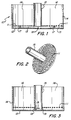
- FIG. 1 is a cross-sectional view of a single cylindrical culture subunit which can be added to a housed culture arrangement for scale-up thereof.
- FIG. 2 is a perspective view of a combined stem and perforate plate element utilized in forming a culture subunit according to the invention.
- FIGS. 3 and 4 are cross-sectional views of basket-like culture subunits such as shown in FIG. 1 illustrating different arrangements of the stem element.
- FIG. 5 is a cross-sectional view of two culture subunit enclosures arranged along a common stem.
- FIG. 6 is a cross-sectional view of a single basket-like subunit such as shown in FIG. 1 within a housing.
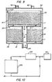
- FIG. 7 is a cross-sectional view of a multi-stage culture system according to the invention consisting of four culture subunits within a common housing.
- FIG. 8 is a cross-sectional view of the apparatus shown in FIG. 7 which illustrates the flow of culture medium and spent culture fluid throughout the system.
- FIG. 9 is a cross-sectional view of a two-stage culture system according to the invention.
- FIG. 10 is a schematic of a culture process employing the housed culture system of the invention.
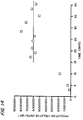
- FIGS. 11, 12, 13 and 14 are graphical depictions of the results of scale-up experiments using the reactor system of the invention.
- this first integral subunit so described need not necessarily be present as such (i.e., as an integral unit in the form shown) in order to provide a highly useful, scaleable system according to the invention (see, e.g., FIG. 9), although it is employed in preferred embodiments of the invention containing three or more subunits (see, e.g., FIGS. 7 and 8). It is, however, first presented as a means for illustrating various details not only of this subunit but also of subunits which may differ in other details.
- a basket-like element or receptacle 10 (shown in cross-section in FIG. 1) adapted to receive and retain a plurality of carrier particles (generally glass beads) upon which growth of anchorage-dependent animal cells can occur or between the voids of which growth of non-anchorage-dependent animal cells can occur.
- the cylindrical basket element is comprised of a base section 12 and upstanding surrounding side wall 14 extending from the periphery of the base section which serves to define an enclosed space 16 for receiving glass beads.
- the base section 12 and side wall 14 are made of solid and liquid impervious material compatible with animal cell culture, such as plastic or stainless steel, and are either integral surfaces or affixed in a way so as to provide a liquid-tight enclosure.
- the basket element Arranged in circular base section 12, generally at the center thereof, is a liquid outlet opening 18 through which spent culture fluid may flow out of the basket enclosure.
- the basket element further contains a generally rigid perforate or porous plate element 11, generally in the nature of a screen or rigid mesh, of substantially the same planar area and configuration of base section 12 (i.e., extending out to side wall 14 so as to be very close thereto or, preferably, in contact therewith) and disposed a small distance above base section 12 so as to define a culture fluid collection space 13 therebetween which is in fluid communication with outlet 18 in base section 12.
- the degree of and size of perforation or porosity of perforate base plate 11 is chosen so as to prevent passage therethrough of glass beads which rest on and lie above it, while permitting spent culture fluid to pass through it to collection space 13.
- Basket element 10 further comprises a hollow stem 15 made of solid and liquid-impervious material which extends from a position over outlet 18 and vertically into the basket interior.
- Stem 15 is open at its terminal portions so as to enable it to serve as a conduit through which spent culture fluid may flow, e.g., as part of a conduit system for receiving spent culture fluid from the collection spaces of other culture subunits arranged within the common housing.
- the portion comprised of base section 12 and side wall enclosure 14 is provided as a single receptacle element, having liquid outlet 18 arranged in base section 12.
- a second insert element is provided comprised of hollow stem 15 (open at its terminal portions) and, affixed thereto at or near its lower end, porous base element 11 (see FIG. 2).
- the underside of porous base element 11 (or alternatively, the upper side of base section 12) is provided with stand-off or spacer elements (e.g., elements 17 in FIG. 1) such that, when the portion shown in FIG.
- the porous base element 11 occupies a horizontal plane which is a small predetermined distance above the plane of base section 12, thereby defining a collection space 13. This same effect can be accomplished with a number of fingers emanating from about the inner periphery of side wall 14 and upon which the stem/porous plate element can be rested and supported a small predetermined distance above the plane of base section 12.
- stem 15 it is possible to arrange stem 15 to be integral with base section 12, i.e., a bottom portion of stem 15 can be affixed at or within liquid outlet opening 18 of base section 12, as shown in FIGS. 3 and 4.
- stem 15, in the area which lies within collection space 13, is provided about its periphery with a number of discontinuous fluid openings 19 so as to enable spent culture fluid in collection space 13 to enter the hollow interior of stem 15.
- porous base element 11 can be either permanently affixed, a short predetermined distance above base section 12, along the inner periphery of side wall 14, or alternatively, can simply be adapted to fit over stem 15 and, by virtue of stand-offs on the porous base element or base section 12, or protruding fingers from side wall 14, be arranged to reside a small distance above base section 12 for purposes of defining collection space 13.
- stem 15 can be in the form of an elongate stem, not affixed to either base section 12 or porous base element 11 but supported elsewhere, along which are provided a number of discontinuous stops or a continuous collar (e.g., collar 25) upon which the base section 12 of a basket can rest so as to support the basket at a predetermined location on the stem.
- the stem 15, in the area or areas which will lie within a collection space or spaces, will be provided about its periphery with a number of discontinuous fluid openings 19 to permit spent culture fluid in the collection space 13 to enter the hollow interior of the stem.
- basket subunit 10 is arranged within a housing 20 (see FIG. 6) which is of the same general geometric shape as the basket subunit, e.g., a cylindrical housing for cylindrical basket elements.
- the cross-sectional dimensions of the housing 20 are such that, when basket subunit 10 is arranged therein, a small predetermined annular culture medium feed space 21 exists between the inner peripheral surface of the housing 20 and the outer peripheral surface of the basket subunit 10.
- the housing 20 is made of solid and fluid impervious material, such as plastic (e.g., polycarbonate) or stainless steel.
- a basket subunit For arranging a basket subunit to occupy a fixed vertical position within housing 20, use can be made, for example, of stops or a collar along a unitary elongated stem 15, as shown in FIG. 5, or, in the preferred embodiment as described hereinafter, by stacking upon stems of predetermined heights.
- FIG. 7 illustrates a culture system according to a preferred embodiment of the invention.
- cylindrical housing 20 is provided, in its circular base section 23, with liquid outlet opening 24 which in turn can be affixed to a liquid outlet tube 25.
- liquid outlet opening 24 which in turn can be affixed to a liquid outlet tube 25.
- element such as shown in FIG. 2 comprised of a perforate or porous circular plate 11 having a centrally-disposed circular opening and, affixed to the plate at the circular opening, an upstanding hollow stem 15 which is of a predetermined height.
- the porous plate 11 is disposed in a horizontal plane above that of the base section 23 so as to define therebetween a collection space 13 which is in liquid communication with liquid outlet opening 24.
- this porous plate 11 is sized so as to be of nearly the same diameter as that of the housing so as to prevent glass beads 30 from entering the collection space 13 and, as previously noted, is of a porosity so as to be liquid permeable but at the same time prevent glass beads lying on and above it to pass through to the collection space.
- a basket-like culture subunit is formed in this lower section of housing 20 from the side walls of the housing itself, the base section 23 of the housing, the porous plate 11 lying above base section 23, and the upstanding stem 15.
- This basket-like culture subunit in the bottom of housing 20 is packed with glass beads 30 to a uniform height therein such that a predetermined portion of hollow stem 15 extends above the packing.
- a basket enclosure element such as shown in FIG. 1 defined by base section 12, having a centrally-disposed circular opening 18, and surrounding side wall 14 upstanding from the periphery of base section 12.
- the cross-sectional diameter of this basket enclosure element is smaller than that of the housing 20 so that an annular culture medium feed space 21 exists between the inner peripheral surface of housing 20 and the outer peripheral surface of surrounding side wall 14.
- the basket enclosure element at its base section 12, is caused to rest upon and is supported by the hollow stem 15 previously-arranged in the bottom section of the housing, so that the circular opening 18 in base section 12 is coincident with the upper circular opening of hollow stem 15.
- the upper circular opening of stem 15 preferably should be flanged as shown in FIG. 7.
- the base section 12 of the basket enclosure supported by stem 15 is horizontally disposed a small predetermined distance above the plane of the packed glass beads in the culture section below so as to define a space 33 into which culture medium, passing down the annular space 21, can gain access to the glass bead bed.
- the basket enclosure is then fitted with an element as shown in FIG. 2 comprised of a porous plate 11 and stem 15, all as described previously with respect to the lower section of housing 20, with the exception that the porous plate 11 is sized to fit within surrounding side wall 14 rather than the housing side wall.
- glass beads are packed into this basket-like culture subunit to a predetermined height such that a portion of stem 15 extends above the glass bead bed.
- a final basket enclosure is arranged above the previous one.
- This final basket enclosure is comprised of a base section 12 (having a centrally-disposed circular opening 18 therein) and surrounding side wall 14, and is supported by the stem 15 of the previous culture subunit.
- this final subunit need not have a stem and, thus, it is necessary only to arrange above the base section 12 a porous base plate 11 on which the glass beads will rest. Also, owing to its porosity, it is not necessary for this base plate 11 in this final section to have a defined circular opening therein in order to permit liquid communication with liquid outlet opening 18.
- a top section 40 is used to close the housing, and is provided with one or more openings 42 through which fresh culture medium can be supplied to the culture system.
- This closure portion can also be provided with distributor elements or plates so as to enable uniform distribution of fresh culture medium from one or more feed entry points.
- operation of the culture system of FIG. 7 is such that fresh culture medium is supplied through the top section of the housing and caused to flow directly into the glass bead bed (containing an inoculum of cells) in the first upper section (designated A) and also to flow into and down the annular culture feed space between the housing side wall and the basket subunit side walls.
- This down-flowing fresh culture medium as shown by the arrows, feeds each of the remaining culture subunits in parallel.
- the flow of fresh medium is shown as being from top to bottom as is the flow of spent culture medium through the various stems 15.
- it can be arranged through suitable pumping mechanisms for the spent culture medium to flow upward through the stems, i.e., counter-current to the flow of fresh medium, for exit from the culture system through the same top portion where fresh medium is fed, in which case there is no need for the liquid outlet opening 24 or liquid outlet tube 25 at the bottom of the housing, provision instead being made for a stem in the uppermost culture subunit and a liquid outlet opening in communication therewith at the top of the housing.
- the fresh culture medium can be fed upward through the culture system, and spent culture medium, having passed downwardly through a bed of glass beads, then flowed upward or downward through the system for exit at an appropriate outlet opening in the housing.
- the vertical housed assembly of culture subunits having a common feed source and common spent medium collection path yet otherwise operating as separate, independent culture units, possesses as its primary advantage the means for being scaled up or down depending upon production requirements simply by addition or subtraction of one or more of the culture subunits, all the while maintaining commonality in feed streams and collection streams, along with appropriate adjustment, if necessary, of culture medium flow rates, etc. to take into account increasing or decreasing length of travel through the housed assembly.
- culture subunits act as individual culture chambers in parallel, characteristics of flow throughout the bed, gassing requirements, nutrients needed to support particular cell density, and other like parameters, are essentially unchanged from those established for the basic subunit per se , whether the subunit is used along with one, two, three or more additional subunits, thus enabling direct and predictable scale-up from laboratory scale conditions.
- scale-up also can be readily and predictably accomplished by increasing the volume of each culture subunit while maintaining approximately the same depth of packing material in each subunit, i.e., by simply increasing the radius of the subunits and, of course, the housing in which the subunits are arranged.
- the culture system consists of two separate subunits as shown in FIG. 9.
- the first culture subunit is an enclosure formed by the walls of housing 20 and its base section 23 (arranged with an exit port 24), having a perforate base plate 11 extending out to the housing side wall, and also having an exit port or opening therein overlying the exit port 24, the base plate 11 being positioned above base section 23 to provide collection space 13.
- stem 15 Emanating from the opening in the base plate is stem 15 which rises into the enclosure and terminates, at its hollow upper end, a short distance above the plane of the glass bead packing therein.
- a second subunit Located above this first subunit is a second subunit, this time comprised of a basket enclosure discrete from the housing, having a base section 12 (with a liquid outlet port 18 lying above the open upper end of hollow stem 15) and surrounding side wall 14, the basket enclosure occupying a fixed vertical position above the first subunit, e.g., by resting upon stem 15.
- the second subunit has its own perforate base plate 11 above which the glass bead bed is arranged, and the entire subunit is sized such that a culture feed space 21 exists between the housing wall and the side wall 14 of the subunit.
- the fixed vertical position of the second upper subunit is such as to leave a culture feed space 33 between the bottom of base section 12 and the top of the glass bead bed in the first subunit, as can be easily accomplished by making stem 15 a height that extends above the height of the bed packing in the bottom subunit.
- Culture medium fed to the housed system from its top directly feeds the glass bead bed in the second (upper) subunit and feeds the glass bead bed in the first (lower) subunit by passing through feed space 21 and into feed space 33 above the glass bead bed.
- Spent medium from the second (upper) subunit passes through perforate plate 11 into collection space 13, into and out of outlet port 18 and into the hollow interior of stem 15.
- Spent medium from the first (lower) subunit passes through its perforate plate 11, into its collection space 13, and into outlet opening 24 where it commingles with spent medium from the upper unit, flowing in stem 15, for exit through the bottom of the housing.
- basket-like subunits such as shown in FIG. 1, configured to maintain feed space 21 throughout the housed system, and each having a perforate base plate 11 and stem 15 for stacking one unit above another and for carrying out the common spent medium collection flow through the interiors of all the stems.
- the system of the present invention also enables scale-up by maintaining the same number of subunits but increasing the volume of each by increasing the cross-section of each with little or no change in bed height.
- the various bed flow characteristics established on a laboratory basis for particular bed heights are essentially the same and can be directly translated to the beds of increased volume, with changes where appropriate in culture medium flow rates to accommodate the increased capacity of each subunit.
- a combination of these scale-up techniques can be employed.
- the culture system of the present invention forms the fundamental portion of an overall animal cell culture process which can take a variety of forms in terms of medium flow, gassing and the like.
- a typical such process is illustrated in FIG. 10 where the overall culture unit is designated as 100.
- Fresh medium 101 at appropriate temperature for culture of living animal cells e.g., 37° C
- a suitable lung arrangement 105 to provide the medium with O2 and CO2 necessary to support cell growth, maintain pH, etc. and is then pumped to the top of the housed culture assembly 100.
- Spent culture medium removed from the bottom of the culture assembly is then divided into a portion for processing to recover secreted cell proteins and a portion for recirculation, with fresh medium supplementation, through the lung and through the culture assembly.
- Sample ports can be arranged throughout the recirculation loop to monitor nutrients, gases, pH, and the like.
- the housed culture assembly is generally employed in a continuous culture system to maximize production of secreted cell proteins per unit time.
- a culture system essentially as shown in FIG. 9 i.e., a bottom cylindrical subunit defined by the cylindrical housing bottom and housing walls, and an upper cylindrical subunit defined by a discrete basket-like enclosure arranged within the housing
- the subunits were separately inoculated with a continuous cell line known to produce and secrete a protein of interest which can easily be assayed to determine production rates of that protein on a per diem basis.
- the housed subunits were perfused with a defined culture medium warmed to 37°C and which was provided with O2 and CO2 as required for the growth and maintenance of the cell line and for pH maintenance.
- the spent culture fluid collection stem in the bottom subunit was a one-inch diameter hollow stainless steel tube, affixed to a porous base plate (1,6 mm (1/16 inch) holes), and extending 13 cm (5.125 inches) vertically above the base plate, and having a collar about its upper periphery for supporting the upper basket.
- Six (6) stand-offs of 3,2 mm (0.125 inches) in height were arranged on the underside of the porous plate to produce a 3,2 mm (0.125 inch) high collection space between the porous plate and the bottom of the housing.
- the upper subunit basket was also provided with a one-inch hollow stainless steel stem affixed to a porous plate and extending 22,2 cm (8.75 inches) thereabove, so that a portion of the stem protruded through an opening in the top of the housing.
- stand-offs were used to define a collection space 3,2 mm (0.125 inches) in height.
- the upper cylindrical basket was sized so that a uniform annular space 3,2 mm (0.125 inches wide) existed between the side walls of the housing and the side walls of the basket subunit.
- the packing of glass beads in the lower subunit was such that a space about 6,4 mm (0.25 inches) in height existed between the top of the packing and the base of the upper basket subunit.
- Medium was flowed to the top of the housing and spent culture fluid was removed from the top of the housing via the common interiors of the stems of each subunit.
- the perfusion rate of medium (liters/day) was gradually increased as the cells grew to generally uniform steady-state cell density and then maintained at a constant rate of about 50 liters/day (in all cases, being a continuous culture system, spent culture fluid was drawn off at the same rate as culture medium being fed).
- the rate of production of the protein of interest (expressed as relative units/day, as shown in FIG. 12) averaged about 2 X 10⁶ units/day.
- the apparatus and process of the present invention is equally well-suited to the in vitro culture of anchorage-dependent animal cells and to the in vitro culture of animal cells which do not require attachment to surfaces in order to remain viable.
- particular carrier particle bed parameters established for small-scale culture of a particular cell line are readily scaled-up to accommodate a larger number of cells either by increasing the number of subunits per se (each with the same carrier particle volume and bed height utilized in the small-scale system) so as to afford in toto the required additional carrier particle surface area for attachment and growth of the increased number of cells, and/or by maintaining the same approximate bed height used in the small-scale experiments but increasing overall volume by increasing the radial dimensions of the bed, thus providing the increased carrier particle surface area needed to accommodate attachment and growth of the increased number of cells.
- the same options are available, with the difference that the overall increase in carrier particles (by increased number of subunits and/or increased radial dimensions) is for the purpose of providing the increased void space in the carrier particle bed(s) needed to entrap the increased number of cells and provide area for growth of those cells.
Landscapes
- Health & Medical Sciences (AREA)
- Organic Chemistry (AREA)
- Wood Science & Technology (AREA)
- Bioinformatics & Cheminformatics (AREA)
- Life Sciences & Earth Sciences (AREA)
- Engineering & Computer Science (AREA)
- Zoology (AREA)
- Chemical & Material Sciences (AREA)
- Microbiology (AREA)
- Sustainable Development (AREA)
- Biotechnology (AREA)
- General Health & Medical Sciences (AREA)
- General Engineering & Computer Science (AREA)
- Biochemistry (AREA)
- Genetics & Genomics (AREA)
- Biomedical Technology (AREA)
- Clinical Laboratory Science (AREA)
- Immunology (AREA)
- Apparatus Associated With Microorganisms And Enzymes (AREA)
- Micro-Organisms Or Cultivation Processes Thereof (AREA)
- Preparation Of Compounds By Using Micro-Organisms (AREA)
Claims (7)
- Eine Vorrichtung zur Zucht von Tierzellen mit(a) einem vertikal orientierten, flüssigkeitsdichten Gehäuse (20) mit einem Oberteil (40), einem Boden (23) und dazwischen angeordneten, seitlichen Umfangswänden;(b) einer im Gehäuse angeordneten, ersten Zuchtuntereinheit, umfassend einen ersten, vertikal orientierten Gefäßbereich (10) mit einem Bodenteil (12) und mit davon abstehenden Seitenwänden (14) und eine erste Packung aus Zellträgerpartikeln (30) im ersten Gefäßbereich, wobei die erste Zuchtuntereinheit an ihrem Bodenteil einen ersten Sammelraum (13) für verbrauchtes Zuchtmedium aufweist;(c) einer im Gehäuse angeordneten, zweiten Zuchtuntereinheit, umfassend einen zweiten, vertikal orientierten Gefäßbereich (10) mit einem Bodenteil (12) und mit davon abstehenden Seitenwänden (14) und eine zweite Packung aus Zellträgerpartikeln (30) im zweiten Gefäßbereich, wobei die zweite Zuchtuntereinheit an ihrem Bodenteil einen zweiten Sammelraum (13) für verbrauchtes Zuchtmedium aufweist, wobei die zweite Zuchtuntereinheit ferner vertikal über und im vertikalen Abstand von der ersten Zuchtuntereinheit angeordnet ist, so daß dazwischen ein Strömungsraum (33) für Zuchtmedium definiert ist, und wobei der Bodenteil und die abstehenden Seitenwände von wenigstens einer der ersten und zweiten Zuchtuntereinheiten vom Gehäuse getrennt, an diesem nicht befestigt und so bemessen sind, daß zwischen den seitlichen Umfangswänden des Gehäuses und den abstehenden Seitenwänden der ersten oder zweiten Zuchtuntereinheit ein Strömungsraum (21) für Zuchtmedium definiert ist;(d) Leitungsmitteln (15, 18), die so eingerichtet und positioniert sind, daß sie den ersten Sammelraum für verbrauchtes Zuchtmedium der ersten Zuchtuntereinheit in Flüssigkeitsverbindung mit dem zweiten Sammelraum für verbrauchtes Zuchtmedium der zweiten Zuchtuntereinheit setzen;(e) Zuchtmediumeinlaßmitteln (42), die so eingerichtet und positioniert sind, daß sie in das Gehäuse Zuchtmedium zur separaten und parallelen Einführung in den ersten Gefäßbereich, den zweiten Gefäßbereich und die Strömungsräume für das Zuchtmedium einleiten; und(f) Flüssigkeitsabziehmitteln (24, 25), die wenigstens teilweise mit den Leitungsmitteln verbunden sind und so eingerichtet sowie positioniert sind, daß sie vom Gehäuse verbrauchtes Zuchtmedium aus den ersten und zweiten Sammelräumen für verbrauchtes Zuchtmedium abziehen.
- Eine Vorrichtung zur Zucht von Tierzellen nach Anspruch 1 mit weiterhin einer oder mehreren im Gehäuse zusätzlich angeordneten Zuchtuntereinheiten, jede umfassend einen vertikal orientierten Gefäßbereich (10) mit einem Bodenteil (12) und abstehenden Seitenwänden (14), die von dem Gehäuse getrennt, an diesem nicht befestigt und so bemessen sind, daß zwischen den seitlichen Umfangswänden des Gehäuses und den abstehenden Seitenwänden der zusätzlichen Zuchtuntereinheit ein Strömungsraum (21) für Zuchtmedium definiert ist, wobei jeder Gefäßbereich jeder zusätzlichen Zuchtuntereinheit eine Packung aus Zellträgerpartikeln (30) in sich enthält und an seinem Bodenteil einen Sammelraum (13) für verbrauchtes Zuchtmedium aufweist, wobei die vertikale Anordnung aller Zuchtuntereinheiten im Gehäuse räumlich voneinander im Abstand erfolgt, so daß zwischen vertikal benachbarten Zuchtuntereinheiten ein Strömungsraum (33) für Zuchtmedium vorhanden ist, und wobei die Sammelräume für verbrauchtes Zuchtmedium aller Zuchtuntereinheiten durch die Leitungsmittel in Flüssigkeitsverbindung stehen.
- Eine Vorrichtung zur Züchtung von Tierzellen mit(a) einem zylindrischen, vertikal orientierten, flüssigkeitsdichten Gehäuse (20) mit einer kreisrunden Gehäusebasis (23) und einer abstehenden Seitenwand, die vom Umfang der Gehäusebasis ausgeht;(b) einer im Gehäuse angeordneten, ersten Zuchtuntereinheit, umfassend einen ersten, vertikal orientierten Gefäßbereich, der von der kreisrunden Gehäusebasis (23) des Gehäuses und einer vorbestimmten Höhe der umgebenden Seitenwand des Gehäuses gebildet ist, wobei das erste Gehäuse, angeordnet in einem kleinen vertikalen Abstand über der kreisrunden Gehäusebasis, eine ebene, perforierte Platte (11) von im wesentlichen dem gleichen Durchmesser wie die kreisrunde Gehäusebasis aufweist mit einer darin vorgesehenen, mittig angeordneten Öffnung, so daß der Raum zwischen der kreisrunden Gehäusebasis und der perforierten Platte, die in einem kleinen vertikalen Abstand über der Basis angeordnet ist, einen ersten Sammelraum (13) für verbrauchtes Zuchtmedium definiert, wobei das erste Gefäß weiterhin hohle, vertikal orientierte Flüssigkeitsleitungsmittel (15) umfaßt, welche die mittig angeordnete Öffnung in der perforierten Platte umgeben, hiervon abstehen und an ihren oberen sowie unteren Enden offen sind, und wobei das erste Gefäß weiterhin eine erste Packung aus Zellträgerpartikeln (30) umfaßt, die auf der perforierten Platte abgestützt sind;(c) einer im Gehäuse angeordneten, zweiten Zuchtuntereinheit in einem festen vertikalen Abstand oberhalb der ersten Zuchtuntereinheit und umfassend einen zweiten zylindrischen, vertikal orientierten Gefäßbereich (10), der aus Elementen besteht, welche von dem Gehäuse getrennt und an diesem nicht befestigt sind, wobei der zweite Gefäßbereich ein kreisrundes Basisglied (12) und eine abstehende Umgebungswand (14) umfaßt, die von dem Umfang des Basisgliedes ausgeht, wobei der Durchmesser des zweiten Gefäßbereiches kleiner als derjenige des Gehäuses derart ist, daß ein kleiner ringförmiger Strömungsraum für Zuchtmedium zwischen der Gehäuseseitenwand und der Seitenwand des zweiten Gefäßbereiches definiert ist, wobei das Basisglied des zweiten Gefäßes in sich eine mittig angeordnete Öffnung aufweist, die über dem offenen oberen Ende des Flüssigkeitsleitungsmittels liegt, wobei das zweite Gefäß weiterhin eine ebene, perforierte Platte (11) von im wesentlichen dem gleichen Durchmesser wie das kreisrunde Basisglied des zweiten Gefäßbereiches umfaßt, die in einem kleinen vertikalen Abstand oberhalb des kreisrunden Basisglieds des zweiten Gefäßbereiches angeordnet ist, so daß der Raum zwischen dem kreisrunden Basisglied und der perforierten Platte des zweiten Gefäßbereiches einen zweiten Sammelraum (13) für verbrauchtes Zuchtmedium definiert und der zweite Sammelraum für verbrauchtes Zuchtmedium durch die Flüssigkeitsleitungsmittel in Flüssigkeitsverbindung mit dem ersten Sammelraum für verbrauchtes Zuchtmedium steht, wobei das zweite Gefäß weiterhin eine zweite Packung aus Zellträgerpartikeln (30) umfaßt, welche durch die perforierte Platte des zweiten Gefäßes abgestützt ist, und wobei das Basisglied des zweiten Gefäßes vertikal in einem vorbestimmten Abstand über dem ersten Gefäßbereich angeordnet ist, um so dazwischen einen Strömungsraum für Zuchtmedium zu definieren;(d) Zuchtmediumeinlaßmitteln (42), die so eingerichtet und positioniert sind, daß sie in das Gehäuse Zuchtmedium zur separaten und parallelen Einführung in den ersten Gefäßbereich, den Strömungsraum für das Zuchtmedium und den zweiten Gefäßbereich einleiten; und(e) Flüssigkeitsabziehmitteln (24, 25), die wenigstens teilweise die Flüssigkeitsleitungsmittel umfassen, um verbrauchtes Zuchtmedium vom Gehäuse aus den ersten und zweiten Sammelräumen für verbrauchtes abzuziehen.
- Eine Vorrichtung nach einem der Ansprüche 1 bis 3, bei der die Trägerpartikel Glasperlen umfassen.
- Ein Verfahren für die in-vitro-Zucht von tierischen Zellen zur Gewinnung von durch die Zellen abgesonderten Proteinen, umfassend:(a) Beimpfen jeder der Zuchtuntereinheiten der Vorrichtung gemäß einem der voranstehenden Ansprüche mit einer Mehrzahl von Tierzellen, die ein interessierendes Protein absondern, um so die Zellen in Verbindung mit den Packungen der Zellträgerpartikel in den Gefäßbereichen bereitzustellen;(b) Einführen eines Zuchtmediums, welches Nährstoffe enthält, die befähigt sind, das Wachstum, die Reproduktion und die Proteinerzeugung der Tierzellen zu unterstützen, in die Zuchtmediumeinlaßmittel, um hierdurch eine separate und parallele Einführung des Zuchtmediums in die Gefäßbereiche zu bewirken, welche die Trägerpartikel und die Zellen in sich enthalten, und zur Kontaktierung der darin befindlichen Zellen;(c) Abziehen aus dem Gehäuse durch die Flüssigkeitsabziehmittel von verbrauchtem Zuchtmedium, welches die Packung der Trägerpartikel in den Gefäßbereichen durchflossen hat, in die Sammelräume für das verbrauchte Zuchtmedium eingetreten und in die Leitungsmittel geflossen ist; und(d) anschließendes Isolieren der von den Zellen abgesonderten Proteine von dem abgezogenen verbrauchten Zuchtmedium.
- Ein Verfahren nach Anspruch 5, bei dem die Tierzellen von einer Verankerung abhängige Zellen umfassen.
- Ein Verfahren nach Anspruch 5 oder 6, bei dem das Zuchtmedium sauerstoffhaltige Nährstoffe enthält.
Applications Claiming Priority (3)
| Application Number | Priority Date | Filing Date | Title |
|---|---|---|---|
| US07/286,756 US5102790A (en) | 1988-12-19 | 1988-12-19 | Method for culturing animal cells |
| US286756 | 1988-12-19 | ||
| PCT/US1989/005289 WO1990007004A1 (en) | 1988-12-19 | 1989-11-22 | Apparatus and process for culturing animal cells |
Publications (3)
| Publication Number | Publication Date |
|---|---|
| EP0402449A1 EP0402449A1 (de) | 1990-12-19 |
| EP0402449A4 EP0402449A4 (en) | 1992-04-22 |
| EP0402449B1 true EP0402449B1 (de) | 1995-03-08 |
Family
ID=23100034
Family Applications (1)
| Application Number | Title | Priority Date | Filing Date |
|---|---|---|---|
| EP90901239A Expired - Lifetime EP0402449B1 (de) | 1988-12-19 | 1989-11-22 | Apparat und verfahren zur zucht von tierzellen |
Country Status (7)
| Country | Link |
|---|---|
| US (1) | US5102790A (de) |
| EP (1) | EP0402449B1 (de) |
| JP (1) | JP2832642B2 (de) |
| AT (1) | ATE119575T1 (de) |
| DE (1) | DE68921615T2 (de) |
| ES (1) | ES2073562T3 (de) |
| WO (1) | WO1990007004A1 (de) |
Families Citing this family (6)
| Publication number | Priority date | Publication date | Assignee | Title |
|---|---|---|---|---|
| US5187095A (en) * | 1988-12-19 | 1993-02-16 | Baxter International Inc. | Apparatus for culturing animal cells |
| JPH08501251A (ja) * | 1992-09-16 | 1996-02-13 | ロトロン・インコーポレーテッド | モジュールトレーを有するバイオフィルター |
| KR100834110B1 (ko) * | 2007-01-25 | 2008-06-02 | 한국과학기술원 | 상류 충전탑 세포재순환 장치가 장착된 다단계 cstr생물반응기 시스템 |
| EP3755788A4 (de) * | 2018-02-19 | 2021-12-22 | National Research Council of Canada | Mikrofluidische vorrichtung zur kultivierung von zellen mit einer biowall, einem bead-bett und einer bioschnittstelle und verfahren zur modellierung dieser bioschnittstelle |
| US10843118B2 (en) * | 2018-10-30 | 2020-11-24 | Granitefuel Engineering Inc. | Filtration apparatus with cartridge assembly |
| WO2025052943A1 (ja) * | 2023-09-06 | 2025-03-13 | インテグリカルチャー株式会社 | 細胞培養装置及び細胞培養方法 |
Citations (1)
| Publication number | Priority date | Publication date | Assignee | Title |
|---|---|---|---|---|
| EP0205790A2 (de) * | 1985-06-18 | 1986-12-30 | Anawa München Aktiengesellschaft Biologische Laboratorien | Träger für die Kultivierung von menschlichen und/oder tierischen Zellen in einem Fermenter |
Family Cites Families (15)
| Publication number | Priority date | Publication date | Assignee | Title |
|---|---|---|---|---|
| US2338346A (en) * | 1940-02-26 | 1944-01-04 | Universal Oil Prod Co | Apparatus for catalytic conversion reactions |
| US2338345A (en) * | 1941-03-24 | 1944-01-04 | Universal Oil Prod Co | Catalytic reactor |
| US2317449A (en) * | 1941-10-31 | 1943-04-27 | Universal Oil Prod Co | Reactor |
| CH615841A5 (en) * | 1976-01-13 | 1980-02-29 | Mueller Hans Dr Ing Fa | Enzyme reactor |
| DE2624047C3 (de) * | 1976-05-28 | 1980-07-03 | Dr. Rentschler Arzneimittel Gmbh & Co, 7958 Laupheim | Massenzüchtung von Zellen und Kammer-System zu ihrer Durchführung |
| GB1539263A (en) * | 1976-11-19 | 1979-01-31 | Toray Industries | Apparatus and methods for growing cells |
| GB1601475A (en) * | 1977-04-18 | 1981-10-28 | Ici Ltd | Catalytic reactor |
| AU6156780A (en) * | 1979-08-24 | 1981-04-09 | G.D. Searle & Co. | Stack plate culture |
| GB2103239B (en) * | 1981-07-27 | 1985-09-11 | Apv Company Limited The | Improvements in cell tissue culture |
| US4377639A (en) * | 1982-01-18 | 1983-03-22 | University Of Toledo | Tissue culture device for mass cell culture |
| US4661458A (en) * | 1983-08-31 | 1987-04-28 | Cell Environmental Systems, Ltd. | Cell culture system |
| EP0215820A1 (de) * | 1985-02-28 | 1987-04-01 | Verax Corporation | Bioreaktor mit wirbelbett und verfahren für zellenzucht |
| JPS6211887A (ja) * | 1985-07-10 | 1987-01-20 | 日本電気ソフトウェア株式会社 | 文字パタ−ン生成制御方式 |
| US4722902A (en) * | 1985-11-04 | 1988-02-02 | Endotronics, Inc. | Apparatus and method for culturing cells, removing waste and concentrating product |
| US4833083A (en) * | 1987-05-26 | 1989-05-23 | Sepragen Corporation | Packed bed bioreactor |
-
1988
- 1988-12-19 US US07/286,756 patent/US5102790A/en not_active Expired - Fee Related
-
1989
- 1989-11-22 WO PCT/US1989/005289 patent/WO1990007004A1/en not_active Ceased
- 1989-11-22 JP JP2501846A patent/JP2832642B2/ja not_active Expired - Lifetime
- 1989-11-22 ES ES90901239T patent/ES2073562T3/es not_active Expired - Lifetime
- 1989-11-22 EP EP90901239A patent/EP0402449B1/de not_active Expired - Lifetime
- 1989-11-22 AT AT90901239T patent/ATE119575T1/de active
- 1989-11-22 DE DE68921615T patent/DE68921615T2/de not_active Expired - Fee Related
Patent Citations (1)
| Publication number | Priority date | Publication date | Assignee | Title |
|---|---|---|---|---|
| EP0205790A2 (de) * | 1985-06-18 | 1986-12-30 | Anawa München Aktiengesellschaft Biologische Laboratorien | Träger für die Kultivierung von menschlichen und/oder tierischen Zellen in einem Fermenter |
Also Published As
| Publication number | Publication date |
|---|---|
| DE68921615T2 (de) | 1995-07-20 |
| US5102790A (en) | 1992-04-07 |
| DE68921615D1 (de) | 1995-04-13 |
| ATE119575T1 (de) | 1995-03-15 |
| EP0402449A1 (de) | 1990-12-19 |
| EP0402449A4 (en) | 1992-04-22 |
| ES2073562T3 (es) | 1995-08-16 |
| JP2832642B2 (ja) | 1998-12-09 |
| WO1990007004A1 (en) | 1990-06-28 |
| JPH03503488A (ja) | 1991-08-08 |
Similar Documents
| Publication | Publication Date | Title |
|---|---|---|
| US4649117A (en) | Air lift bioreactor | |
| EP0422149B1 (de) | Statischer oxygenator zur suspensionskultur von tierischen zellen | |
| CA1275272C (en) | Sparger and apparatus for and method of growing cells | |
| US5998184A (en) | Basket-type bioreactor | |
| US5187095A (en) | Apparatus for culturing animal cells | |
| US4897359A (en) | Apparatus for oxygenating culture medium | |
| CN111801410A (zh) | 生物反应器及相关方法 | |
| US20160319234A1 (en) | Continuously controlled hollow fiber bioreactor | |
| AU664596B2 (en) | Method and apparatus for growing biomass particles | |
| AU2001262157B2 (en) | Device for cultivating plant or animal tissue cultures | |
| US5246855A (en) | Reactor for carrying out biological reactions by means of biocatalysts | |
| WO1995029228A1 (en) | Bioreactor | |
| EP0402449B1 (de) | Apparat und verfahren zur zucht von tierzellen | |
| CN86105569A (zh) | 发酵罐 | |
| CA2008201A1 (en) | Apparatus and process for culturing animal cells | |
| US20240002771A1 (en) | Cell culture media conditioning vessels and perfusion bioreactor system | |
| JPH0240318B2 (de) | ||
| CA1316853C (en) | Growth of cells in a magnetically stabilized fluidized bed | |
| HK1012674B (en) | Method and apparatus for growing biomass particles | |
| JPH06181748A (ja) | 充填層型培養装置及び培養方法 | |
| MX2008004419A (es) | Metodo de cultivos celulares y dispositivo para implementar este |
Legal Events
| Date | Code | Title | Description |
|---|---|---|---|
| PUAI | Public reference made under article 153(3) epc to a published international application that has entered the european phase |
Free format text: ORIGINAL CODE: 0009012 |
|
| 17P | Request for examination filed |
Effective date: 19900824 |
|
| AK | Designated contracting states |
Kind code of ref document: A1 Designated state(s): AT BE CH DE ES FR GB IT LI LU NL SE |
|
| A4 | Supplementary search report drawn up and despatched |
Effective date: 19920302 |
|
| AK | Designated contracting states |
Kind code of ref document: A4 Designated state(s): AT BE CH DE ES FR GB IT LI LU NL SE |
|
| 17Q | First examination report despatched |
Effective date: 19931223 |
|
| GRAA | (expected) grant |
Free format text: ORIGINAL CODE: 0009210 |
|
| AK | Designated contracting states |
Kind code of ref document: B1 Designated state(s): AT BE CH DE ES FR GB IT LI LU NL SE |
|
| REF | Corresponds to: |
Ref document number: 119575 Country of ref document: AT Date of ref document: 19950315 Kind code of ref document: T |
|
| ITF | It: translation for a ep patent filed | ||
| REF | Corresponds to: |
Ref document number: 68921615 Country of ref document: DE Date of ref document: 19950413 |
|
| ET | Fr: translation filed | ||
| REG | Reference to a national code |
Ref country code: ES Ref legal event code: FG2A Ref document number: 2073562 Country of ref document: ES Kind code of ref document: T3 |
|
| PGFP | Annual fee paid to national office [announced via postgrant information from national office to epo] |
Ref country code: LU Payment date: 19950901 Year of fee payment: 7 |
|
| PGFP | Annual fee paid to national office [announced via postgrant information from national office to epo] |
Ref country code: NL Payment date: 19950918 Year of fee payment: 7 |
|
| PGFP | Annual fee paid to national office [announced via postgrant information from national office to epo] |
Ref country code: FR Payment date: 19950920 Year of fee payment: 7 |
|
| PGFP | Annual fee paid to national office [announced via postgrant information from national office to epo] |
Ref country code: GB Payment date: 19950922 Year of fee payment: 7 |
|
| PGFP | Annual fee paid to national office [announced via postgrant information from national office to epo] |
Ref country code: SE Payment date: 19950925 Year of fee payment: 7 |
|
| PGFP | Annual fee paid to national office [announced via postgrant information from national office to epo] |
Ref country code: BE Payment date: 19950926 Year of fee payment: 7 |
|
| PGFP | Annual fee paid to national office [announced via postgrant information from national office to epo] |
Ref country code: AT Payment date: 19951004 Year of fee payment: 7 |
|
| PGFP | Annual fee paid to national office [announced via postgrant information from national office to epo] |
Ref country code: ES Payment date: 19951106 Year of fee payment: 7 |
|
| PGFP | Annual fee paid to national office [announced via postgrant information from national office to epo] |
Ref country code: CH Payment date: 19951130 Year of fee payment: 7 |
|
| PGFP | Annual fee paid to national office [announced via postgrant information from national office to epo] |
Ref country code: DE Payment date: 19951229 Year of fee payment: 7 |
|
| PLBE | No opposition filed within time limit |
Free format text: ORIGINAL CODE: 0009261 |
|
| STAA | Information on the status of an ep patent application or granted ep patent |
Free format text: STATUS: NO OPPOSITION FILED WITHIN TIME LIMIT |
|
| 26N | No opposition filed | ||
| PG25 | Lapsed in a contracting state [announced via postgrant information from national office to epo] |
Ref country code: LU Free format text: LAPSE BECAUSE OF NON-PAYMENT OF DUE FEES Effective date: 19961122 Ref country code: GB Effective date: 19961122 Ref country code: AT Effective date: 19961122 |
|
| PG25 | Lapsed in a contracting state [announced via postgrant information from national office to epo] |
Ref country code: SE Effective date: 19961123 Ref country code: ES Free format text: LAPSE BECAUSE OF NON-PAYMENT OF DUE FEES Effective date: 19961123 |
|
| PG25 | Lapsed in a contracting state [announced via postgrant information from national office to epo] |
Ref country code: LI Effective date: 19961130 Ref country code: CH Effective date: 19961130 Ref country code: BE Effective date: 19961130 |
|
| BERE | Be: lapsed |
Owner name: BAXTER INTERNATIONAL INC. Effective date: 19961130 |
|
| PG25 | Lapsed in a contracting state [announced via postgrant information from national office to epo] |
Ref country code: NL Effective date: 19970601 |
|
| GBPC | Gb: european patent ceased through non-payment of renewal fee |
Effective date: 19961122 |
|
| REG | Reference to a national code |
Ref country code: CH Ref legal event code: PL |
|
| PG25 | Lapsed in a contracting state [announced via postgrant information from national office to epo] |
Ref country code: FR Effective date: 19970731 |
|
| NLV4 | Nl: lapsed or anulled due to non-payment of the annual fee |
Effective date: 19970601 |
|
| PG25 | Lapsed in a contracting state [announced via postgrant information from national office to epo] |
Ref country code: DE Effective date: 19970801 |
|
| EUG | Se: european patent has lapsed |
Ref document number: 90901239.5 |
|
| REG | Reference to a national code |
Ref country code: FR Ref legal event code: ST |
|
| REG | Reference to a national code |
Ref country code: ES Ref legal event code: FD2A Effective date: 19971213 |
|
| PG25 | Lapsed in a contracting state [announced via postgrant information from national office to epo] |
Ref country code: IT Free format text: LAPSE BECAUSE OF NON-PAYMENT OF DUE FEES Effective date: 20051122 |