EP0401447A1 - Verfahren und Vorrichtung zur Kontrolle der Dichtheit von einer Hülle. - Google Patents
Verfahren und Vorrichtung zur Kontrolle der Dichtheit von einer Hülle. Download PDFInfo
- Publication number
- EP0401447A1 EP0401447A1 EP89401553A EP89401553A EP0401447A1 EP 0401447 A1 EP0401447 A1 EP 0401447A1 EP 89401553 A EP89401553 A EP 89401553A EP 89401553 A EP89401553 A EP 89401553A EP 0401447 A1 EP0401447 A1 EP 0401447A1
- Authority
- EP
- European Patent Office
- Prior art keywords
- enclosure
- pressure
- differential pressure
- internal
- sensor
- Prior art date
- Legal status (The legal status is an assumption and is not a legal conclusion. Google has not performed a legal analysis and makes no representation as to the accuracy of the status listed.)
- Ceased
Links
- 238000000034 method Methods 0.000 title claims abstract description 5
- 238000012937 correction Methods 0.000 claims abstract description 9
- 238000007493 shaping process Methods 0.000 claims description 9
- 230000002123 temporal effect Effects 0.000 claims description 7
- 238000012545 processing Methods 0.000 claims description 4
- 235000018734 Sambucus australis Nutrition 0.000 claims 1
- 244000180577 Sambucus australis Species 0.000 claims 1
- 238000012544 monitoring process Methods 0.000 abstract 1
- 239000007789 gas Substances 0.000 description 8
- 238000005259 measurement Methods 0.000 description 7
- BASFCYQUMIYNBI-UHFFFAOYSA-N platinum Chemical compound [Pt] BASFCYQUMIYNBI-UHFFFAOYSA-N 0.000 description 4
- 239000000523 sample Substances 0.000 description 4
- 238000002955 isolation Methods 0.000 description 3
- 230000007935 neutral effect Effects 0.000 description 2
- 229910052697 platinum Inorganic materials 0.000 description 2
- 230000035945 sensitivity Effects 0.000 description 2
- 238000010408 sweeping Methods 0.000 description 2
- 238000009423 ventilation Methods 0.000 description 2
- XLYOFNOQVPJJNP-UHFFFAOYSA-N water Substances O XLYOFNOQVPJJNP-UHFFFAOYSA-N 0.000 description 2
- 101100410404 Arabidopsis thaliana PUMPKIN gene Proteins 0.000 description 1
- VVQNEPGJFQJSBK-UHFFFAOYSA-N Methyl methacrylate Chemical compound COC(=O)C(C)=C VVQNEPGJFQJSBK-UHFFFAOYSA-N 0.000 description 1
- 229920005372 Plexiglas® Polymers 0.000 description 1
- 239000000443 aerosol Substances 0.000 description 1
- 230000003247 decreasing effect Effects 0.000 description 1
- 230000035515 penetration Effects 0.000 description 1
- 238000012552 review Methods 0.000 description 1
- 238000013519 translation Methods 0.000 description 1
Images
Classifications
-
- G—PHYSICS
- G01—MEASURING; TESTING
- G01M—TESTING STATIC OR DYNAMIC BALANCE OF MACHINES OR STRUCTURES; TESTING OF STRUCTURES OR APPARATUS, NOT OTHERWISE PROVIDED FOR
- G01M3/00—Investigating fluid-tightness of structures
- G01M3/02—Investigating fluid-tightness of structures by using fluid or vacuum
- G01M3/26—Investigating fluid-tightness of structures by using fluid or vacuum by measuring rate of loss or gain of fluid, e.g. by pressure-responsive devices, by flow detectors
- G01M3/32—Investigating fluid-tightness of structures by using fluid or vacuum by measuring rate of loss or gain of fluid, e.g. by pressure-responsive devices, by flow detectors for containers, e.g. radiators
- G01M3/3236—Investigating fluid-tightness of structures by using fluid or vacuum by measuring rate of loss or gain of fluid, e.g. by pressure-responsive devices, by flow detectors for containers, e.g. radiators by monitoring the interior space of the containers
-
- G—PHYSICS
- G01—MEASURING; TESTING
- G01M—TESTING STATIC OR DYNAMIC BALANCE OF MACHINES OR STRUCTURES; TESTING OF STRUCTURES OR APPARATUS, NOT OTHERWISE PROVIDED FOR
- G01M3/00—Investigating fluid-tightness of structures
- G01M3/02—Investigating fluid-tightness of structures by using fluid or vacuum
- G01M3/26—Investigating fluid-tightness of structures by using fluid or vacuum by measuring rate of loss or gain of fluid, e.g. by pressure-responsive devices, by flow detectors
- G01M3/32—Investigating fluid-tightness of structures by using fluid or vacuum by measuring rate of loss or gain of fluid, e.g. by pressure-responsive devices, by flow detectors for containers, e.g. radiators
- G01M3/3236—Investigating fluid-tightness of structures by using fluid or vacuum by measuring rate of loss or gain of fluid, e.g. by pressure-responsive devices, by flow detectors for containers, e.g. radiators by monitoring the interior space of the containers
- G01M3/3263—Investigating fluid-tightness of structures by using fluid or vacuum by measuring rate of loss or gain of fluid, e.g. by pressure-responsive devices, by flow detectors for containers, e.g. radiators by monitoring the interior space of the containers using a differential pressure detector
-
- G—PHYSICS
- G01—MEASURING; TESTING
- G01M—TESTING STATIC OR DYNAMIC BALANCE OF MACHINES OR STRUCTURES; TESTING OF STRUCTURES OR APPARATUS, NOT OTHERWISE PROVIDED FOR
- G01M3/00—Investigating fluid-tightness of structures
- G01M3/02—Investigating fluid-tightness of structures by using fluid or vacuum
- G01M3/26—Investigating fluid-tightness of structures by using fluid or vacuum by measuring rate of loss or gain of fluid, e.g. by pressure-responsive devices, by flow detectors
- G01M3/32—Investigating fluid-tightness of structures by using fluid or vacuum by measuring rate of loss or gain of fluid, e.g. by pressure-responsive devices, by flow detectors for containers, e.g. radiators
- G01M3/3236—Investigating fluid-tightness of structures by using fluid or vacuum by measuring rate of loss or gain of fluid, e.g. by pressure-responsive devices, by flow detectors for containers, e.g. radiators by monitoring the interior space of the containers
- G01M3/3272—Investigating fluid-tightness of structures by using fluid or vacuum by measuring rate of loss or gain of fluid, e.g. by pressure-responsive devices, by flow detectors for containers, e.g. radiators by monitoring the interior space of the containers for verifying the internal pressure of closed containers
Definitions
- the present invention relates to a method and a system for checking the tightness of an enclosure. It applies in particular to the control of the tightness of a confinement enclosure intended to be maintained in depression or in overpressure, this enclosure being for example of the kind of those which are known under the name of "glove box".
- the object of the present invention is to remedy the above drawbacks.
- It firstly relates to a method for checking the tightness of an enclosure, characterized in that it comprises the following steps: the time course of an internal differential pressure equal to the difference between the internal pressure of the enclosure and a reference pressure is determined, and - a comparison is made of this evolution of the internal differential pressure over time with a theoretical differential pressure corresponding to a predetermined leak rate from the enclosure, so that the actual leak rate from the enclosure can be compared with this predetermined leak rate, and that a correction of the internal differential pressure is carried out as a function of the temporal evolution of the pressure prevailing outside the enclosure and as a function of the temporal evolution of the internal temperature of the enclosure, before the comparison is not made.
- the invention also relates to a system for controlling the tightness of an enclosure, characterized in that it comprises: first determination means, provided for determining the time course of an internal differential pressure equal to the difference between the internal pressure of the enclosure and a reference pressure, and comparison means making it possible to compare this evolution of the internal differential pressure with the temporal evolution of a theoretical differential pressure corresponding to a predetermined leak rate of the enclosure, so as to be able to compare the rate of actual leakage from the enclosure at this predetermined leakage rate, and in that the comparison means are provided for correcting the internal differential pressure as a function of the time evolution of the pressure prevailing outside the enclosure and as a function of the time evolution of the internal temperature of the enclosure, before the comparison is made.
- the present invention therefore does not use any sweeping by a neutral gas to control the enclosure and leads to precise measurements because it involves measurements of differential pressure.
- the present invention is also advantageous in that it makes it possible to control an enclosure placed under vacuum or overpressure, even when this enclosure is in service and without having to significantly transform said enclosure.
- the internal temperature correction and the external pressure correction are essential and have the same importance, and the combination of these corrections allows the tightness of the enclosure to be checked with a small difference in pressure between the interior and exterior of this enclosure and, therefore, the invention can be used with fragile enclosures, the walls of which support only small pressure differences, not exceeding 103 Pa.
- the enclosure leakage rate is also defined as the ratio of the enclosure leakage rate to the volume thereof (expressed in the same unit as the volume of gas considered above).
- the system which is the subject of the invention further comprises second determination means provided for determining the time course of an external differential pressure, equal to the difference between the pressure prevailing outside the the enclosure and said reference pressure and the comparison means are provided for correcting the internal differential pressure as a function of the time course of the external differential pressure.
- the first determination means comprise: - a sealed reference enclosure, which communicates with the environment of the enclosure to be checked and can be isolated from this environment, and - a first differential pressure sensor communicating with the reference enclosure and the enclosure to be checked
- the second determination means comprise a second differential pressure sensor which communicates with the reference enclosure and the environment of the enclosure to be checked
- the system also comprises a temperature sensor placed inside the enclosure to control
- the comparison means comprise electronic processing means connected, by means of first shaping means, to the first sensor and provided to allow comparison as a function of information received from this first sensor
- the electronic means are further connected, by means of second shaping means, to the second sensor and, by means of third shaping means, to the temperature sensor, and provided for carrying out the differential pressure correction internal based on information received from the second sensor and information received from the temperature sensor.
- a single reference enclosure is advantageous: if one used a first and a second reference enclosure respectively associated with the first and the second sensors, there would be a risk initially of a temperature difference between this first and this second enclosure, which would require a wait of several hours for the first and second speakers to be in thermal equilibrium, in order to avoid a "drift" in temperature of the system.
- the use of a single reference enclosure overcomes this drawback, hence an appreciable saving of time, a simplification and therefore a reduced cost of the system.
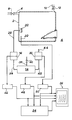
- the system shown schematically in this figure is intended to control the tightness of an enclosure 2, for example of the kind that are known under the name of "glove box".
- the environment surrounding the enclosure for example the air in a room in which this enclosure is located, bears the reference 4 in the figure.
- the enclosure 2 is provided with ventilation means comprising a pipe 6 allowing (thanks to a pump not shown) the entry of a gas such as air into the enclosure and provided with an isolation valve 8 thus that another pipe 10 intended for the evacuation of this gas (by means of another pump not shown) and also provided with an isolation valve 12.
- the system shown in the figure includes: a perfectly sealed reference chamber 14, a first differential pressure sensor 16, a second differential pressure sensor 20, a temperature sensor 22 placed inside the enclosure 2, first 46, second 48 and third 50 shaping means, electronic processing means 24 on which details will be given later, and - display means 26.
- the first differential pressure sensor 16 is connected to the interior of the enclosure 2 to be controlled by a pipe 28 the end of which opens into the enclosure 2 is provided with a filter 32 and inside the enclosure 14 by a line 34.
- the filter 32 is intended to prevent the penetration of aerosols which may be contained in the enclosure 2, in the pipe 28.
- the reference enclosure 14 communicates with the outside of the enclosure to be checked 2 by means of a pipe 38 which is provided with an isolation valve 40 and one end of which opens into the interior. of enclosure 14 while that the other end is open.
- the second differential pressure sensor 20 communicates with the inside of the enclosure 14 by a pipe 42 and with the outside of the enclosure to be checked 2 by a pipe 44 open to the outside of this enclosure 2.
- the outputs of the sensors 16, 20 and 22 are respectively connected to the inputs of the means 46, 48 and 50 provided for shaping and displaying the results of the measurements made by these sensors.
- the outputs of the means 46, 48 and 50 are connected to the electronic means 24 so that the results of the measurements are transmitted to these electronic means 24 in which the said results are first digitized (by means of analog-digital converters not shown) then processed, as will be seen later, in a microcomputer not shown, forming part of the electronic means 24.
- the outputs of the means 46, 48 and 50 are also connected to the display means 26 which consist, for example, of a four-channel recorder.
- the output of the electronic means 24 is also connected to this recorder.
- the enclosure is checked for leaks as follows: it is assumed that enclosure 2 is not in use and is at atmospheric pressure.
- the pipes 6, 10 and 28 are connected to it, the latter being for example of the flexible duct type and connected to the sensor 16, and the enclosure 2 is provided with the probe 22 connected to the shaping means 50.
- the power is turned on the electrical devices of the system, the valve 40 is opened and the system is allowed to stabilize for about fifteen minutes for example.
- the necessary zero adjustments are made (means for displaying the results, recorder), the valve 40 is closed, the enclosure 2 is put under overpressure (or under vacuum) using the ventilation means with which it is provided, means from which it is then isolated by closing the valves 8 and 12, and the system is allowed to stabilize for about fifteen minutes for example.
- the scrolling speed of the recorder is around 20 to 40 mm / h.
- the electrical devices of the system are put under tension, we open the valve 40, we let the system stabilize for about fifteen minutes for example - or less if the system has already worked before - we make the necessary zero adjustments, we close the valve 40 and we leave the system to stabilize for about fifteen minutes for example.
- the pressure prevailing inside the enclosure 14 serves as a reference pressure for the measurement of the internal differential pressure of the enclosure 2, carried out by means of the first sensor 16 and also as a reference pressure for the differential measurement of the pressure prevailing outside the enclosure 2 to be checked.
- the first sensor 16 preferably at high sensitivity, measures the variations, as a function of time, of the difference between the internal pressure of the enclosure to be checked 2 and the internal pressure of the reference enclosure 14.
- the sensor 20, preferably at high sensitivity measures the variations, as a function of time, of the difference between the pressure prevailing outside the enclosure to be checked 2 and the internal pressure of the reference enclosure 14.
- the sensor 22 for example constituted by a platinum probe, in turn measures the variations, as a function of time, of the internal temperature of the enclosure 2.
- the results of the measurements made by the sensors 16, 20 and 22 are respectively shaped and displayed by the means 46, 48 and 50 and the corresponding time variations are plotted by the recorder 26.
- differential pressure sensors have the following characteristics: - measuring range: 10 cm CE (Water column) - resolution: 0.01% full scale - accuracy: 0.15% of reading - time constant: 4.5 ms and the temperature sensor is a platinum probe, with a resistance of 100 ohms at 0 ° C, having a resolution of 0.1 ° C.
- the internal pressure, the temperature and the volume of the enclosure 2 are respectively denoted PB, TB AND VB, and the pressure in the room is denoted PC.
- N PB.VB. (R) ⁇ 1. (TB) ⁇ 1 (3)
- DPT1 PBT1 - PB0 quantity which is then compared to the measured internal differential pressure DP1, equal to PB1-PB0, at time t1.
- each deformed wall p (p varying between 1 and the number n of walls) to a spherical cap, intersection of a sphere of radius r by a plane located at a distance h p -r from the center of the sphere, h p thus representing the deflection of curvature of the wall considered, at time t.
- the quantity h p is a function of PC-PB. This function can be determined, knowing the enclosure considered.
- D the radius of the base circle of the spherical cap and we consider that D is equal to the diagonal D p of the wall p.
- the volume VP p generated by the deformation of the wall p at time t is such that: VP p (ft / 3) h 2 p (3R-h) or VP p (pi / 6) h p (3D 2 p + H 2 p )
- pi is the well-known number which is substantially equal to 3.141592.
- VBG VBG- (VP1 + VP2 + ... + VP p + VP p + ... + VP n ) in the event of overpressure of the enclosure (the sum VP1 + ... + VP n being on the contrary to be added in the event of depression of the enclosure).
Landscapes
- Physics & Mathematics (AREA)
- General Physics & Mathematics (AREA)
- Examining Or Testing Airtightness (AREA)
- Measuring Fluid Pressure (AREA)
Applications Claiming Priority (1)
| Application Number | Priority Date | Filing Date | Title |
|---|---|---|---|
| FR8803046A FR2628529B1 (fr) | 1988-03-09 | 1988-03-09 | Procede et systeme de controle de l'etancheite d'une enceinte |
Publications (1)
| Publication Number | Publication Date |
|---|---|
| EP0401447A1 true EP0401447A1 (de) | 1990-12-12 |
Family
ID=9364097
Family Applications (1)
| Application Number | Title | Priority Date | Filing Date |
|---|---|---|---|
| EP89401553A Ceased EP0401447A1 (de) | 1988-03-09 | 1989-06-06 | Verfahren und Vorrichtung zur Kontrolle der Dichtheit von einer Hülle. |
Country Status (2)
| Country | Link |
|---|---|
| EP (1) | EP0401447A1 (de) |
| FR (1) | FR2628529B1 (de) |
Cited By (5)
| Publication number | Priority date | Publication date | Assignee | Title |
|---|---|---|---|---|
| KR100326414B1 (ko) * | 1999-06-26 | 2002-02-28 | 윤순광 | 액정디스플레이 내구성 시험장치 |
| CN109937887A (zh) * | 2019-04-03 | 2019-06-28 | 苏州市冯氏实验动物设备有限公司 | 一种手术环境快速自清洁的生物安全手术箱及内循环方法 |
| CN115735106A (zh) * | 2020-06-29 | 2023-03-03 | 亚德克 | 泄漏检测方法和系统 |
| CN119714721A (zh) * | 2024-11-15 | 2025-03-28 | 中国辐射防护研究院 | 一种手套箱手套用泄漏率检测装置及检测方法 |
| EP4600625A1 (de) * | 2024-02-09 | 2025-08-13 | Syntegon Technology GmbH | Barrieresystem und verfahren zum betrieb eines barrieresystems |
Families Citing this family (3)
| Publication number | Priority date | Publication date | Assignee | Title |
|---|---|---|---|---|
| FR3031178B1 (fr) * | 2014-12-30 | 2018-04-20 | Isp Aquitaine | Dispositif de verification de l'etancheite |
| FR3125880B1 (fr) * | 2021-07-27 | 2023-10-27 | Ateq | Dispositif de détection de fuites pour pack batterie de véhicule automobile |
| FR3125881B1 (fr) * | 2021-07-27 | 2023-09-08 | Ateq | Dispositif de détection de fuites pour pack batterie de véhicule automobile |
Citations (5)
| Publication number | Priority date | Publication date | Assignee | Title |
|---|---|---|---|---|
| US3956923A (en) * | 1975-01-17 | 1976-05-18 | The Procter & Gamble Company | Method of detecting small gas leaks in filled aerosol containers |
| EP0139752A1 (de) * | 1983-03-18 | 1985-05-08 | Kabushiki Kaisha Kosumo Keiki | Auf Druckänderung ansprechende Leckprüfeinrichtung |
| US4523452A (en) * | 1984-04-23 | 1985-06-18 | Semyon Brayman | Method of measuring leak rates |
| EP0190059A1 (de) * | 1985-01-11 | 1986-08-06 | Novatome | Verfahren zur Feststellung von mittelgrossen und grossen Lecken in einer Wärmeaustauschfläche eines Dampferzeugers unter Verwendung flüssigen Metalls |
| US4686638A (en) * | 1983-11-04 | 1987-08-11 | Kabushiki Kaisha Kosumo Keiki | Leakage inspection method with object type compensation |
-
1988
- 1988-03-09 FR FR8803046A patent/FR2628529B1/fr not_active Expired - Lifetime
-
1989
- 1989-06-06 EP EP89401553A patent/EP0401447A1/de not_active Ceased
Patent Citations (5)
| Publication number | Priority date | Publication date | Assignee | Title |
|---|---|---|---|---|
| US3956923A (en) * | 1975-01-17 | 1976-05-18 | The Procter & Gamble Company | Method of detecting small gas leaks in filled aerosol containers |
| EP0139752A1 (de) * | 1983-03-18 | 1985-05-08 | Kabushiki Kaisha Kosumo Keiki | Auf Druckänderung ansprechende Leckprüfeinrichtung |
| US4686638A (en) * | 1983-11-04 | 1987-08-11 | Kabushiki Kaisha Kosumo Keiki | Leakage inspection method with object type compensation |
| US4523452A (en) * | 1984-04-23 | 1985-06-18 | Semyon Brayman | Method of measuring leak rates |
| EP0190059A1 (de) * | 1985-01-11 | 1986-08-06 | Novatome | Verfahren zur Feststellung von mittelgrossen und grossen Lecken in einer Wärmeaustauschfläche eines Dampferzeugers unter Verwendung flüssigen Metalls |
Non-Patent Citations (4)
| Title |
|---|
| PATENT ABSTRACTS OF JAPAN * |
| PATENT ABSTRACTS OF JAPAN, vol. 6, no. 100 (P-121)(978), 9 juin 1982; & JP-A-57 33337 * |
| SOVIET JOURNAL OF NONDESTRUCTIVE TESTING * |
| SOVIET JOURNAL OF NONDESTRUCTIVE TESTING, vol. 20, no. 6, juin 1984, pages 395-400, New York, USA; E.K. Dogonkina et al.: "Use of microcomputers in tests of vacuum tightness" * |
Cited By (8)
| Publication number | Priority date | Publication date | Assignee | Title |
|---|---|---|---|---|
| KR100326414B1 (ko) * | 1999-06-26 | 2002-02-28 | 윤순광 | 액정디스플레이 내구성 시험장치 |
| CN109937887A (zh) * | 2019-04-03 | 2019-06-28 | 苏州市冯氏实验动物设备有限公司 | 一种手术环境快速自清洁的生物安全手术箱及内循环方法 |
| CN115735106A (zh) * | 2020-06-29 | 2023-03-03 | 亚德克 | 泄漏检测方法和系统 |
| US20230280233A1 (en) * | 2020-06-29 | 2023-09-07 | Ateq | Leak detection method and system |
| US12366501B2 (en) * | 2020-06-29 | 2025-07-22 | Ateq | Leak detection method and system |
| CN115735106B (zh) * | 2020-06-29 | 2025-11-21 | 亚德克 | 泄漏检测方法和系统 |
| EP4600625A1 (de) * | 2024-02-09 | 2025-08-13 | Syntegon Technology GmbH | Barrieresystem und verfahren zum betrieb eines barrieresystems |
| CN119714721A (zh) * | 2024-11-15 | 2025-03-28 | 中国辐射防护研究院 | 一种手套箱手套用泄漏率检测装置及检测方法 |
Also Published As
| Publication number | Publication date |
|---|---|
| FR2628529A1 (fr) | 1989-09-15 |
| FR2628529B1 (fr) | 1990-11-09 |
Similar Documents
| Publication | Publication Date | Title |
|---|---|---|
| Kern et al. | Applying UV cameras for SO2 detection to distant or optically thick volcanic plumes | |
| US5082366A (en) | Apparatus and method for detecting leaks in packages | |
| US6519041B1 (en) | Hydrogen sensor for fuel cell applications | |
| CN112378956B (zh) | 一种低温气体湿度测量系统及方法 | |
| EP1366342B1 (de) | Pneumatischer füllstandsmesser und entsprechendes verfahren | |
| KR20090003195A (ko) | 배관로의 누설 검사 방법 및 누설 검사 장치 | |
| KR20080108544A (ko) | 누설 검사 방법 및 그것을 사용한 누설 검사 장치 | |
| WO2001059427A1 (fr) | Procede et dispositif non intrusif pour caracteriser les perturbations d'ecoulement d'un fluide a l'interieur d'une canalisation | |
| EP4172586B1 (de) | Leckdetektionsverfahren und -system | |
| FR2628529A1 (fr) | Procede et systeme de controle de l'etancheite d'une enceinte | |
| JP6426371B2 (ja) | 投込式水位計の校正システム、その校正方法、および校正機能付き投込式水位計 | |
| GB2054871A (en) | Measuring leakage rates | |
| JP7162301B2 (ja) | 圧力計の検査方法、および圧力計の検査装置 | |
| JP2010266282A (ja) | リークテスト装置及び方法 | |
| EP4449085B1 (de) | Verfahren und system zur leckerkennung | |
| KR102536949B1 (ko) | 가스 센서의 습도 보정 방법, 이를 이용한 가스 센서 및 자동식 소화기 | |
| EP1362229B1 (de) | Verfahren zur kalibrierung eines druckwandlers, insbesondere eines infraschall-druckwandlers | |
| EP3546697B1 (de) | Optisches abtastsystem | |
| JP3794584B2 (ja) | 配管の漏洩判別方法 | |
| Malcher et al. | A calculable pistonphone for the absolute calibration of hydrophones in the frequency range from 0.5 Hz to 250 Hz | |
| JPH1137883A (ja) | リーク量の計測方法 | |
| JP3366743B2 (ja) | 音響式管路長測定システム及びその温度補正装置 | |
| CA2064662C (fr) | Mesure de l'integrite et du taux de fuite d'un batiment hermetique | |
| JPH1114493A (ja) | ガス配管の気密試験方法および気密試験装置 | |
| US10571391B2 (en) | Method for adjusting a measuring device |
Legal Events
| Date | Code | Title | Description |
|---|---|---|---|
| PUAI | Public reference made under article 153(3) epc to a published international application that has entered the european phase |
Free format text: ORIGINAL CODE: 0009012 |
|
| AK | Designated contracting states |
Kind code of ref document: A1 Designated state(s): BE CH DE GB IT LI |
|
| 17P | Request for examination filed |
Effective date: 19910515 |
|
| 17Q | First examination report despatched |
Effective date: 19920310 |
|
| STAA | Information on the status of an ep patent application or granted ep patent |
Free format text: STATUS: THE APPLICATION HAS BEEN REFUSED |
|
| 18R | Application refused |
Effective date: 19921214 |