EP0401065B1 - Verfahren zur Herstellung einer wendelförmigen Verzögerungsleitung - Google Patents
Verfahren zur Herstellung einer wendelförmigen Verzögerungsleitung Download PDFInfo
- Publication number
- EP0401065B1 EP0401065B1 EP90401213A EP90401213A EP0401065B1 EP 0401065 B1 EP0401065 B1 EP 0401065B1 EP 90401213 A EP90401213 A EP 90401213A EP 90401213 A EP90401213 A EP 90401213A EP 0401065 B1 EP0401065 B1 EP 0401065B1
- Authority
- EP
- European Patent Office
- Prior art keywords
- construction
- travelling
- support
- supports
- dielectric
- Prior art date
- Legal status (The legal status is an assumption and is not a legal conclusion. Google has not performed a legal analysis and makes no representation as to the accuracy of the status listed.)
- Expired - Lifetime
Links
Images


Classifications
-
- H—ELECTRICITY
- H01—ELECTRIC ELEMENTS
- H01J—ELECTRIC DISCHARGE TUBES OR DISCHARGE LAMPS
- H01J23/00—Details of transit-time tubes of the types covered by group H01J25/00
- H01J23/16—Circuit elements, having distributed capacitance and inductance, structurally associated with the tube and interacting with the discharge
- H01J23/24—Slow-wave structures, e.g. delay systems
- H01J23/26—Helical slow-wave structures; Adjustment therefor
Definitions
- the present invention relates to a particular construction method which makes it possible to manufacture very wide band traveling wave tubes having a very low dispersion; this method of construction consists in supporting the helix of the delay line of a broadband traveling wave tube by means of dielectric supports ensuring the isolation arranged between the helix and fins or other metallic supports projecting towards the center from a metallic envelope which surrounds the whole.
- the invention also relates to a traveling wave tube manufactured according to this method of construction.
- TOP Progressive wave tubes
- TOP Progressive wave tubes
- the wide bandwidth allowed by the helix construction of the delay line results from the low dispersion of the electromagnetic waves which propagate along the helix delay line as a function of frequency; in other words, the speed v of the wave which propagates along the helical line depends very little on the frequency of the wave in a wide range of frequencies centered on the nominal operating frequency of the tube traveling waves.
- the coupling between the high frequency (HF) signal applied to the input of the tube and from there to the helical delay line and the electron beam depends on the synchronism of the propagation of the two along the longitudinal direction traveling wave tubes.
- the speed of the electron beam depends on the acceleration voltages created inside the tube, as a first approximation, and it is modified by the energy exchange that occurs with the electromagnetic field, in second approximation; if, as a first approximation, the speed of the high frequency wave which propagates along the propeller depends only on the geometry of the propeller, in second approximation, it also depends slightly on the frequency, which ultimately limits the bandwidth of the traveling wave tube.
- the use of traveling wave tubes in amplifier equipment does not allow the adjustment of operating voltages to modify the speed of the beam electrons when the frequency of the signal to be amplified varies, and it is therefore desirable to '' have as little variation as possible in the speed of the electromagnetic wave as a function of frequency.
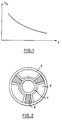
- Figure 1 shows a typical curve which represents the variation of the c / v ratio as a function of the wavelength, where c is the speed of light.
- a value of d approximately equal to unity means that the phase velocity along the delay line is practically constant when the frequency varies, which is the condition which must be fulfilled for broadband operation, if possible in full operating bandwidth.
- a very large value of d corresponds either to an infinite value of Vp (wave guided at the cutoff frequency), or to a value of Vg close to zero, which means that the energy does not propagate along the line at delay.
- the circuit stops transmitting energy in a propagation mode given at frequencies such that the half wavelength in this mode is equal to the period of the geometric characteristics of the delay line. These frequencies are called “cutoff frequencies in mode ⁇ ". There are also cutoff frequencies in zero mode when the phase difference over a period of the slow wave structure is equal to zero or a multiple of 2 ⁇ .
- cut-off frequencies can be displaced, but at the cost of a reduction in the efficiency of the traveling wave tube in operation: the intensity of the electric field is reduced for a given level of power. propagating in the delay line at a given phase velocity, which reduces interaction with the electron beam in the tube.
- the cut-off frequencies observed experimentally can be called "natural cut-off frequencies”.
- a method known in the prior art for reducing this drawback consists in adding an anisotropic charge to the basic helix delay line, which gives a very low dispersion which can even become zero or negative.
- FIG. 3 The best known of these methods of applying a load, illustrated in FIG. 3, consists in having metal fins in the shape of a U, with a capacitive effect, between the dielectric bars supporting the propeller, the ends of which are positioned very near the propeller (a few tenths of a millimeter). It is difficult to obtain economically reproducible results in an industrial manufacturing process when employing this process. This process generally requires the use of a difficult technique of soldering.
- Another method known in the prior art consists in disposing the capacitive charges between the dielectric bars supporting the helix, as shown in FIG. 2, but this solution reduces the coupling impedance of the circuit and the efficiency of the tube.
- Patent US-A-4 689 276 recommends brazing by the "diffusion bonding" method under pressure the dielectric supports on metal elements which project from the interior surface of the envelope.
- the object of the invention is therefore to obtain a higher cut-off frequency without the drawbacks of the methods of the prior art.
- the fundamental physical principles known in the prior art can be explained in a new construction method according to the invention, which gives a very low dispersion and, consequently, an enlarged useful bandwidth while lowering the industrial cost price and the complexity of the assembly and improving the reproducibility of the characteristics of the tube.
- the present invention relates to a method of constructing a traveling wave tube described in claim 1.
- said support elements are made of metallic material.
- the dielectric supports have the form of continuous bars which are at their tower supported by metal supports.
- the dimensions of the dielectric supports are thus smaller than those of the previous embodiment, which leads to an improvement in the thermal conductivity of the propeller to the envelope which surrounds the assembly.
- the dielectric supports have the form of discontinuous pads which are arranged between each turn of the propeller and a continuous metal support.
- These studs can be assembled on the metal support before introducing this sub-assembly into the envelope which surrounds the assembly, which improves the precision of the assembly and facilitates the manufacture of the tube.
- the reduced dimensions of the studs have the advantage of allowing the use of expensive materials such as diamond and boron nitride with a cubic network with centered faces, for example.
- the continuous metallic support is in the form of a vacuum-tight enveloping structure which, when it is placed inside the jacket surrounding the assembly, leaves a space between this outer jacket and said support structure, space in which a liquid or a cooling gas can be circulated.
- FIGS. 2, 3 and 4 included for explanatory purposes represent known embodiments of the prior art in which the propeller is supported in its vacuum-tight envelope 2 surrounding the assembly by means of dielectric bars 3, and metallic elements 4 are arranged in the space between the propeller and the envelope and between the dielectric supports in a symmetrical manner.
- FIG. 5 represents an example of a mode of construction of a traveling wave tube with a propeller according to the invention in which the propeller 1 is supported in its vacuum-tight envelope 2 surrounding the assembly by dielectric supports 3 ensuring the insulation which are in turn supported by metal elements 4 which project from the inner wall of the vacuum-tight envelope 2 surrounding the assembly, towards the helix and on which the dielectric supports are arranged.
- a groove is formed along the length of the dielectric support 3 so as to receive the edge of the metal element 4, which ensures the precision of the assembly and greatly simplifies the manufacturing process compared to the prior art.
- FIG. 6 represents another example of a construction of a traveling wave tube with a propeller according to the invention in which the propeller 1 is supported in its vacuum-tight envelope 2 surrounding the assembly, by dielectric supports 3 providing isolation, characterized in that the dielectric supports 3 are in turn supported by metal elements 4 which project from the inner wall of the vacuum-tight envelope 2 surrounding the assembly, towards the helix and on which the dielectric supports 3 are arranged.
- a groove is formed along the length of the metal element 4 so as to receive the edge of the T-shaped dielectric bar forming a support 3, which ensures assembly precision and greatly simplifies the manufacturing process compared to the prior art.
- the metal elements of Figures 5 and 6 may advantageously have the shape of a wedge whose thick end rests on the inner face of the vacuum-tight envelope 2 surrounding the assembly.
- FIG. 7 shows another example of a method of constructing a traveling wave tube with a propeller according to the invention in which the propeller is supported in its vacuum-tight envelope 2 surrounding the assembly by dielectric supports 3 ensuring insulation, characterized in that the dielectric supports 3 are in turn supported by metal elements 4 which project from the inner wall of the vacuum-tight envelope 2 surrounding the assembly, towards the helix and on which the dielectric supports 3 are arranged.
- the dielectric supports 3 are no longer continuous bars as in the two preceding examples of embodiment of the invention shown in FIGS.
- a groove is shaped in the dielectric material to receive the edge of the metal element 4, which ensures the accuracy of the assembly.
- dielectric pads can easily be imagined with the use of dielectric pads.
- a groove can be formed along the length of the metal element as in Figure 6 or local holes can be distributed along the length of the metal element to receive dielectric pads having a suitable protruding part to position and hold the studs in the groove or in the holes.
- FIG. 8 represents another example of a method of constructing a propeller traveling wave tube according to the invention in which the propeller 1 is supported in its vacuum-tight envelope 2 surrounding the assembly for dielectric supports ensuring the insulation 3, characterized in that the dielectric supports 3 are in turn supported by a metal element 4 which protrude relative to the inner wall of the vacuum-tight envelope 2 surrounding the assembly, towards the helix and on which the dielectric supports 3 are arranged.
- a groove is formed along the length of the dielectric supports 3 so as to receive the ribs forming supports of the metal element 4, which ensures the precision of the 'assembly and greatly simplifies the manufacturing process compared to the prior art.
- the metal elements 4 form a vacuum-tight envelope surrounding the propeller 1 and disposed inside the cylindrical outer envelope 2, defining and delimiting spaces 5 formed between the two envelopes, in which a gas or a liquid can be circulated to cool the delay line.
- metal elements 4 are used to support the dielectric elements 3 forming propeller supports ensuring isolation, but the invention also relates to a construction method applicable to the manufacture of propeller delay lines in which the metallic elements 4 are replaced by any other material having a finite electrical length, positioned in the immediate vicinity of the dielectric supports 3 so as to partially compensate for the capacitive charge effect of the dielectric at the frequencies close to the natural cutoff frequency. Likewise, the invention also relates to embodiments in which additional metallic elements can be arranged between the elements 4 which support the dielectric supports 3 of the helix 1.
Claims (9)
- Konstruktionsart für Wanderfeldröhren mit Spirale (1), wobei die Spirale in einer vakuumdichten Hülle (2) enthalten und von dielektrischen Trägern (3) getragen wird, die ihrerseits von Stützelementen (4) getragen werden, welche bezüglich der inneren Oberfläche der Hülle (2) vorstehen und eine begrenzte elektrische Länge in der unmittelbaren Nähe der dielektrischen Träger (3) besitzen, so daß die kapazitive Ladung dieser dielektrischen Träger (3) teilweise durch das Vorhandensein der Stützelemente (4) bei den Frequenzen in der Nähe der natürlichen Grenzfrequenz kompensiert wird, dadurch gekennzeichnet, daß die dielektrischen Träger und die Stützelemente so gestaltet sind, daß sie sich ineinander einfügen, um einen genauen Zusammenbau zu ermöglichen.
- Konstruktionsart für Wanderfeldröhren mit Spirale nach Anspruch 1, dadurch gekennzeichnet, daß die Stützelemente (4) mit begrenzter elektrischer Länge aus Metall sind.
- Konstruktionsart für Wanderfeldröhren nach einem der Ansprüche 1 oder 2, dadurch gekennzeichnet, daß die Stützelemente (4) mit begrenzter elektrischer Länge und die dielektrischen Stützen (3) so gestaltet sind, daß sie eine gegenseitige Verriegelung dieser Teile entlang der Länge der spiralförmigen Struktur bilden.
- Konstruktionsart für Wanderfeldröhren nach einem der Ansprüche 1 bis 3, dadurch gekennzeichnet, daß zusätzliche metallische Elemente zwischen den Stützelementen (4) begrenzter elektrischer Länge angeordnet sind.
- Konstruktionsart für Wanderfeldröhren mit Spirale nach einem der Ansprüche 1 bis 4, dadurch gekennzeichnet, daß die dielektrischen Träger die Form kontinuierlicher Pfosten haben.
- Konstruktionsart für Wanderfeldröhren mit Spirale nach einem der Ansprüche 1 bis 4, dadurch gekennzeichnet, daß die dielektrischen Träger (3) die Form von diskontinuierlichen Pflöcken haben.
- Konstruktionsart für Wanderfeldröhren mit Spirale nach einem der Ansprüche 1 bis 6, dadurch gekennzeichnet, daß die Stützelemente (4) mit begrenzter elektrischer Länge die Form von kontinuierlichen Pfosten haben.
- Konstruktionsart für Wanderfeldröhren mit Spirale nach einem der Ansprüche 2 bis 6, dadurch gekennzeichnet, daß die metallischen Stützelemente (4) die Form einer vakuumdichten kontinuierlichen Hülle haben.
- Konstruktionsart für Wanderfeldröhren mit Spirale nach Anspruch 8, dadurch gekennzeichnet, daß die vakuumdichte kontinuierliche metallische Hülle innerhalb der äußeren, das Ganze umgebenden Hülle (2) angeordnet ist und Räume erzeugt, in denen ein Gas oder eine Flüssigkeit in Umlauf gesetzt werden kann.
Applications Claiming Priority (2)
| Application Number | Priority Date | Filing Date | Title |
|---|---|---|---|
| FR8907081A FR2647953B1 (fr) | 1989-05-30 | 1989-05-30 | Mode de construction d'une ligne a retard a helice et tubes a ondes progressives utilisant ce mode de construction |
| FR8907081 | 1989-05-30 |
Publications (2)
| Publication Number | Publication Date |
|---|---|
| EP0401065A1 EP0401065A1 (de) | 1990-12-05 |
| EP0401065B1 true EP0401065B1 (de) | 1995-07-05 |
Family
ID=9382153
Family Applications (1)
| Application Number | Title | Priority Date | Filing Date |
|---|---|---|---|
| EP90401213A Expired - Lifetime EP0401065B1 (de) | 1989-05-30 | 1990-05-07 | Verfahren zur Herstellung einer wendelförmigen Verzögerungsleitung |
Country Status (5)
| Country | Link |
|---|---|
| US (1) | US5132592A (de) |
| EP (1) | EP0401065B1 (de) |
| JP (1) | JPH0320933A (de) |
| DE (1) | DE69020644T2 (de) |
| FR (1) | FR2647953B1 (de) |
Families Citing this family (8)
| Publication number | Priority date | Publication date | Assignee | Title |
|---|---|---|---|---|
| FR2663463B1 (fr) * | 1990-06-19 | 1992-09-11 | Thomson Tubes Electroniques | Tube a ondes progressives muni d'un dispositif de couplage entre sa ligne a retard et un circuit hyperfrequence externe. |
| JP2808912B2 (ja) * | 1991-04-01 | 1998-10-08 | 日本電気株式会社 | らせん形遅波回路構体 |
| US5341066A (en) * | 1992-09-02 | 1994-08-23 | Itt Corporation | Anisotropically loaded helix assembly for a traveling-wave tube |
| FR2758888B1 (fr) * | 1997-01-27 | 1999-04-23 | Thomson Csf | Procede de modelisation fine du fouillis de sol recu par un radar |
| FR2787918B1 (fr) * | 1998-12-23 | 2001-03-16 | Thomson Tubes Electroniques | Tube a ondes progressives multibande de longueur reduite capable de fonctionner a puissance elevee |
| FR2833749B1 (fr) * | 2001-12-14 | 2004-04-02 | Thales Sa | Refroidissement d'un tube electronique |
| JP2006134751A (ja) * | 2004-11-08 | 2006-05-25 | Nec Microwave Inc | 電子管 |
| JP2006210261A (ja) * | 2005-01-31 | 2006-08-10 | Mitsubishi Electric Corp | 遅波回路 |
Family Cites Families (15)
| Publication number | Priority date | Publication date | Assignee | Title |
|---|---|---|---|---|
| US2806170A (en) * | 1953-09-30 | 1957-09-10 | Rca Corp | Traveling wave tube |
| US2889487A (en) * | 1954-09-15 | 1959-06-02 | Hughes Aircraft Co | Traveling-wave tube |
| US3209198A (en) * | 1961-06-28 | 1965-09-28 | Sylvania Electric Prod | Resilient helix mount for traveling wave tube |
| US3271615A (en) * | 1961-08-23 | 1966-09-06 | Westinghouse Electric Corp | Traveling wave electron discharge device having means exerting a radial force upon the envelope |
| US3397339A (en) * | 1965-04-30 | 1968-08-13 | Varian Associates | Band edge oscillation suppression techniques for high frequency electron discharge devices incorporating slow wave circuits |
| US3421040A (en) * | 1966-11-03 | 1969-01-07 | Varian Associates | Circuit support for microwave tubes employing shaped dielectric supports rods to capture a ductile material at the support joints |
| US3691630A (en) * | 1969-12-10 | 1972-09-19 | James E Burgess | Method for supporting a slow wave circuit via an array of dielectric posts |
| US3972005A (en) * | 1969-12-16 | 1976-07-27 | Varian Associates | Ultrawide band traveling wave tube amplifier employing axially conductive circuit loading members |
| US3670196A (en) * | 1971-02-24 | 1972-06-13 | Raytheon Co | Helix delay line for traveling wave devices |
| IT1090547B (it) * | 1977-10-28 | 1985-06-26 | Elettronica Spa | Tubi ad onda progressiva ad elica con schermaggio ausiliario selettivo mediante elementi conduttori applicati su supporti dielettrici |
| FR2420842A1 (fr) * | 1978-03-24 | 1979-10-19 | Thomson Csf | Ligne a retard, pour tube hyperfrequences, refroidie par circulation de fluide et tube hyperfrequences comportant une telle ligne |
| US4278914A (en) * | 1979-10-18 | 1981-07-14 | The United States Of America As Represented By The Secretary Of The Navy | Diamond supported helix assembly and method |
| JPS5875738A (ja) * | 1981-10-30 | 1983-05-07 | Nippon Telegr & Teleph Corp <Ntt> | ヘリツクス形進行波管 |
| US4689276A (en) * | 1983-03-15 | 1987-08-25 | Varian Associates | Diamond bonded electronic circuit |
| DE58908993D1 (de) * | 1988-06-21 | 1995-03-23 | Thomson Tubes Electroniques | Herstellungsverfahren für eine Verzögerungsleitung für eine Wanderfeldröhre. |
-
1989
- 1989-05-30 FR FR8907081A patent/FR2647953B1/fr not_active Expired - Lifetime
-
1990
- 1990-05-07 DE DE69020644T patent/DE69020644T2/de not_active Expired - Fee Related
- 1990-05-07 EP EP90401213A patent/EP0401065B1/de not_active Expired - Lifetime
- 1990-05-23 US US07/528,052 patent/US5132592A/en not_active Expired - Lifetime
- 1990-05-24 JP JP2135171A patent/JPH0320933A/ja active Pending
Non-Patent Citations (1)
| Title |
|---|
| Elsevier's Dictionary of Electronics and Waveguides, Elsevier Scientific Publishing Company, Amsterdam 1966, page 190; * |
Also Published As
| Publication number | Publication date |
|---|---|
| JPH0320933A (ja) | 1991-01-29 |
| DE69020644D1 (de) | 1995-08-10 |
| US5132592A (en) | 1992-07-21 |
| FR2647953A1 (fr) | 1990-12-07 |
| DE69020644T2 (de) | 1995-11-30 |
| EP0401065A1 (de) | 1990-12-05 |
| FR2647953B1 (fr) | 1991-08-16 |
Similar Documents
| Publication | Publication Date | Title |
|---|---|---|
| EP0401065B1 (de) | Verfahren zur Herstellung einer wendelförmigen Verzögerungsleitung | |
| FR2471041A1 (fr) | Tube a ondes progressives a attenuateurs de longueur variable | |
| FR2504726A1 (fr) | Fenetre de guide d'ondes a forte puissance et a large bande, notamment pour tubes a micro-ondes | |
| FR3074364A1 (fr) | Charge interne pour tube a ondes progressives utilisant une ligne a retard en guide replie | |
| EP0995345B1 (de) | Vorrichtung zur anregung eines gases durch oberflächenwellenplasma | |
| FR3040242A1 (fr) | Systeme diviseur/combineur pour onde hyperfrequence | |
| EP0328948B1 (de) | Filter mit einem dielektrischen Resonator | |
| EP0048648B1 (de) | Wanderfeldröhrenverzögerungsleitung mit gekoppelten Hohlraumresonatoren und Wanderfeldröhre mit einer solchen Leitung | |
| EP0004492B1 (de) | Mikrowellenröhre mit einer durch Fluidumströmung gekühlten Verzögerungsleitung | |
| FR2543734A1 (fr) | Tube a onde progressive comportant un fourreau creuse de gorges et procede de fabrication | |
| EP0153541A1 (de) | Rundes Fernster für einen Mikrowellenhohlleiter | |
| EP0022016B1 (de) | Verzögerungsleitung mit veränderlicher Steghöhe für eine Wanderfeldröhre und Wanderfeldröhre mit einer solchen Verzögerungsleitung | |
| EP0499514B1 (de) | Modenwandler und Leistungsteiler-Einrichtung für eine Mikrowellenröhre, und Mikrowellenröhre mit einer solchen Einrichtung | |
| FR2501413A1 (fr) | Tube a vide du type gyrotron a stabilite elevee | |
| FR2471042A1 (fr) | Tube a ondes progressives du type a helice et a large bande passante | |
| EP0100707B1 (de) | Wellenleiter-Gas-Laserquelle | |
| EP1579469B1 (de) | Mikrowellenröhre mit mechanischer frequenzabstimmung | |
| EP1145268B1 (de) | Hochleistungsfähiges mehrband-wandelfeldrohr mit reduzierter länge | |
| FR2790595A1 (fr) | Circuit de ligne a retard en helice | |
| FR2661559A1 (fr) | Convertisseur de mode de propagation guidee des ondes electromagnetiques et tube electronique comportant un tel convertisseur. | |
| EP2202774B1 (de) | Angepasster Übergang eines RF-Ausgangs für leistungsfähige elektronische Hyperfrequenzröhre | |
| FR2688342A1 (fr) | Tube electronique hyperfrequence. | |
| FR2563389A1 (fr) | Dispositifs amplificateurs et oscillateurs micro-ondes | |
| EP1466343A2 (de) | Elektronenröhre mit einem mit einer axialen pumpspitze versehen kollektor | |
| FR2597265A1 (fr) | Structure de guide d'ondes helicoidale pour un tube a ondes progressives et son procede de fabrication |
Legal Events
| Date | Code | Title | Description |
|---|---|---|---|
| PUAI | Public reference made under article 153(3) epc to a published international application that has entered the european phase |
Free format text: ORIGINAL CODE: 0009012 |
|
| AK | Designated contracting states |
Kind code of ref document: A1 Designated state(s): DE FR GB IT |
|
| 17P | Request for examination filed |
Effective date: 19901217 |
|
| 17Q | First examination report despatched |
Effective date: 19930630 |
|
| GRAA | (expected) grant |
Free format text: ORIGINAL CODE: 0009210 |
|
| AK | Designated contracting states |
Kind code of ref document: B1 Designated state(s): DE FR GB IT |
|
| ITF | It: translation for a ep patent filed |
Owner name: JACOBACCI & PERANI S.P.A. |
|
| REF | Corresponds to: |
Ref document number: 69020644 Country of ref document: DE Date of ref document: 19950810 |
|
| GBT | Gb: translation of ep patent filed (gb section 77(6)(a)/1977) |
Effective date: 19950915 |
|
| PGFP | Annual fee paid to national office [announced via postgrant information from national office to epo] |
Ref country code: DE Payment date: 19960425 Year of fee payment: 7 |
|
| PLBE | No opposition filed within time limit |
Free format text: ORIGINAL CODE: 0009261 |
|
| STAA | Information on the status of an ep patent application or granted ep patent |
Free format text: STATUS: NO OPPOSITION FILED WITHIN TIME LIMIT |
|
| 26N | No opposition filed | ||
| PG25 | Lapsed in a contracting state [announced via postgrant information from national office to epo] |
Ref country code: DE Free format text: LAPSE BECAUSE OF NON-PAYMENT OF DUE FEES Effective date: 19980203 |
|
| REG | Reference to a national code |
Ref country code: GB Ref legal event code: IF02 |
|
| PGFP | Annual fee paid to national office [announced via postgrant information from national office to epo] |
Ref country code: FR Payment date: 20090515 Year of fee payment: 20 Ref country code: IT Payment date: 20090516 Year of fee payment: 20 |
|
| PGFP | Annual fee paid to national office [announced via postgrant information from national office to epo] |
Ref country code: GB Payment date: 20090506 Year of fee payment: 20 |
|
| REG | Reference to a national code |
Ref country code: GB Ref legal event code: PE20 Expiry date: 20100506 |
|
| PG25 | Lapsed in a contracting state [announced via postgrant information from national office to epo] |
Ref country code: GB Free format text: LAPSE BECAUSE OF EXPIRATION OF PROTECTION Effective date: 20100506 |