EP0401065B1 - Method of construction of a helical delay line - Google Patents
Method of construction of a helical delay line Download PDFInfo
- Publication number
- EP0401065B1 EP0401065B1 EP90401213A EP90401213A EP0401065B1 EP 0401065 B1 EP0401065 B1 EP 0401065B1 EP 90401213 A EP90401213 A EP 90401213A EP 90401213 A EP90401213 A EP 90401213A EP 0401065 B1 EP0401065 B1 EP 0401065B1
- Authority
- EP
- European Patent Office
- Prior art keywords
- construction
- travelling
- support
- supports
- dielectric
- Prior art date
- Legal status (The legal status is an assumption and is not a legal conclusion. Google has not performed a legal analysis and makes no representation as to the accuracy of the status listed.)
- Expired - Lifetime
Links
Images


Classifications
-
- H—ELECTRICITY
- H01—ELECTRIC ELEMENTS
- H01J—ELECTRIC DISCHARGE TUBES OR DISCHARGE LAMPS
- H01J23/00—Details of transit-time tubes of the types covered by group H01J25/00
- H01J23/16—Circuit elements, having distributed capacitance and inductance, structurally associated with the tube and interacting with the discharge
- H01J23/24—Slow-wave structures, e.g. delay systems
- H01J23/26—Helical slow-wave structures; Adjustment therefor
Definitions
- the present invention relates to a particular construction method which makes it possible to manufacture very wide band traveling wave tubes having a very low dispersion; this method of construction consists in supporting the helix of the delay line of a broadband traveling wave tube by means of dielectric supports ensuring the isolation arranged between the helix and fins or other metallic supports projecting towards the center from a metallic envelope which surrounds the whole.
- the invention also relates to a traveling wave tube manufactured according to this method of construction.
- TOP Progressive wave tubes
- TOP Progressive wave tubes
- the wide bandwidth allowed by the helix construction of the delay line results from the low dispersion of the electromagnetic waves which propagate along the helix delay line as a function of frequency; in other words, the speed v of the wave which propagates along the helical line depends very little on the frequency of the wave in a wide range of frequencies centered on the nominal operating frequency of the tube traveling waves.
- the coupling between the high frequency (HF) signal applied to the input of the tube and from there to the helical delay line and the electron beam depends on the synchronism of the propagation of the two along the longitudinal direction traveling wave tubes.
- the speed of the electron beam depends on the acceleration voltages created inside the tube, as a first approximation, and it is modified by the energy exchange that occurs with the electromagnetic field, in second approximation; if, as a first approximation, the speed of the high frequency wave which propagates along the propeller depends only on the geometry of the propeller, in second approximation, it also depends slightly on the frequency, which ultimately limits the bandwidth of the traveling wave tube.
- the use of traveling wave tubes in amplifier equipment does not allow the adjustment of operating voltages to modify the speed of the beam electrons when the frequency of the signal to be amplified varies, and it is therefore desirable to '' have as little variation as possible in the speed of the electromagnetic wave as a function of frequency.
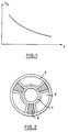
- Figure 1 shows a typical curve which represents the variation of the c / v ratio as a function of the wavelength, where c is the speed of light.
- a value of d approximately equal to unity means that the phase velocity along the delay line is practically constant when the frequency varies, which is the condition which must be fulfilled for broadband operation, if possible in full operating bandwidth.
- a very large value of d corresponds either to an infinite value of Vp (wave guided at the cutoff frequency), or to a value of Vg close to zero, which means that the energy does not propagate along the line at delay.
- the circuit stops transmitting energy in a propagation mode given at frequencies such that the half wavelength in this mode is equal to the period of the geometric characteristics of the delay line. These frequencies are called “cutoff frequencies in mode ⁇ ". There are also cutoff frequencies in zero mode when the phase difference over a period of the slow wave structure is equal to zero or a multiple of 2 ⁇ .
- cut-off frequencies can be displaced, but at the cost of a reduction in the efficiency of the traveling wave tube in operation: the intensity of the electric field is reduced for a given level of power. propagating in the delay line at a given phase velocity, which reduces interaction with the electron beam in the tube.
- the cut-off frequencies observed experimentally can be called "natural cut-off frequencies”.
- a method known in the prior art for reducing this drawback consists in adding an anisotropic charge to the basic helix delay line, which gives a very low dispersion which can even become zero or negative.
- FIG. 3 The best known of these methods of applying a load, illustrated in FIG. 3, consists in having metal fins in the shape of a U, with a capacitive effect, between the dielectric bars supporting the propeller, the ends of which are positioned very near the propeller (a few tenths of a millimeter). It is difficult to obtain economically reproducible results in an industrial manufacturing process when employing this process. This process generally requires the use of a difficult technique of soldering.
- Another method known in the prior art consists in disposing the capacitive charges between the dielectric bars supporting the helix, as shown in FIG. 2, but this solution reduces the coupling impedance of the circuit and the efficiency of the tube.
- Patent US-A-4 689 276 recommends brazing by the "diffusion bonding" method under pressure the dielectric supports on metal elements which project from the interior surface of the envelope.
- the object of the invention is therefore to obtain a higher cut-off frequency without the drawbacks of the methods of the prior art.
- the fundamental physical principles known in the prior art can be explained in a new construction method according to the invention, which gives a very low dispersion and, consequently, an enlarged useful bandwidth while lowering the industrial cost price and the complexity of the assembly and improving the reproducibility of the characteristics of the tube.
- the present invention relates to a method of constructing a traveling wave tube described in claim 1.
- said support elements are made of metallic material.
- the dielectric supports have the form of continuous bars which are at their tower supported by metal supports.
- the dimensions of the dielectric supports are thus smaller than those of the previous embodiment, which leads to an improvement in the thermal conductivity of the propeller to the envelope which surrounds the assembly.
- the dielectric supports have the form of discontinuous pads which are arranged between each turn of the propeller and a continuous metal support.
- These studs can be assembled on the metal support before introducing this sub-assembly into the envelope which surrounds the assembly, which improves the precision of the assembly and facilitates the manufacture of the tube.
- the reduced dimensions of the studs have the advantage of allowing the use of expensive materials such as diamond and boron nitride with a cubic network with centered faces, for example.
- the continuous metallic support is in the form of a vacuum-tight enveloping structure which, when it is placed inside the jacket surrounding the assembly, leaves a space between this outer jacket and said support structure, space in which a liquid or a cooling gas can be circulated.
- FIGS. 2, 3 and 4 included for explanatory purposes represent known embodiments of the prior art in which the propeller is supported in its vacuum-tight envelope 2 surrounding the assembly by means of dielectric bars 3, and metallic elements 4 are arranged in the space between the propeller and the envelope and between the dielectric supports in a symmetrical manner.
- FIG. 5 represents an example of a mode of construction of a traveling wave tube with a propeller according to the invention in which the propeller 1 is supported in its vacuum-tight envelope 2 surrounding the assembly by dielectric supports 3 ensuring the insulation which are in turn supported by metal elements 4 which project from the inner wall of the vacuum-tight envelope 2 surrounding the assembly, towards the helix and on which the dielectric supports are arranged.
- a groove is formed along the length of the dielectric support 3 so as to receive the edge of the metal element 4, which ensures the precision of the assembly and greatly simplifies the manufacturing process compared to the prior art.
- FIG. 6 represents another example of a construction of a traveling wave tube with a propeller according to the invention in which the propeller 1 is supported in its vacuum-tight envelope 2 surrounding the assembly, by dielectric supports 3 providing isolation, characterized in that the dielectric supports 3 are in turn supported by metal elements 4 which project from the inner wall of the vacuum-tight envelope 2 surrounding the assembly, towards the helix and on which the dielectric supports 3 are arranged.
- a groove is formed along the length of the metal element 4 so as to receive the edge of the T-shaped dielectric bar forming a support 3, which ensures assembly precision and greatly simplifies the manufacturing process compared to the prior art.
- the metal elements of Figures 5 and 6 may advantageously have the shape of a wedge whose thick end rests on the inner face of the vacuum-tight envelope 2 surrounding the assembly.
- FIG. 7 shows another example of a method of constructing a traveling wave tube with a propeller according to the invention in which the propeller is supported in its vacuum-tight envelope 2 surrounding the assembly by dielectric supports 3 ensuring insulation, characterized in that the dielectric supports 3 are in turn supported by metal elements 4 which project from the inner wall of the vacuum-tight envelope 2 surrounding the assembly, towards the helix and on which the dielectric supports 3 are arranged.
- the dielectric supports 3 are no longer continuous bars as in the two preceding examples of embodiment of the invention shown in FIGS.
- a groove is shaped in the dielectric material to receive the edge of the metal element 4, which ensures the accuracy of the assembly.
- dielectric pads can easily be imagined with the use of dielectric pads.
- a groove can be formed along the length of the metal element as in Figure 6 or local holes can be distributed along the length of the metal element to receive dielectric pads having a suitable protruding part to position and hold the studs in the groove or in the holes.
- FIG. 8 represents another example of a method of constructing a propeller traveling wave tube according to the invention in which the propeller 1 is supported in its vacuum-tight envelope 2 surrounding the assembly for dielectric supports ensuring the insulation 3, characterized in that the dielectric supports 3 are in turn supported by a metal element 4 which protrude relative to the inner wall of the vacuum-tight envelope 2 surrounding the assembly, towards the helix and on which the dielectric supports 3 are arranged.
- a groove is formed along the length of the dielectric supports 3 so as to receive the ribs forming supports of the metal element 4, which ensures the precision of the 'assembly and greatly simplifies the manufacturing process compared to the prior art.
- the metal elements 4 form a vacuum-tight envelope surrounding the propeller 1 and disposed inside the cylindrical outer envelope 2, defining and delimiting spaces 5 formed between the two envelopes, in which a gas or a liquid can be circulated to cool the delay line.
- metal elements 4 are used to support the dielectric elements 3 forming propeller supports ensuring isolation, but the invention also relates to a construction method applicable to the manufacture of propeller delay lines in which the metallic elements 4 are replaced by any other material having a finite electrical length, positioned in the immediate vicinity of the dielectric supports 3 so as to partially compensate for the capacitive charge effect of the dielectric at the frequencies close to the natural cutoff frequency. Likewise, the invention also relates to embodiments in which additional metallic elements can be arranged between the elements 4 which support the dielectric supports 3 of the helix 1.
Description
La présente invention concerne un mode de construction particulier qui permet de fabriquer des tubes à ondes progressives à très large bande ayant une très faible dispersion ; ce mode de construction consiste à supporter l'hélice de la ligne à retard d'un tube à ondes progressives à large bande au moyen de supports diélectriques assurant l'isolement disposés entre l'hélice et des ailettes ou autres supports métalliques en saillie vers le centre à partir d'une enveloppe métallique qui entoure l'ensemble.The present invention relates to a particular construction method which makes it possible to manufacture very wide band traveling wave tubes having a very low dispersion; this method of construction consists in supporting the helix of the delay line of a broadband traveling wave tube by means of dielectric supports ensuring the isolation arranged between the helix and fins or other metallic supports projecting towards the center from a metallic envelope which surrounds the whole.
L'invention concerne également un tube à ondes progressives fabriqué selon ce mode de construction.The invention also relates to a traveling wave tube manufactured according to this method of construction.
Les tubes à ondes progressives (TOP) sont bien connus dans l'art antérieur et sont préférés aux autres tubes hyperfréquence pour les applications qui nécessitent une très large bande passante intrinsèque en amplification. La large bande passante permise par la construction en hélice de la ligne à retard résulte de la faible dispersion des ondes électromagnétiques qui se propagent le long de la ligne à retard à hélice en fonction de la fréquence ; en d'autres termes, la vitesse v de l'onde qui se propage le long de la ligne en hélice ne dépend que très peu de la fréquence de l'onde dans une large gamme de fréquences centrée sur la fréquence nominale de fonctionnement du tube à ondes progressives.Progressive wave tubes (TOP) are well known in the prior art and are preferred to other microwave tubes for applications which require a very large intrinsic passband in amplification. The wide bandwidth allowed by the helix construction of the delay line results from the low dispersion of the electromagnetic waves which propagate along the helix delay line as a function of frequency; in other words, the speed v of the wave which propagates along the helical line depends very little on the frequency of the wave in a wide range of frequencies centered on the nominal operating frequency of the tube traveling waves.
Le couplage entre le signal à haute fréquence (HF) appliqué à l'entrée du tube et, de là, à la ligne à retard à hélice et le faisceau d'électrons dépend du synchronisme de la propagation des deux le long de la direction longitudinale du tubes à ondes progressives. La vitesse du faisceau d'électrons dépend des tensions d'accélération créées à l'intérieur du tube, en première approximation, et elle est modifiée par l'échange d'énergie qui se produit avec le champ électromagnétique, en seconde approximation ; si, en première approximation, la vitesse de l'onde à haute fréquence qui se propage le long de l'hélice ne dépend que de la géométrie de l'hélice, en seconde approximation, elle dépend en outre légèrement de la fréquence, ce qui limite finalement la bande passante du tube à ondes progressives.The coupling between the high frequency (HF) signal applied to the input of the tube and from there to the helical delay line and the electron beam depends on the synchronism of the propagation of the two along the longitudinal direction traveling wave tubes. The speed of the electron beam depends on the acceleration voltages created inside the tube, as a first approximation, and it is modified by the energy exchange that occurs with the electromagnetic field, in second approximation; if, as a first approximation, the speed of the high frequency wave which propagates along the propeller depends only on the geometry of the propeller, in second approximation, it also depends slightly on the frequency, which ultimately limits the bandwidth of the traveling wave tube.
Pour des raisons pratiques, l'utilisation des tubes à ondes progressives dans un équipement amplificateur ne permet pas le réglage des tensions de fonctionnement pour modifier la vitesse des électrons du faisceau lorsque la fréquence du signal à amplifier varie, et il est par conséquent souhaitable d'avoir une variation aussi faible que possible de la vitesse de l'onde électromagnétique en fonction de la fréquence. Cependant, dans tous les modes de construction pratique d'une ligne à retard, la vitesse de phase de l'onde électromagnétique dépend de la fréquence, ce qui donne naissance à une dispersion d = Vp/Vg, où Vp est la vitesse de phase le long de la ligne à retard à la fréquence de fonctionnement et Vg est la vitesse de groupe.For practical reasons, the use of traveling wave tubes in amplifier equipment does not allow the adjustment of operating voltages to modify the speed of the beam electrons when the frequency of the signal to be amplified varies, and it is therefore desirable to '' have as little variation as possible in the speed of the electromagnetic wave as a function of frequency. However, in all practical modes of construction of a delay line, the phase speed of the electromagnetic wave depends on the frequency, which gives rise to a dispersion d = Vp / Vg, where Vp is the phase speed along the delay line at the operating frequency and Vg is the group speed.
La figure 1 reproduit une courbe typique qui représente la variation du rapport c/v en fonction de la longueur d'onde, où c est la vitesse de la lumière. Une valeur de d approximativement égale à l'unité signifie que la vitesse de phase le long de la ligne à retard est pratiquement constante lorsque la fréquence varie, ce qui est la condition qui doit être remplie pour le fonctionnement à large bande, si possible dans toute la largeur de bande de fonctionnement. Une très grande valeur de d correspond soit à une valeur infinie de Vp (onde guidée à la fréquence de coupure), soit à une valeur de Vg proche de zéro, qui signifie que l'énergie ne se propage pas le long de la ligne à retard.Figure 1 shows a typical curve which represents the variation of the c / v ratio as a function of the wavelength, where c is the speed of light. A value of d approximately equal to unity means that the phase velocity along the delay line is practically constant when the frequency varies, which is the condition which must be fulfilled for broadband operation, if possible in full operating bandwidth. A very large value of d corresponds either to an infinite value of Vp (wave guided at the cutoff frequency), or to a value of Vg close to zero, which means that the energy does not propagate along the line at delay.
En pratique, pour tout circuit à propagation d'onde (ici, la ligne à retard) ayant des caractéristiques géométriques ou électriques périodiques, le circuit cesse de transmettre l'énergie dans un mode de propagation donné au fréquences telles que la demi-longueur d'onde dans ce mode est égale à la période des caractéristiques géométriques de la ligne à retard. Ces fréquences sont appelées "fréquences de coupure en mode ¶". Il existe également des fréquences de coupure en mode zéro lorsque la différence de phase sur une période de la structure à onde lente est égale à zéro ou à un multiple de 2¶.In practice, for any wave propagation circuit (here, the delay line) having periodic geometric or electrical characteristics, the circuit stops transmitting energy in a propagation mode given at frequencies such that the half wavelength in this mode is equal to the period of the geometric characteristics of the delay line. These frequencies are called "cutoff frequencies in mode ¶". There are also cutoff frequencies in zero mode when the phase difference over a period of the slow wave structure is equal to zero or a multiple of 2¶.
A ces fréquences, la dispersion telle qu'elle est définie plus haut tend vers l'infini. Ces fréquences de coupure ne peuvent être évitées dans un circuit physique parce que Vg ne peut croître indéfiniment au fur et à mesure que Vp croît indéfiniment, pas plus que Vg ne peut être empêché de devenir infinitésimalement petit pour une valeur finie de Vp.At these frequencies, the dispersion as defined above tends towards infinity. These cutoff frequencies cannot be avoided in a physical circuit because Vg cannot grow indefinitely as Vp grows indefinitely, any more than Vg cannot be prevented from becoming infinitesimally small for a finite value of Vp.
Dans l'art antérieur, il est connu que ces fréquences de coupure peuvent être déplacées, mais au prix d'une diminution du rendement du tube à ondes progressives en fonctionnement : l'intensité du champ électrique est réduite pour un niveau donné de la puissance se propageant dans la ligne à retard à une vitesse de phase donnée, ce qui réduit l'interaction avec le faisceau d'électrons dans le tube. Dans le cas où les fréquences de coupure ne sont déplacées par aucun moyen, les fréquences de coupure observées expérimentalement peuvent être appelées "fréquences de coupure naturelles".In the prior art, it is known that these cut-off frequencies can be displaced, but at the cost of a reduction in the efficiency of the traveling wave tube in operation: the intensity of the electric field is reduced for a given level of power. propagating in the delay line at a given phase velocity, which reduces interaction with the electron beam in the tube. In the case where the cut-off frequencies are not displaced by any means, the cut-off frequencies observed experimentally can be called "natural cut-off frequencies".
Un procédé connu dans l'art antérieur pour réduire cet inconvénient consiste à ajouter une charge anisotrope à la ligne à retard à hélice de base, ce qui donne une très faible dispersion qui peut même devenir nulle ou négative.A method known in the prior art for reducing this drawback consists in adding an anisotropic charge to the basic helix delay line, which gives a very low dispersion which can even become zero or negative.
Le plus connu de ces procédés d'application d'une charge, illustrée par la figure 3, consiste à disposer des ailettes métalliques en forme de U, à effet capacitif, entre les barreaux diélectriques supportant l'hélice, dont les extrémités sont positionnées très près de l'hélice (quelques dixièmes de millimètre). Il est difficile d'obtenir des résultats reproductibles économiquement dans un processus de fabrication industrielle lorsque l'on emploie ce procédé. Ce procédé nécessite généralement de recourir à une difficile technique du brasage.The best known of these methods of applying a load, illustrated in FIG. 3, consists in having metal fins in the shape of a U, with a capacitive effect, between the dielectric bars supporting the propeller, the ends of which are positioned very near the propeller (a few tenths of a millimeter). It is difficult to obtain economically reproducible results in an industrial manufacturing process when employing this process. This process generally requires the use of a difficult technique of soldering.
Un autre procédé connu dans l'art antérieur consiste à disposer des charges capacitives entre les barreaux diélectriques supportant l'hélice, comme cela est présenté sur la figure 2, mais cette solution réduit l'impédance de couplage du circuit et le rendement du tube.Another method known in the prior art consists in disposing the capacitive charges between the dielectric bars supporting the helix, as shown in FIG. 2, but this solution reduces the coupling impedance of the circuit and the efficiency of the tube.
Un autre procédé connu consiste à remplacer les ailettes mises en formes du U mentionnées plus haut et représentées sur la figure 3, par des métallisations localisées des barreaux diélectriques supportant l'hélice, comme cela est représentée sur la figure 4 et est décrit dans le brevet US-A-4 264 842. Ce procédé est également difficile à mettre en oeuvre industriellement si l'on veut obtenir économiquement des résultats reproductibles.Another known method consists in replacing the fins formed in the form of the U mentioned above and represented in FIG. 3, by localized metallizations of the dielectric bars supporting the propeller, as shown in FIG. 4 and is described in the patent. US-A-4 264 842. This process is also difficult to implement industrially if it is desired to obtain reproducible results economically.
Le brevet US-A-4 689 276 préconise de braser par la méthode de "diffusion bonding" sous pression les supports diélectriques sur des éléments métalliques qui sont en saillie par rapport à la surface intérieure de l'enveloppe .Patent US-A-4 689 276 recommends brazing by the "diffusion bonding" method under pressure the dielectric supports on metal elements which project from the interior surface of the envelope.
L'invention a donc pour but d'obtenir une fréquence de coupure plus élevée sans les inconvénients des procédés de l'art antérieur. Les principes physiques fondamentaux connus dans l'art antérieur peuvent être explicités dans un nouveau mode de construction selon l'invention, ce qui donne une très faible dispersion et, par conséquent, une bande passante utile élargie tout en abaissant le prix de revient industriel et la complexité de l'ensemble et en améliorant la reproductibilité des caractéristiques du tube. La présente invention concerne un mode de construction d'un tube à ondes progressives décrit dans la revendication 1.The object of the invention is therefore to obtain a higher cut-off frequency without the drawbacks of the methods of the prior art. The fundamental physical principles known in the prior art can be explained in a new construction method according to the invention, which gives a very low dispersion and, consequently, an enlarged useful bandwidth while lowering the industrial cost price and the complexity of the assembly and improving the reproducibility of the characteristics of the tube. The present invention relates to a method of constructing a traveling wave tube described in
Selon une forme de réalisation préférée de l'invention, lesdits éléments formant supports sont en matière métallique.According to a preferred embodiment of the invention, said support elements are made of metallic material.
Selon une forme de réalisation de l'invention, les supports diélectriques ont la forme de barreaux continus qui sont à leur tour supportés par des supports métalliques. Les dimensions des supports diélectriques sont ainsi plus petites que celles de la forme de réalisation précédente, ce qui conduit à une amélioration de la conductibilité thermique de l'hélice à l'enveloppe qui entoure l'ensemble.According to one embodiment of the invention, the dielectric supports have the form of continuous bars which are at their tower supported by metal supports. The dimensions of the dielectric supports are thus smaller than those of the previous embodiment, which leads to an improvement in the thermal conductivity of the propeller to the envelope which surrounds the assembly.
Selon une autre forme de réalisation de l'invention, les supports diélectriques ont la forme de plots discontinus qui sont disposés entre chaque spire de l'hélice et un support métallique continu. Ces plots peuvent être assemblés sur le support métallique avant d'introduire ce sous-ensemble dans l'enveloppe qui entoure l'ensemble, ce qui améliore la précision de l'assemblage et facilite la fabrication du tube. De plus, les dimensions réduites des plots ont l'avantage de permettre l'emploi de matériaux coûteux tels que le diamant et le nitrure de bore à réseau cubique à faces centrées, par exemple.According to another embodiment of the invention, the dielectric supports have the form of discontinuous pads which are arranged between each turn of the propeller and a continuous metal support. These studs can be assembled on the metal support before introducing this sub-assembly into the envelope which surrounds the assembly, which improves the precision of the assembly and facilitates the manufacture of the tube. In addition, the reduced dimensions of the studs have the advantage of allowing the use of expensive materials such as diamond and boron nitride with a cubic network with centered faces, for example.
Selon une autre forme de réalisation de l'invention, le support métallique continu se présente sous la forme d'une structure enveloppante étanche au vide qui, lorsqu'elle est disposée à l'intérieur de la chemise entourant l'ensemble, laisse un espace entre cette chemise extérieure et ladite structure formant support, espace dans lequel un liquide ou un gaz de refroidissement peut être mis en circulation.According to another embodiment of the invention, the continuous metallic support is in the form of a vacuum-tight enveloping structure which, when it is placed inside the jacket surrounding the assembly, leaves a space between this outer jacket and said support structure, space in which a liquid or a cooling gas can be circulated.
D'autres caractéristiques et avantages de l'invention apparaîtront à la lecture de la description détaillée d'exemples de réalisation non limitatifs donnée ci-après en relation avec les dessins annexés, dans lesquels :
- la figure 1, déjà décrite plus haut, reproduit une courbe typique représentant la variation du rapport de la vitesse de la lumière c à la vitesse v de propagation de l'énergie le long de la longueur de la structure à onde lente en hélice en fonction de la longueur d'onde lambda, en unités arbitraires ;
- la figure 2, déjà décrite plus haut, est une vue en coupe transversale d'un mode de construction d'une ligne à retard à hélice de l'art antérieur dans lequel l'hélice est supportée par des barreaux diélectriques formant supports à l'intérieur d'une enveloppe cylindrique étanche au vide entourant l'ensemble, et dans lequel les barreaux diélectriques formant supports sont en contact tant avec l'hélice qu'avec l'enveloppe, et ces "ailettes" métalliques massives à charge capacitive sont disposées entre les barreaux diélectriques formant supports dans l'espace compris entre l'enveloppe et l'hélice ;
- la figure 3, déjà décrite plus haut, représente une vue en coupe transversale d'un autre mode de construction d'une ligne à retard à hélice de l'art antérieur, dans lequel l'hélice est supportée par des barreaux diélectriques formant supports en contact avec l'hélice et avec une enveloppe cylindrique étanche au vide entourant l'ensemble comme sur la figure 2, avec des ailettes en forme de U disposées entre les barreaux diélectriques formant supports fixées à la paroi intérieure de l'enveloppe étanche au vide et en saillie vers l'hélice jusqu'à une faible distance de celle-ci ;
- la figure 4, déjà décrite plus haute, est une vue en coupe transversale d'un autre mode de construction d'une ligne à retard à hélice de l'art antérieur, dans lequel l'hélice est supportée par des barreaux diélectriques formant supports en contact avec l'hélice et avec une enveloppe cylindrique étanche au vide entourant l'ensemble comme sur la figure 2, avec des métallisations localisées déposées sur les faces des barreaux diélectriquées qui font face à l'espace situé entre l'hélice et l'enveloppe ;
- la figure 5 est une vue en coupe transversale d'une forme de réalisation d'un mode de construction d'une ligne à retard à hélice selon l'invention, dans lequel des barreaux diélectriquées en forme de U formant supports sont disposés entre l'hélice et des supports métalliques qui sont en saillie par rapport à la paroi intérieure de l'enveloppe cylindrique à vide entourant l'ensemble, vers l'hélice ;
- la figure 6 est une vue en coupe transversale d'une autre forme de réalisation d'un mode de construction d'une ligne à retard à hélice selon l'invention, dans lequel des barreaux diélectriques en forme de T formant supports sont disposés entre l'hélice et des supports métalliques rainurés qui sont en saillie par rapport à la paroi intérieure de l'enveloppe cylindrique étanche au vide entourant l'ensemble; vers l'hélice ;
- la figure 7 est une vue en perspective d'un détail d'une autre forme de réalisation d'un mode de construction d'une ligne à retard à hélice selon l'invention, dans lequel l'hélice est supportée par des plots diélectriques qui sont disposés entre l'hélice et des supports métalliques qui sont en saillie par rapport à la paroi intérieure de l'enveloppe cylindrique étanche au vide entourant l'ensemble, vers l'hélice ; et,
- la figure 8 est une vue en coupe transversale d'une autre forme de réalisation d'un mode de construction d'une ligne à retard en hélice selon l'invention, dans lequel des barreaux diélectriques formant supports ou des plots sont disposés entre l'hélice et une structure métallique étanche au vide entourant l'ensemble qui est à son tour disposée à l'intérieur d'une enveloppe cylindrique entourant l'ensemble et créant des espaces entre elle-même et la structure formant support, dans lesquels un liquide ou un gaz de refroidissement peut être mis en circulation.
- FIG. 1, already described above, reproduces a typical curve representing the variation of the ratio of the speed of light c to the speed v of energy propagation along the length of the slow wave structure in helix as a function lambda wavelength, in arbitrary units;
- Figure 2, already described above, is a cross-sectional view of a construction method of a propeller delay line of the prior art in which the propeller is supported by dielectric bars forming supports at the inside a vacuum-tight cylindrical envelope surrounding the assembly, and in which the dielectric bars forming supports are in contact with both the helix and the envelope, and these massive metal "fins" with capacitive load are arranged between the dielectric bars forming supports in the space between the casing and the propeller;
- Figure 3, already described above, shows a cross-sectional view of another embodiment of a propeller delay line of the prior art, in which the propeller is supported by dielectric bars forming supports in contact with the propeller and with a vacuum-tight cylindrical envelope surrounding the assembly as in FIG. 2, with U-shaped fins arranged between the dielectric bars forming supports fixed to the interior wall of the vacuum-tight envelope and projecting towards the propeller to a small distance from it;
- Figure 4, already described above, is a cross-sectional view of another embodiment of a propeller delay line of the prior art, in which the propeller is supported by dielectric bars forming supports in contact with the propeller and with a vacuum-tight cylindrical envelope surrounding the assembly as in Figure 2, with localized metallizations deposited on the faces of the dielectric bars which face the space between the propeller and the envelope ;
- Figure 5 is a cross-sectional view of a shape of an embodiment of a propeller delay line according to the invention, in which U-shaped dielectric bars forming supports are arranged between the propeller and metal supports which project from the inner wall of the cylindrical vacuum envelope surrounding the assembly, towards the propeller;
- Figure 6 is a cross-sectional view of another embodiment of an embodiment of a propeller delay line according to the invention, in which T-shaped dielectric bars forming supports are arranged between the propeller and grooved metal supports which project from the inner wall of the vacuum tight cylindrical envelope surrounding the assembly; towards the propeller;
- FIG. 7 is a perspective view of a detail of another embodiment of an embodiment of a propeller delay line according to the invention, in which the propeller is supported by dielectric pads which are arranged between the propeller and metal supports which project from the inner wall of the vacuum-tight cylindrical envelope surrounding the assembly, towards the propeller; and,
- Figure 8 is a cross-sectional view of another embodiment of an embodiment of a helical delay line according to the invention, in which dielectric bars forming supports or studs are arranged between the helix and a vacuum-tight metallic structure surrounding the assembly which is in turn arranged inside a cylindrical envelope surrounding the assembly and creating spaces between itself and the support structure, in which a liquid or cooling gas can be circulated.
En référence aux dessins, dans lesquels les mêmes références numériques désignent les mêmes éléments dans les différentes formes de réalisation, les figures 2, 3 et 4 incluses à titre explicatif, représentent des réalisations connues de l'art antérieur dans lesquelles l'hélice est supportée dans son enveloppe étanche au vide 2 entourant l'ensemble au moyen de barreaux diélectriques 3, et des éléments métalliques 4 sont disposés dans l'espace situé entre l'hélice et l'enveloppe et entre les supports diélectriques d'une manière symétrique.With reference to the drawings, in which the same numerical references designate the same elements in the various embodiments, FIGS. 2, 3 and 4 included for explanatory purposes represent known embodiments of the prior art in which the propeller is supported in its vacuum-
La figure 5 représente un exemple d'un mode de construction d'un tube à ondes progressives à hélice selon l'invention dans lequel l'hélice 1 est supportée dans son enveloppe étanche au vide 2 entourant l'ensemble par des supports diélectriques 3 assurant l'isolement qui sont à leur tour supportés par des éléments métalliques 4 qui sont en saillie par rapport à la paroi intérieure de l'enveloppe étanche au vide 2 entourant l'ensemble, vers l'hélice et sur lesquels les supports diélectriques sont disposés. Dans l'exemple de réalisation de l'invention représenté sur la figure 5, une rainure est façonnée le long de la longueur du support diélectrique 3 de manière à recevoir le chant de l'élément métallique 4, ce qui assure la précision de l'assemblage et simplifie grandement le processus de fabrication par rapport à l'art antérieur.FIG. 5 represents an example of a mode of construction of a traveling wave tube with a propeller according to the invention in which the
La figure 6 représente un autre exemple d'un mode de construction d'un tube à ondes progressives à hélice selon l'invention dans lequel l'hélice 1 est supportée dans son enveloppe étanche au vide 2 entourant l'ensemble, par des supports diélectriques 3 assurant l'isolement, caractérisé en ce que les supports diélectriques 3 sont à leur tour supportés par des éléments métalliques 4 qui sont en saillie par rapport à la paroi intérieure de l'enveloppe étanche au vide 2 entourant l'ensemble, vers l'hélice et sur lesquels les supports diélectriques 3 sont disposés. Dans cet exemple de réalisation de l'invention représenté sur la figure 6, une rainure est façonnée le long de la longueur de l'élément métallique 4 de manière à recevoir le chant du barreau diélectrique en forme de T formant support 3, ce qui assure la précision de l'assemblage et simplifie grandement le processus de fabrication par rapport à l'art antérieur.FIG. 6 represents another example of a construction of a traveling wave tube with a propeller according to the invention in which the
Les éléments métalliques des figures 5 et 6 peuvent avantageusement avoir la forme d'un coin dont l'extrémité épaisse repose sur la face intérieure de l'enveloppe étanche au vide 2 entourant l'ensemble.The metal elements of Figures 5 and 6 may advantageously have the shape of a wedge whose thick end rests on the inner face of the vacuum-
La figure 7 représente un autre exemple d'un mode de construction d'un tube à ondes progressives à hélice selon l'invention dans lequel l'hélice est supportée dans son enveloppe étanche au vide 2 entourant l'ensemble par des supports diélectriques 3 assurant l'isolement, caractérisé en ce que les support diélectriques 3 sont à leur tour supportés par des éléments métalliques 4 qui sont en saillie par rapport à la paroi intérieure de l'enveloppe étanche au vide 2 entourant l'ensemble, vers l'hélice et sur lesquels les supports diélectriques 3 sont disposés. Dans l'exemple de réalisation de l'invention représenté sur la figure 7, les supports diélectriques 3 ne sont plus des barreaux continus comme dans les deux exemples précédents de réalisation de l'invention représentés sur les figures 5 et 6, et sont au contraire disconstinus et formés par des plots diélectriques assurant l'isolement et positionnés le long de la longueur de l'élément métallique continu 4 de telle manière qu'ils supportent chaque spire de l'hélice individuelle. Comme dans l'exemple de réalisation de l'invention représenté sur la figure 5 et décrit plus haut, une rainure est façonnée dans le matériau diélectrique pour recevoir le chant de l'élément métallique 4, ce qui assure la précision de l'assemblage. D'autres modes de réalisation peuvent facilement être imaginés avec utilisation de plots diélectriques. Par exemple, une rainure peut être façonnée le long de la longueur de l'élément métallique comme sur la figure 6 ou des trous locaux peuvent être répartis le long de la longueur de l'élément métallique pour recevoir des plots diélectriques ayant une partie protubérante convenant pour positionner et maintenir les plots dans la rainure ou dans les trous.FIG. 7 shows another example of a method of constructing a traveling wave tube with a propeller according to the invention in which the propeller is supported in its vacuum-
La figure 8 représente un autre exemple d'un mode de construction d'un tube à ondes progressives à hélice selon l'invention dans lequel l'hélice 1 est supportée dans son enveloppe étanche au vide 2 entourant l'ensemble pour des supports diélectrique assurant l'isolement 3, caractérisé en ce que les supports diélectriques 3 sont à leur tour supportés par un élément métallique 4 qui sont en saillie par rapport à la paroi intérieure de l'enveloppe étanche au vide 2 entourant l'ensemble, vers l'hélice et sur lequel les supports diélectriques 3 sont disposés. Dans cet exemple de réalisation de l'invention représenté sur la figure 8, une rainure est façonnée le long de la longueur des supports diélectriques 3 de manière à recevoir les nervures formant supports de l'élément métallique 4, ce qui assure la précision de l'assemblage et simplifie grandement le processus de fabrication par rapport à l'art antérieur. L'exemple de réalisation selon l'invention représenté sur la figure 8 est en outre caractérisé en ce que les éléments métalliques 4 forment une enveloppe étanche au vide entourant l'hélice 1 et disposée à l'intérieur de l'enveloppe extérieure cylindrique 2, définissant et délimitant des espaces 5 formés entre les deux enveloppes, dans lesquels un gaz ou un liquide peut être mis en circulation pour refroidir la ligne à retard.FIG. 8 represents another example of a method of constructing a propeller traveling wave tube according to the invention in which the
Dans plusieurs formes de réalisation préférées de l'invention telles qu'elles sont représentées par les exemples non limitatifs décrits ci-dessus et les figures correspondantes 5, 6, 7 et 8, des éléments métalliques 4 sont utilisés pour supporter les éléments diélectriques 3 formant supports de l'hélice en assurant l'isolement, mais l'invention concerne également un mode de construction applicable à la fabrication des lignes à retard à hélice dans lequel les éléments métalliques 4 sont remplacés par tout autre matériau ayant une longueur électrique finie, positionné à proximité immédiate des supports diélectriques 3 de manière à compenser partiellement l'effet de charge capacitive du diélectrique aux fréquences proches de la fréquence de coupure naturelle. De même, l'invention concerne en outre des formes de réalisation dans lesquelles des éléments métalliques supplémentaires peuvent être disposés entre les éléments 4 qui supportent les supports diélectrique 3 de l'hélice 1.In several preferred embodiments of the invention as shown by the nonlimiting examples described above and the corresponding figures 5, 6, 7 and 8,
Dans tous les cas, il est entendu que les montages décrits plus haut n'illustrent qu'un petit nombre des nombreuses formes de réalisation spécifiques possibles qui peuvent représenter des applications des principes de l'invention. D'autres montages, nombreux et variés, peuvent facilement être imaginés en conformité avec ces principes par l'homme de métier sans sortir du cadre de l'invention telle qu'elle est définie dans les revendications.In all cases, it is understood that the arrangements described above illustrate only a small number of the many possible specific embodiments which may represent applications of the principles of the invention. Other arrangements, numerous and varied, can easily be imagined in accordance with these principles by those skilled in the art without departing from the scope of the invention as defined in the claims.
Claims (9)
- Method of construction of travelling-wave tubes with a helix (1), the helix (1) being contained in a vacuum-tight envelope (2) and being supported by dielectric supports (3), these dielectric supports themselves being supported by support-forming elements (4) projecting with respect to the inner surface of the envelope (2), these elements (4) having a finite electrical length in immediate proximity to the dielectric supports (3) such that the capacitive load of these dielectric supports (3) is partially compensated for by the presence of the support-forming elements (4) at frequencies close to the natural cut-off frequency, characterized in that the dielectric supports and the support-forming elements are fashioned in such a way as to fit into one another in order to achieve a compact assembly.
- Method of construction of travelling-wave tubes with a helix according to Claim 1, characterized in that the support-forming elements (4) with finite electrical length are of metallic material.
- Method of construction of travelling-wave tubes according to one of Claims 1 or 2, characterized in that the support-forming elements (4) with finite electrical length and the dielectric supports (3) are fashioned in such a way as to produce a mutual locking of these components along the length of the helical structure.
- Method of construction of travelling-wave tubes according to one of Claims 1 to 3, characterized in that the supplementary metallic elements are arranged between the support-forming elements (4) with finite electrical length.
- Method of construction of travelling-wave tubes with a helix according to one of Claims 1 to 4, characterized in that the dielectric supports have the form of continuous bars.
- Method of construction of travelling-wave tubes with a helix according to one of Claims 1 to 4, characterized in that the dielectric supports (3) have the form of discontinuous pads.
- Method of construction of travelling-wave tubes with a helix according to one of Claims 1 to 6, characterized in that the support-forming elements (4) with finite electrical length have the form of continuous bars.
- Method of construction of travelling-wave tubes with a helix according to one of Claims 2 to 6, characterized in that the support-forming metallic elements (4) have the form of a continuous, vacuum-tight envelope.
- Method of construction of travelling-wave tubes with a helix according to Claim 8, characterized in that the continuous, vacuum-tight metallic envelope, when it is arranged within the outer envelope (2) surrounding the assembly, creates spaces in which a gas or a liquid can be made to flow.
Applications Claiming Priority (2)
| Application Number | Priority Date | Filing Date | Title |
|---|---|---|---|
| FR8907081A FR2647953B1 (en) | 1989-05-30 | 1989-05-30 | MODEL OF CONSTRUCTION OF A PROPELLER DELAY LINE AND PROGRESSIVE WAVE TUBES USING THIS MODEL |
| FR8907081 | 1989-05-30 |
Publications (2)
| Publication Number | Publication Date |
|---|---|
| EP0401065A1 EP0401065A1 (en) | 1990-12-05 |
| EP0401065B1 true EP0401065B1 (en) | 1995-07-05 |
Family
ID=9382153
Family Applications (1)
| Application Number | Title | Priority Date | Filing Date |
|---|---|---|---|
| EP90401213A Expired - Lifetime EP0401065B1 (en) | 1989-05-30 | 1990-05-07 | Method of construction of a helical delay line |
Country Status (5)
| Country | Link |
|---|---|
| US (1) | US5132592A (en) |
| EP (1) | EP0401065B1 (en) |
| JP (1) | JPH0320933A (en) |
| DE (1) | DE69020644T2 (en) |
| FR (1) | FR2647953B1 (en) |
Families Citing this family (8)
| Publication number | Priority date | Publication date | Assignee | Title |
|---|---|---|---|---|
| FR2663463B1 (en) * | 1990-06-19 | 1992-09-11 | Thomson Tubes Electroniques | PROGRESSIVE WAVE TUBE PROVIDED WITH A COUPLING DEVICE BETWEEN ITS DELAYED LINE AND AN EXTERNAL MICROWAVE CIRCUIT. |
| JP2808912B2 (en) * | 1991-04-01 | 1998-10-08 | 日本電気株式会社 | Spiral slow-wave circuit structure |
| US5341066A (en) * | 1992-09-02 | 1994-08-23 | Itt Corporation | Anisotropically loaded helix assembly for a traveling-wave tube |
| FR2758888B1 (en) * | 1997-01-27 | 1999-04-23 | Thomson Csf | PROCESS FOR FINE MODELING OF CLOUD GROUND RECEIVED BY RADAR |
| FR2787918B1 (en) * | 1998-12-23 | 2001-03-16 | Thomson Tubes Electroniques | MULTIBAND PROGRESSIVE WAVE TUBE OF REDUCED LENGTH CAPABLE OF OPERATING AT HIGH POWER |
| FR2833749B1 (en) * | 2001-12-14 | 2004-04-02 | Thales Sa | COOLING OF AN ELECTRONIC TUBE |
| JP2006134751A (en) * | 2004-11-08 | 2006-05-25 | Nec Microwave Inc | Electron tube |
| JP2006210261A (en) * | 2005-01-31 | 2006-08-10 | Mitsubishi Electric Corp | Slow-wave circuit |
Family Cites Families (15)
| Publication number | Priority date | Publication date | Assignee | Title |
|---|---|---|---|---|
| US2806170A (en) * | 1953-09-30 | 1957-09-10 | Rca Corp | Traveling wave tube |
| US2889487A (en) * | 1954-09-15 | 1959-06-02 | Hughes Aircraft Co | Traveling-wave tube |
| US3209198A (en) * | 1961-06-28 | 1965-09-28 | Sylvania Electric Prod | Resilient helix mount for traveling wave tube |
| US3271615A (en) * | 1961-08-23 | 1966-09-06 | Westinghouse Electric Corp | Traveling wave electron discharge device having means exerting a radial force upon the envelope |
| US3397339A (en) * | 1965-04-30 | 1968-08-13 | Varian Associates | Band edge oscillation suppression techniques for high frequency electron discharge devices incorporating slow wave circuits |
| US3421040A (en) * | 1966-11-03 | 1969-01-07 | Varian Associates | Circuit support for microwave tubes employing shaped dielectric supports rods to capture a ductile material at the support joints |
| US3691630A (en) * | 1969-12-10 | 1972-09-19 | James E Burgess | Method for supporting a slow wave circuit via an array of dielectric posts |
| US3972005A (en) * | 1969-12-16 | 1976-07-27 | Varian Associates | Ultrawide band traveling wave tube amplifier employing axially conductive circuit loading members |
| US3670196A (en) * | 1971-02-24 | 1972-06-13 | Raytheon Co | Helix delay line for traveling wave devices |
| IT1090547B (en) * | 1977-10-28 | 1985-06-26 | Elettronica Spa | PROGRESSIVE WAVER HELICAL PIPES WITH SELECTIVE AUXILIARY SHIELDING USING CONDUCTIVE ELEMENTS APPLIED ON DIELECTRIC SUPPORTS |
| FR2420842A1 (en) * | 1978-03-24 | 1979-10-19 | Thomson Csf | DELAY LINE, FOR HYPERFREQUENCY TUBE, COOLED BY FLUID CIRCULATION AND HYPERFREQUENCY TUBE CONTAINING SUCH A LINE |
| US4278914A (en) * | 1979-10-18 | 1981-07-14 | The United States Of America As Represented By The Secretary Of The Navy | Diamond supported helix assembly and method |
| JPS5875738A (en) * | 1981-10-30 | 1983-05-07 | Nippon Telegr & Teleph Corp <Ntt> | Helix type traveling-wave tube |
| US4689276A (en) * | 1983-03-15 | 1987-08-25 | Varian Associates | Diamond bonded electronic circuit |
| DE58908993D1 (en) * | 1988-06-21 | 1995-03-23 | Thomson Tubes Electroniques | Manufacturing method for a delay line for a traveling wave tube. |
-
1989
- 1989-05-30 FR FR8907081A patent/FR2647953B1/en not_active Expired - Lifetime
-
1990
- 1990-05-07 EP EP90401213A patent/EP0401065B1/en not_active Expired - Lifetime
- 1990-05-07 DE DE69020644T patent/DE69020644T2/en not_active Expired - Fee Related
- 1990-05-23 US US07/528,052 patent/US5132592A/en not_active Expired - Lifetime
- 1990-05-24 JP JP2135171A patent/JPH0320933A/en active Pending
Non-Patent Citations (1)
| Title |
|---|
| Elsevier's Dictionary of Electronics and Waveguides, Elsevier Scientific Publishing Company, Amsterdam 1966, page 190; * |
Also Published As
| Publication number | Publication date |
|---|---|
| FR2647953A1 (en) | 1990-12-07 |
| DE69020644D1 (en) | 1995-08-10 |
| DE69020644T2 (en) | 1995-11-30 |
| JPH0320933A (en) | 1991-01-29 |
| EP0401065A1 (en) | 1990-12-05 |
| FR2647953B1 (en) | 1991-08-16 |
| US5132592A (en) | 1992-07-21 |
Similar Documents
| Publication | Publication Date | Title |
|---|---|---|
| EP0401065B1 (en) | Method of construction of a helical delay line | |
| FR2471041A1 (en) | PROGRESSIVE WAVE TUBE WITH ATTENUATORS OF VARIABLE LENGTH | |
| FR2504726A1 (en) | WIDE WAVEGUIDE GUIDE WINDOW AND BROADBAND, IN PARTICULAR FOR MICROWAVE TUBES | |
| EP0995345B1 (en) | Gas excitation device with surface wave plasma | |
| FR3040242A1 (en) | DIVIDER / COMBINER SYSTEM FOR MICROWAVE WAVE | |
| EP0328948B1 (en) | Filter using a dielectric resonator | |
| EP0048648B1 (en) | Coupled cavities delay line for a travelling-wave tube, and travelling-wave tube comprising such a line | |
| EP0004492B1 (en) | Microwave tube containing a delay line cooled by a circulating fluid | |
| FR2543734A1 (en) | PROGRESSIVE WAVE TUBE HAVING A HOLLOW GROOVE SLEEVE AND METHOD OF MANUFACTURE | |
| EP0153541A1 (en) | Circular window for a microwave waveguide | |
| EP0022016B1 (en) | Slow-wave structure with varying pitch for a travelling-wave tube, and travelling-wave tube using such a slow-wave structure | |
| EP0499514B1 (en) | Mode converter and power-dividing device for a microwave tube, and microwave tube with such a device | |
| FR2501413A1 (en) | HIGH STABILITY GYROTRON VACUUM TUBE | |
| EP0100707B1 (en) | Waveguide gas laser source | |
| EP1579469B1 (en) | Micro-wave tube with mechanical frequency tuning | |
| EP1466343B1 (en) | Electronic tube with simplified collector | |
| EP1145268B1 (en) | Multiband travelling wave tube of reduced length capable of high power functioning | |
| FR2737042A1 (en) | ELECTRON MULTI-STAGE ELECTRON COLLECTOR SUPPORTING HIGH VOLTAGES AND ELECTRONIC TUBE PROVIDED WITH SUCH A COLLECTOR | |
| FR2790595A1 (en) | Helix type slow wave circuit for traveling wave tube, has rectangular cross sectional support with holes, having dielectric to fix helix in vacuum envelope | |
| FR2661559A1 (en) | ELECTROMAGNETIC WAVE PROPAGATION MODE CONVERTER AND ELECTRONIC TUBE COMPRISING SUCH A CONVERTER. | |
| EP2202774B1 (en) | RF output fitted transition for microwave frequency electronic power tube | |
| FR2688342A1 (en) | Microwave electron tube | |
| FR2563389A1 (en) | MICROWAVE AMPLIFIER AND OSCILLATOR DEVICES | |
| FR2597265A1 (en) | HELICOIDAL WAVEGUIDE STRUCTURE FOR PROGRESSIVE WAVE TUBE AND METHOD FOR MANUFACTURING THE SAME | |
| FR2573915A1 (en) | METHOD AND DEVICE FOR PRODUCING AN ELECTRON BEAM |
Legal Events
| Date | Code | Title | Description |
|---|---|---|---|
| PUAI | Public reference made under article 153(3) epc to a published international application that has entered the european phase |
Free format text: ORIGINAL CODE: 0009012 |
|
| AK | Designated contracting states |
Kind code of ref document: A1 Designated state(s): DE FR GB IT |
|
| 17P | Request for examination filed |
Effective date: 19901217 |
|
| 17Q | First examination report despatched |
Effective date: 19930630 |
|
| GRAA | (expected) grant |
Free format text: ORIGINAL CODE: 0009210 |
|
| AK | Designated contracting states |
Kind code of ref document: B1 Designated state(s): DE FR GB IT |
|
| ITF | It: translation for a ep patent filed |
Owner name: JACOBACCI & PERANI S.P.A. |
|
| REF | Corresponds to: |
Ref document number: 69020644 Country of ref document: DE Date of ref document: 19950810 |
|
| GBT | Gb: translation of ep patent filed (gb section 77(6)(a)/1977) |
Effective date: 19950915 |
|
| PGFP | Annual fee paid to national office [announced via postgrant information from national office to epo] |
Ref country code: DE Payment date: 19960425 Year of fee payment: 7 |
|
| PLBE | No opposition filed within time limit |
Free format text: ORIGINAL CODE: 0009261 |
|
| STAA | Information on the status of an ep patent application or granted ep patent |
Free format text: STATUS: NO OPPOSITION FILED WITHIN TIME LIMIT |
|
| 26N | No opposition filed | ||
| PG25 | Lapsed in a contracting state [announced via postgrant information from national office to epo] |
Ref country code: DE Free format text: LAPSE BECAUSE OF NON-PAYMENT OF DUE FEES Effective date: 19980203 |
|
| REG | Reference to a national code |
Ref country code: GB Ref legal event code: IF02 |
|
| PGFP | Annual fee paid to national office [announced via postgrant information from national office to epo] |
Ref country code: FR Payment date: 20090515 Year of fee payment: 20 Ref country code: IT Payment date: 20090516 Year of fee payment: 20 |
|
| PGFP | Annual fee paid to national office [announced via postgrant information from national office to epo] |
Ref country code: GB Payment date: 20090506 Year of fee payment: 20 |
|
| REG | Reference to a national code |
Ref country code: GB Ref legal event code: PE20 Expiry date: 20100506 |
|
| PG25 | Lapsed in a contracting state [announced via postgrant information from national office to epo] |
Ref country code: GB Free format text: LAPSE BECAUSE OF EXPIRATION OF PROTECTION Effective date: 20100506 |