EP0400339A2 - Vorrichtung zur Herstellung verstärkter Polymerrohre - Google Patents
Vorrichtung zur Herstellung verstärkter Polymerrohre Download PDFInfo
- Publication number
- EP0400339A2 EP0400339A2 EP90108199A EP90108199A EP0400339A2 EP 0400339 A2 EP0400339 A2 EP 0400339A2 EP 90108199 A EP90108199 A EP 90108199A EP 90108199 A EP90108199 A EP 90108199A EP 0400339 A2 EP0400339 A2 EP 0400339A2
- Authority
- EP
- European Patent Office
- Prior art keywords
- housing
- die
- material guide
- guide sleeve
- polymeric
- Prior art date
- Legal status (The legal status is an assumption and is not a legal conclusion. Google has not performed a legal analysis and makes no representation as to the accuracy of the status listed.)
- Granted
Links
Images
Classifications
-
- B—PERFORMING OPERATIONS; TRANSPORTING
- B29—WORKING OF PLASTICS; WORKING OF SUBSTANCES IN A PLASTIC STATE IN GENERAL
- B29C—SHAPING OR JOINING OF PLASTICS; SHAPING OF MATERIAL IN A PLASTIC STATE, NOT OTHERWISE PROVIDED FOR; AFTER-TREATMENT OF THE SHAPED PRODUCTS, e.g. REPAIRING
- B29C48/00—Extrusion moulding, i.e. expressing the moulding material through a die or nozzle which imparts the desired form; Apparatus therefor
- B29C48/25—Component parts, details or accessories; Auxiliary operations
- B29C48/30—Extrusion nozzles or dies
- B29C48/32—Extrusion nozzles or dies with annular openings, e.g. for forming tubular articles
- B29C48/34—Cross-head annular extrusion nozzles, i.e. for simultaneously receiving moulding material and the preform to be coated
-
- B—PERFORMING OPERATIONS; TRANSPORTING
- B29—WORKING OF PLASTICS; WORKING OF SUBSTANCES IN A PLASTIC STATE IN GENERAL
- B29C—SHAPING OR JOINING OF PLASTICS; SHAPING OF MATERIAL IN A PLASTIC STATE, NOT OTHERWISE PROVIDED FOR; AFTER-TREATMENT OF THE SHAPED PRODUCTS, e.g. REPAIRING
- B29C48/00—Extrusion moulding, i.e. expressing the moulding material through a die or nozzle which imparts the desired form; Apparatus therefor
- B29C48/03—Extrusion moulding, i.e. expressing the moulding material through a die or nozzle which imparts the desired form; Apparatus therefor characterised by the shape of the extruded material at extrusion
- B29C48/09—Articles with cross-sections having partially or fully enclosed cavities, e.g. pipes or channels
-
- B—PERFORMING OPERATIONS; TRANSPORTING
- B29—WORKING OF PLASTICS; WORKING OF SUBSTANCES IN A PLASTIC STATE IN GENERAL
- B29C—SHAPING OR JOINING OF PLASTICS; SHAPING OF MATERIAL IN A PLASTIC STATE, NOT OTHERWISE PROVIDED FOR; AFTER-TREATMENT OF THE SHAPED PRODUCTS, e.g. REPAIRING
- B29C48/00—Extrusion moulding, i.e. expressing the moulding material through a die or nozzle which imparts the desired form; Apparatus therefor
- B29C48/15—Extrusion moulding, i.e. expressing the moulding material through a die or nozzle which imparts the desired form; Apparatus therefor incorporating preformed parts or layers, e.g. extrusion moulding around inserts
- B29C48/151—Coating hollow articles
- B29C48/152—Coating hollow articles the inner surfaces thereof
- B29C48/153—Coating both inner and outer surfaces
-
- B—PERFORMING OPERATIONS; TRANSPORTING
- B29—WORKING OF PLASTICS; WORKING OF SUBSTANCES IN A PLASTIC STATE IN GENERAL
- B29C—SHAPING OR JOINING OF PLASTICS; SHAPING OF MATERIAL IN A PLASTIC STATE, NOT OTHERWISE PROVIDED FOR; AFTER-TREATMENT OF THE SHAPED PRODUCTS, e.g. REPAIRING
- B29C48/00—Extrusion moulding, i.e. expressing the moulding material through a die or nozzle which imparts the desired form; Apparatus therefor
- B29C48/25—Component parts, details or accessories; Auxiliary operations
- B29C48/30—Extrusion nozzles or dies
- B29C48/32—Extrusion nozzles or dies with annular openings, e.g. for forming tubular articles
- B29C48/325—Extrusion nozzles or dies with annular openings, e.g. for forming tubular articles being adjustable, i.e. having adjustable exit sections
- B29C48/327—Extrusion nozzles or dies with annular openings, e.g. for forming tubular articles being adjustable, i.e. having adjustable exit sections with centering means
-
- B—PERFORMING OPERATIONS; TRANSPORTING
- B29—WORKING OF PLASTICS; WORKING OF SUBSTANCES IN A PLASTIC STATE IN GENERAL
- B29C—SHAPING OR JOINING OF PLASTICS; SHAPING OF MATERIAL IN A PLASTIC STATE, NOT OTHERWISE PROVIDED FOR; AFTER-TREATMENT OF THE SHAPED PRODUCTS, e.g. REPAIRING
- B29C48/00—Extrusion moulding, i.e. expressing the moulding material through a die or nozzle which imparts the desired form; Apparatus therefor
- B29C48/25—Component parts, details or accessories; Auxiliary operations
- B29C48/30—Extrusion nozzles or dies
- B29C48/32—Extrusion nozzles or dies with annular openings, e.g. for forming tubular articles
- B29C48/335—Multiple annular extrusion nozzles in coaxial arrangement, e.g. for making multi-layered tubular articles
- B29C48/337—Multiple annular extrusion nozzles in coaxial arrangement, e.g. for making multi-layered tubular articles the components merging at a common location
- B29C48/338—Multiple annular extrusion nozzles in coaxial arrangement, e.g. for making multi-layered tubular articles the components merging at a common location using a die with concentric parts, e.g. rings, cylinders
Definitions
- the invention relates to apparatus for the manufacture of reinforced polymeric tubing. More particularly, the invention relates to apparatus for the manufacture of tubing composed of an inner polymer, a reinforcing material, and an outer polymer, which may be the same as or different from the inner polymer. More specifically, the invention relates to apparatus including an improved injection head which is capable of continuously extruding precision tubing consisting of an inner polymer, a reinforcing material, and an outer polymer, which may be the same as or different from the inner polymer.
- Reinforced polymeric tubing or hosing has long been manufactured for a variety of purposes. Such tubing or hosing is particularly useful in applications where the tubing or hosing is subjected to the action of internal forces such as may be caused by the pressure due to the presence of internal fluids.
- One common use of such tubing or hosing is in the cooling system of motor vehicles to circulate pressurized fluid between the major operative components of the cooling system.
- Tubing or hoses containing a reinforcing material are in many instances still manufactured according to techniques which have been known in the industry for many years. These conventional techniques contemplate initially the manufacture of a core which may be molded or otherwise formed to serve as the internal member of the tubing or hose. In a subsequent working operation and normally with the aid of special equipment there is applied the reinforcing material, which may be formed of a fabric band or fabric fibers, to the outer surface of the core. Thereafter, the core and reinforcing material are commonly passed through an injection head which applies an outer polymeric covering over the reinforcing material.
- a particular problem which has not been fully solved by the prior art is the capability of adjusting the thickness of the inner polymeric layer to achieve desired specifications while the extrusion head is in operation. It is appreciated that the thickness and circumferential uniformity of the inner polymeric layer is of great significance in producing tubing or hosing which meets stringent performance specifications. To Applicant's knowledge no existing extrusion heads have successfully met all of these operating parameters while providing a unit which may be readily dismantled for cleaning or servicing or to install dies producing tubing or hosing having different dimensional characteristics.
- an object of the present invention is to provide apparatus for manufacturing polymeric tubing containing a reinforcing material which permits adjustment for the thickness and circumferential uniformity of an inner polymeric compound and an outer polymeric compound.
- Another object of the present invention is to provide such apparatus wherein the thickness and circumferential uniformity of the outer polymeric compound may be adjusted externally of the extrusion head while the extruder is in operation.
- Still another object of the present invention is to provide such apparatus wherein the thickness of the inner polymeric compound may be varied by an adjustment made from the rear of the extruder head while the extruder head is in operation.
- a still further object of the invention is to provide such apparatus wherein the circumferential uniformity of the inner polymeric compound may be adjusted by altering the setting of a plurality of adjusting members.
- Still a further object of the present invention is to provide such an extrusion head wherein the extruder barrels of the apparatus are positioned perpendicular to the extrusion head housing and with the extruder screws being proximate thereto such that they are accessible for cleaning from interiorly of the head with the material guide sleeves removed without disassembling the head from the barrels.
- Yet another object of the invention is to provide apparatus for manufacturing polymeric tubing containing a reinforcing material enclosed between first and second polymeric compounds wherein the extruder head can be of relatively compact longitudinal dimensions such that the extruder barrels may be located a short distance from the dies to allow a higher pressure of the compound passing through the dies due to lesser resistance and exact control and adjustment of the compound temperature due to the relatively short flow channels, thereby providing the possibility of more consistent, optimum performance of the die components.
- Still a further object of the present invention is to provide such apparatus which is capable of accommodating the rigors of a factory environment without the necessity for undue service and in which such servicing, repair, cleaning, run-in and adjustment of the equipment as is normally required may be readily effected without participation of highly trained technicians.
- the present invention contemplates apparatus for manufacturing polymeric tubing containing a reinforcing material enclosed between first and second polymeric compounds
- an extrusion head having an elongate housing, a bore extending from a front end of the housing to a rear end of the housing, a rear material guide sleeve fixed in the bore proximate the rear end of said housing and having a channel for passing reinforcing material, a forward material guide sleeve fixed in the bore proximate the front end of the housing for radially outwardly constraining passing reinforcing material, a center pin extending substantially the length of the housing and located centrally of the bore thereof, a flow pipe extending from the rear material guide sleeve and forming an inner channel supplying a first polymeric compound, means for adjusting the concentricity of said flow pipe relative to the center pin, an outer channel supplying a second polymeric compound, and adjustable dies controlling the interior and exterior dimensions of the first and second polymeric compounds, as the polymeric tubing
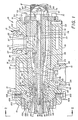
- Exemplary apparatus for the manufacture of reinforced polymeric tubing embodying the concepts of the present invention is generally indicated by the numeral 10 in Figs. 1 and 2 of the drawings.
- the primary component of apparatus 10 in the context of the present invention is an extrusion head, generally indicated by the numeral 11.
- an extrusion head 11 servicing the extrusion head 11 with a controlled supply of plasticized polymeric materials are two fragmentarily depicted extruders, generally indicated by the numerals 12 and 13, which may contain the same or different compounds and may be any of a variety of different types of extruders known in the art.
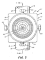
- the extrusion head 11 has as the main body member to which the extruders 12, 13 are attached, a housing, generally indicated by the numeral 14. As shown, the housing 14 is a somewhat elongate generally rectangular member. The housing 14 has a front end 15 and a spaced substantially parallel rear end 16 (Fig. 1). Disposed between and connecting the ends 15, 16 are a pair of side surfaces 17, a top surface 18 and a bottom surface 19, as best seen in Fig. 2.
- the front end 15 of housing 14 has a relatively large bore 20 for a purpose to be described hereinafter.
- the housing 14 also has a variably dimensioned throughbore 21 which extends from the rear end 16 to the bore 20 in the front end 15. As shown, the throughbore 21 has a rearward constant diameter portion 21′ and a forward tapered portion 21 ⁇ .
- the top surface of housing 14 has a recess 22 and the bottom surface 19 has a recess 23 which receive the extruders 12 and 13, respectively, and particularly the barrels 25 and 26 thereof, respectively.
- the barrels 25 and 26 are preferably substantially perpendicularly oriented relative to the housing 14 and may be aligned by virtue of pins 27 and 28 and otherwise attached to housing 14 in conventional manner.
- the screws (not shown) of the extruders 12, 13 are positioned in the barrels 25 and 26 and due in part to the recesses 22, 23 repose proximate to the top surface 18 and bottom surface 19 of housing 14 or even within the confines of these surfaces 18, 19 of the housing 14.
- the housing 14 has bores 29 and 30 within the recesses 22, 23, respectively, which communicate with the throughbore 21 of housing 14 to join it with the interior of the barrels 25, 26 of the extruders 12, 13.
- a polymeric compound and reinforcing guide assembly is positioned interiorly of the housing 14 and resides within the throughbore 21.
- the guide assembly 35 includes a forward material guide sleeve 36 which has a tapered outer circular surface 37 which resides in and interengages with the tapered portion 21 ⁇ of throughbore 21.
- Forward material guide sleeve 36 has a tapered inner surface 38 which terminates in an interior threaded portion 39 at the front end thereof.
- Extending axially forwardly of the forward material guide sleeve 36 is a material guide bushing 40.
- the material guide bushing 40 has outer threads 41 at its rear end that engage the threaded portion 39 of the guide sleeve 36 for selective attachment and detachment.
- Material guide bushing 40 has an inner surface 42 which tapers radially inwardly as it extends axially forwardly of the housing 14.
- the radially outer side of material guide bushing 40 includes a radially inwardly beveled surface 43.
- the outer polymeric material of the tubing to be manufactured employing the extrusion head 11 is supplied via the extruder 13 and the extruder barrel 26 to the bore 30 of housing 14.
- the outer polymeric material is forced into an outer polymer channel 45 which is formed in the radially outer surface of the forward material guide sleeve 36.
- the outer channel 45 is bounded outwardly by the tapered portion 21 ⁇ of the throughbore 21 and proceeds axially from approximately medially of the axial length of forward material guide sleeve 36 to the axial forward extent of throughbore 21 and to a position outwardly of the material guide bushing 40 and particularly beveled surface 43.
- the polymeric component and reinforcing material guide assembly 35 has positioned rearwardly of the forward material guide sleeve 36 a rear material guide sleeve 50 positioned within the constant diameter portion 21′ of throughbore 21 of housing 14.
- the rear material guide sleeve 50 has a rear material guide channel 51 which is a segment of an annulus formed in guide sleeve 50 and is circumferentially continuous except for a discontinuous portion in and proximate to an opening 52 which directly communicates with the bore 29 of housing 14.
- the opening 52 in guide sleeve 50 is generally radially oriented at the surface, merges into a curved portion 53, and transcends into an axially oriented mouth 54 directed radially of housing 14.
- the mouth 54 of guide sleeve 50 has internal threads 55 for selective attachment of an inner flow pipe 60 which projects axially outwardly of the mouth 54 concentrically of the bore 20 in housing 14 and substantially the length of the forward material guide sleeve 36.
- the inner flow pipe 60 is shown with threads 61 which engage the threads 55 of the guide sleeve 50.
- the forward extremity of the flow pipe 60 tapers to a point 62, such that the outer surface of the flow pipe 60 cooperates with inner surface 38 of forward material guide sleeve 36 and the inner surface 42 of guide bushing 40 to define a tapering reinforcing material guide channel 65 which communicates directly at its rear extremity with the channel 51.
- exemplary reinforcing material M introduced to rear material guide sleeve 50 in an unclosed circular configuration may be threaded forwardly around the opening 52 in the guide sleeve 50 and then further forwardly into tapering guide channel 65, wherein the reinforcing material M may assume an overlapping circular configuration with the progressively reducing diameter of channel 65 in progressing axially forwardly therein.
- the inner flow pipe 60 has a plurality of and preferably four circumferentially spaced forward adjusting screws 66 which project adjustable distances radially inwardly of the flow pipe 60.
- the rear of the flow pipe 60 or the mouth 54 of guide sleeve 50 may similarly have a plurality of and preferably four circumferentially spaced rear adjusting screws 67 which also project adjustable distances radially inwardly of the flow pipe 60 or the mouth 54 for a purpose to be hereinafter detailed.
- the polymeric compound and reinforcing material guide assembly 35 is maintained within housing 14 during actuation of extrusion head 11 by an annular end plate 70 which is attached to the rear end 16 of housing 14, as by a plurality of circumferentially spaced machine screws 71.
- the annular end plate 70 extends radially inwardly a sufficient distance such as to overlap a portion of the rear of rear material guide sleeve 50 without blocking access to the channel 51 rearwardly of the rear material guide sleeve 50.
- One or more machine screws 72 may be inserted through the annular end plate 70 into the rear material guide sleeve 50 to maintain it selectively positioned within housing 14 in the manner depicted in Fig. 1 of the drawings.
- the center mechanism 75 extends through and is supported by a bore 56 in rear material guide sleeve 50 which has threads 57 over a portion of its extent.
- the center mechanism 75 includes a center pin 76 which extends substantially the length of housing 14 and particularly from a position rearwardly of the annular end plate 70 to a position forwardly of throughbore 21 in housing 14.
- the center pin 76 is supported in a position precisely centrally of the throughbore 21 of housing 14 by an elongate cylindrical support tube 77.
- the support tube 77 is rearwardly threaded at 78 to engage the threads 57 in the bore 56 of the rear material guide sleeve 50 and projects forwardly a substantial distance into the mouth 54 of guide sleeve 50 and thence into the tapered portion 21 ⁇ of throughbore 21 which houses the forward material guide sleeve 36. It will thus be appreciated that the support tube 77 provides support to the center pin 76 over a substantial portion of its length to maintain the center pin 76 accurately and rigidly positioned within the housing 14.
- the center pin 76 is also supported in a bore 79 in a stud 80 which is threaded into the threads 57 in bore 56 of the rear material guide sleeve 50.
- a spacer 81 and a washer 82 may be threaded on the stud 80 rearwardly of the rear surface of the rear material guide sleeve 50.
- the center pin 76 has threads 83 proximate the rear extremity thereof for engagement by a nut 84 which may be tightened against the head of stud 80 to temporarily rigidly fix the center pin 76 at any desired axial position relative to the housing 14.
- center pin 76 opposite the threads 83 at the rear extremity is provided with threads 83′ for receiving an inner die 85 which is attached to the center pin by threads 86 which engage the threads 83′ for selective mounting and demounting of inner die 85 on the center pin 76.
- the inner die has radially outwardly a die face 87 and a tapering rearwardly positioned leading face 88.
- the channel 90 terminates forwardly between the point 62 of inner flow pipe 60 and the leading face 88 which proceeds to die face 87 of the inner die 85. It will thus be appreciated that axial adjustment of the center pin 76 as effected by altering the position of nut 84 on threads 83′ will control the position of the point 62 of inner flow pipe 60 to establish the desired axial thickness of the inner polymer compound of the tubing T being extruded. Significantly, it is to be noted that this thickness adjustment of the inner polymer compound can be effected strictly by adjustment of nut 84 which is located rearwardly of the housing 14. Due to this advantageous arrangement, it is therefore possible to effect desired adjustments in this respect without discontinuing operation of the extruders 12, 13 or without clearing away tubing T which may be located forwardly of the inner die 85.
- the adjusting screws 66 and 67 in inner flow pipe 60 and mouth 54 of guide sleeve 50 may be appropriately adjusted relative to center pin 76 and support tube 77 such as to adjust for absolute circumstantial concentricity of the inner polymeric channel 90.
- the resultant tubing T has an inner polymeric compound which is of uniform thickness about the entire circumference thereof.
- the center pin 76 is advantageously provided with a bore 91 which extends the full length thereof, i.e., from the end having inner die 85 to the rear end having the threads 83. With the forward opening of bore 91 within the tubing T, it is possible to supply a fluid such as compressed air from the rearward extremity of center pin 76 interiorly of the tubing T being emitted around the inner die 85 such as to maintain the tubing T in its extruded configuration after departing the die area or if desired subsequently while the tubing T may undergo a curing process.
- a fluid such as compressed air
- the axially outer side of point 62 of inner flow pipe 60 defines the termination of reinforcing material guide channel 65 wherein the reinforcing material is emitted to be positioned radially outwardly on the inner polymeric compound as it engages the die face 87 of inner die 85.
- the guide bushing 40 may extend slightly axially forwardly of the point 62 of inner flow pipe 60, such that the reinforcing material M may be compressed against the inner surface 42 of material guide bushing 40 for a short axial distance after the reinforcing material M and the inner polymeric compound from channel 90 are joined at the axial extremity of point 62.
- the outer polymeric compound of the tubing T is supplied through extruder 13, bore 30 and outer polymer channel 45.
- the disposition of the outer polymeric material is controlled radially inwardly thereof by the beveled surface 43 of the guide bushing 40.
- the outer polymeric compound is controlled radially outwardly thereof by an outer die assembly, generally indicated by the numeral 100.
- the outer die assembly 100 consists of an outer die 101 which has a die face 101′ defining the outer surface of the tubing T and particularly the outer polymeric compound.
- the outer die 101 is mounted on a die holder 102 which, with the other components of outer die assembly 100, is positioned in the bore 20 in the front end 15 of housing 14.
- the concentricity of the outer die 101 of outer die assembly 100 relative to the inner die 85 and the material guide bushing 40 is established by a plurality of centering studs 103 which extend through threads 104 in the housing 14 and abut the radially outer surface of the die holder 102.
- centering studs 103 which may be appropriately radially adjusted to position die holder 102 and thence die 101 such that the die face 101′ is positioned to produce an outer polymeric compound thickness of the tubing T which is radially uniform circumferentially about tubing T. It will be appreciated that this adjustment can be readily made even during operation of the extruder head 11.
- an outer ring nut 105 which engages threads 106 in the housing 14 operates as a jam nut to lock the die holder 102 in fixed position relative to the housing 14. It will thus be appreciated that further adjustment can be effected merely by loosening the outer ring nut 105, effecting any necessary adjustment to appropriate studs 103 of the entire group of centering studs 103, followed by a retightening of the outer ring nut 105.
- the axial position of the outer die 101 relative to guide bushing 40 controls the radial thickness of the outer polymeric compound of the tubing T.
- the outer die holder 102 carrying the outer die 101 is axially positioned relative to the die holder 102 and the other die component by virtue of an inner ring nut 110 which axially abuts the outer die 101 and has threads 111 which engage with threads 112 located on the die holder 102.
- the threaded adjustment of the inner ring nut 110 effects the desired axial positioning of the outer die 101.
Landscapes
- Engineering & Computer Science (AREA)
- Mechanical Engineering (AREA)
- Manufacturing & Machinery (AREA)
- Extrusion Moulding Of Plastics Or The Like (AREA)
- Reinforced Plastic Materials (AREA)
- Moulding By Coating Moulds (AREA)
- Rigid Pipes And Flexible Pipes (AREA)
Applications Claiming Priority (2)
| Application Number | Priority Date | Filing Date | Title |
|---|---|---|---|
| US359851 | 1989-05-31 | ||
| US07/359,851 US4946364A (en) | 1989-05-31 | 1989-05-31 | Apparatus for manufacturing reinforced polymeric tubing |
Publications (3)
| Publication Number | Publication Date |
|---|---|
| EP0400339A2 true EP0400339A2 (de) | 1990-12-05 |
| EP0400339A3 EP0400339A3 (de) | 1991-01-16 |
| EP0400339B1 EP0400339B1 (de) | 1994-06-15 |
Family
ID=23415554
Family Applications (1)
| Application Number | Title | Priority Date | Filing Date |
|---|---|---|---|
| EP90108199A Expired - Lifetime EP0400339B1 (de) | 1989-05-31 | 1990-04-29 | Vorrichtung zur Herstellung verstärkter Polymerrohre |
Country Status (7)
| Country | Link |
|---|---|
| US (1) | US4946364A (de) |
| EP (1) | EP0400339B1 (de) |
| JP (1) | JP2902450B2 (de) |
| AT (1) | ATE107220T1 (de) |
| CA (1) | CA2017171C (de) |
| DE (1) | DE69009859T2 (de) |
| ES (1) | ES2057250T3 (de) |
Cited By (2)
| Publication number | Priority date | Publication date | Assignee | Title |
|---|---|---|---|---|
| DE4111228A1 (de) * | 1991-04-08 | 1992-10-15 | Wilhelm Hegler | Vorrichtung zur herstellung von kunststoff-rohren |
| EP1129838A2 (de) * | 2000-02-21 | 2001-09-05 | Fischer-W. Müller Blasformtechnik GmbH | Vorrichtung zum Herstellen von hohlkörperförmigen Artikeln aus thermoplastischem Kunststoff durch Saugblasen |
Families Citing this family (11)
| Publication number | Priority date | Publication date | Assignee | Title |
|---|---|---|---|---|
| CA2039500C (en) * | 1990-07-18 | 1994-02-15 | Takahisa Kawaguchi | Apparatus for forming bent portion of pipe in apparatus for making bent pipe |
| US5062782A (en) * | 1990-07-24 | 1991-11-05 | Bridgestone/Firestone, Inc. | Coextrusion apparatus for varying the inner and/or outer profile of a tubular extrudate |
| US5108682A (en) * | 1990-07-24 | 1992-04-28 | Bridgestone/Firestone, Inc. | Coextrusion apparatus and method using an elastic die for varying the outer profile of a tubular extrudate |
| US5069850A (en) * | 1990-07-24 | 1991-12-03 | Bridgestone/Firestone, Inc. | Coextrusion apparatus and method using a rigid die for varying the outer profile of a tubular extrudate |
| US5128084A (en) * | 1990-07-24 | 1992-07-07 | Bridgestone Firestone Inc | Coextrusion apparatus and method for varying the inner profile of a tubular extrudate |
| KR100433310B1 (ko) * | 2001-06-29 | 2004-05-31 | 강봉석 | 교환 구가 장착된 열 교환 관 압출 장치 |
| US20070190201A1 (en) * | 2006-02-13 | 2007-08-16 | Irwin Jere E | Extruder die assembly, extruder, and method |
| DE102014103521B3 (de) * | 2014-03-14 | 2015-05-07 | Kraussmaffei Berstorff Gmbh | Schlauchspritzkopf |
| CN103895207B (zh) * | 2014-04-04 | 2016-01-06 | 苏州同大机械有限公司 | 一种纳米叠层复合挤出设备 |
| ITUA20162984A1 (it) * | 2016-04-28 | 2017-10-28 | Friul Filiere Spa | Testa di estrusione di tubi |
| CA3095514A1 (en) * | 2019-10-09 | 2021-04-09 | Davis-Standard, Llc | A polymeric tube forming apparatus with a multi-dimensional control system |
Citations (5)
| Publication number | Priority date | Publication date | Assignee | Title |
|---|---|---|---|---|
| GB977208A (de) * | 1900-01-01 | |||
| GB1342178A (en) * | 1970-12-15 | 1973-12-25 | Tanaka K | Apparatus for manufacturing extruded reinforced synthetic resin tubes |
| GB1355040A (en) * | 1970-05-21 | 1974-05-30 | Creators Ltd | Apparatus for and method of manufacturing reinforced tubes of plastics or elastomeric material |
| US4161379A (en) * | 1977-07-21 | 1979-07-17 | The Johnson Rubber Company | Apparatus for producing reinforced hose |
| US4362488A (en) * | 1980-03-12 | 1982-12-07 | Casals Ramon R | Extruder for continuous manufacture of reinforced tubing, especially hose |
Family Cites Families (21)
| Publication number | Priority date | Publication date | Assignee | Title |
|---|---|---|---|---|
| US2760230A (en) * | 1955-07-05 | 1956-08-28 | Jurian W Van Riper | Plastic material extrusion head |
| US2874411A (en) * | 1956-08-10 | 1959-02-24 | Nat Standard Co | Apparatus for coating and impregnating tubular fabrics |
| US2928123A (en) * | 1958-09-19 | 1960-03-15 | Justin H Ramsey | Plastic material extrusion head |
| US3058493A (en) * | 1959-02-11 | 1962-10-16 | Porter Co Inc H K | Flexible reinforced corrugated hose |
| US3159877A (en) * | 1962-11-05 | 1964-12-08 | Plastus S A Sa | Machines for the extrusion of casings, conduits or shaped sectional members of reinforced material |
| US3405426A (en) * | 1964-09-28 | 1968-10-15 | Dow Chemical Co | Apparatus for the preparation of reinforced tubes |
| GB1144046A (en) * | 1966-02-05 | 1969-03-05 | Induplas S P A | Method and apparatus for the manufacturing of tubes of plastics material |
| US3365750A (en) * | 1966-07-11 | 1968-01-30 | Dow Chemical Co | Extrusion die |
| US3538547A (en) * | 1968-04-26 | 1970-11-10 | Gen Electric | Extruder head for dual extrusion |
| NL166426C (nl) * | 1968-09-20 | 1900-01-01 | Schiesser Ag | Extrusiemondstuk voor de vervaardiging van een gewa- pende slang uit thermoplastische kunststof. |
| US3773449A (en) * | 1970-06-05 | 1973-11-20 | Du Pont | Apparatus for producing continuous round jacketed lightguides |
| US3856447A (en) * | 1970-06-16 | 1974-12-24 | Schiesser Ag | Extrusion head for the manufacture of hoses formed of plastic masses and containing reinforcement inserts |
| US3694131A (en) * | 1971-03-25 | 1972-09-26 | Dart Ind Inc | Die for impregnating and coating filamentary material |
| DE2332518A1 (de) * | 1973-06-22 | 1975-01-23 | Siemens Ag | Spritzkopf |
| US4081232A (en) * | 1977-02-08 | 1978-03-28 | The Anaconda Company | Fixed center tooling for an extruder that provides for concentric layers of coating material |
| FR2515411A1 (fr) * | 1981-10-28 | 1983-04-29 | Telecommunications Sa | Procede et dispositif de fabrication d'un jonc a rainures helicoidales pour cable a fibres optiques et le jonc obtenu selon le procede |
| US4465449A (en) * | 1982-12-06 | 1984-08-14 | Borg-Warner Chemicals, Inc. | Coextrusion feedblock for making lightweight, rigid thermoplastic pipe |
| US4585407A (en) * | 1983-10-03 | 1986-04-29 | Pirelli Cable Corporation | Guide for electric cable insulation extrusion head |
| SU1319084A1 (ru) * | 1984-01-05 | 1987-06-23 | Томский Научно-Исследовательский,Проектно-Конструкторский И Технологический Кабельный Институт | Экструзионна головка |
| US4657496A (en) * | 1984-06-04 | 1987-04-14 | Gifu Husky Co., Ltd. | Hot-runner mold for injection molding |
| DE3617652A1 (de) * | 1986-05-26 | 1987-12-03 | Troester Maschf Paul | Extruderanlage zum ummanteln eines strangfoermigen produktes, insbesondere eines kabels |
-
1989
- 1989-05-31 US US07/359,851 patent/US4946364A/en not_active Expired - Fee Related
-
1990
- 1990-04-29 DE DE69009859T patent/DE69009859T2/de not_active Expired - Fee Related
- 1990-04-29 EP EP90108199A patent/EP0400339B1/de not_active Expired - Lifetime
- 1990-04-29 AT AT90108199T patent/ATE107220T1/de not_active IP Right Cessation
- 1990-04-29 ES ES90108199T patent/ES2057250T3/es not_active Expired - Lifetime
- 1990-05-18 CA CA002017171A patent/CA2017171C/en not_active Expired - Fee Related
- 1990-05-30 JP JP2141197A patent/JP2902450B2/ja not_active Expired - Lifetime
Patent Citations (5)
| Publication number | Priority date | Publication date | Assignee | Title |
|---|---|---|---|---|
| GB977208A (de) * | 1900-01-01 | |||
| GB1355040A (en) * | 1970-05-21 | 1974-05-30 | Creators Ltd | Apparatus for and method of manufacturing reinforced tubes of plastics or elastomeric material |
| GB1342178A (en) * | 1970-12-15 | 1973-12-25 | Tanaka K | Apparatus for manufacturing extruded reinforced synthetic resin tubes |
| US4161379A (en) * | 1977-07-21 | 1979-07-17 | The Johnson Rubber Company | Apparatus for producing reinforced hose |
| US4362488A (en) * | 1980-03-12 | 1982-12-07 | Casals Ramon R | Extruder for continuous manufacture of reinforced tubing, especially hose |
Cited By (4)
| Publication number | Priority date | Publication date | Assignee | Title |
|---|---|---|---|---|
| DE4111228A1 (de) * | 1991-04-08 | 1992-10-15 | Wilhelm Hegler | Vorrichtung zur herstellung von kunststoff-rohren |
| US5346384A (en) * | 1991-04-08 | 1994-09-13 | Wilhelm Hegler | Apparatus for the production of plastic pipes |
| EP1129838A2 (de) * | 2000-02-21 | 2001-09-05 | Fischer-W. Müller Blasformtechnik GmbH | Vorrichtung zum Herstellen von hohlkörperförmigen Artikeln aus thermoplastischem Kunststoff durch Saugblasen |
| EP1129838A3 (de) * | 2000-02-21 | 2003-10-22 | SIG Kautex GmbH & Co. KG | Vorrichtung zum Herstellen von hohlkörperförmigen Artikeln aus thermoplastischem Kunststoff durch Saugblasen |
Also Published As
| Publication number | Publication date |
|---|---|
| CA2017171A1 (en) | 1990-11-30 |
| JP2902450B2 (ja) | 1999-06-07 |
| JPH0396315A (ja) | 1991-04-22 |
| DE69009859D1 (de) | 1994-07-21 |
| CA2017171C (en) | 1994-07-05 |
| US4946364A (en) | 1990-08-07 |
| EP0400339B1 (de) | 1994-06-15 |
| DE69009859T2 (de) | 1995-02-02 |
| ATE107220T1 (de) | 1994-07-15 |
| EP0400339A3 (de) | 1991-01-16 |
| ES2057250T3 (es) | 1994-10-16 |
Similar Documents
| Publication | Publication Date | Title |
|---|---|---|
| US4946364A (en) | Apparatus for manufacturing reinforced polymeric tubing | |
| EP0239046B1 (de) | Extruderdüse für aussen geripptes Kunststoffrohr | |
| US7335010B2 (en) | Device for producing rigid plastic pipes | |
| US4161379A (en) | Apparatus for producing reinforced hose | |
| CA1203960A (en) | Apparatus and method for controlling internal size of an extruded hose | |
| JPS6325015A (ja) | 押出成形機 | |
| EP0472864B1 (de) | Coextrusionsvorrichtung und -verfahren unter Verwendung einer elastischen Düse zum Verändern des Aussenprofils eines rohrförmigen Strangpresslings | |
| CN101166617B (zh) | 挤压聚合材料的方法及所用的挤压头 | |
| EP0468261B1 (de) | Koextrusionsmaschine und Verfahren zum Verändern des Innenprofils eines rohrförmigen Extrudats | |
| JP3157858B2 (ja) | 筒状押出し体の外側輪郭の変更用の剛性型を使用した共押出し装置及び方法 | |
| JPH04250019A (ja) | 共押出し装置 | |
| US3859017A (en) | Extrusion of sheath onto elongated support using decompression zones | |
| US8956559B2 (en) | Tubular member extrusion method and tubular member extrusion apparatus | |
| US2614056A (en) | Method of and apparatus for forming tire bands and band so formed | |
| US3359357A (en) | Process for coating continuous flexible tubing | |
| US5908642A (en) | Extrusion head for plastics extruder | |
| US20060121154A1 (en) | Laser device for alignment of a nozzle tip within injection molding and extrusion equipment | |
| US4118167A (en) | Coextrusion die | |
| US10583596B2 (en) | Injection head for an apparatus for the production of a twin-wall pipe | |
| US4097564A (en) | Method of coating flexible sleeving | |
| JPH1044214A (ja) | スパイラルホース製造装置 | |
| KR101274676B1 (ko) | 합성수지재 원통형 파이프의 패킹 홈 성형장치 및 그 방법 | |
| JP7374138B2 (ja) | 固定プロファイルを有する押出装置 | |
| CN117549532A (zh) | 挤出机用挤出机头、挤出设备及其更换方法 | |
| JPH0732372A (ja) | 離型剤塗布機構 |
Legal Events
| Date | Code | Title | Description |
|---|---|---|---|
| PUAI | Public reference made under article 153(3) epc to a published international application that has entered the european phase |
Free format text: ORIGINAL CODE: 0009012 |
|
| PUAL | Search report despatched |
Free format text: ORIGINAL CODE: 0009013 |
|
| AK | Designated contracting states |
Kind code of ref document: A2 Designated state(s): AT BE CH DE DK ES FR GB IT LI LU NL SE |
|
| AK | Designated contracting states |
Kind code of ref document: A3 Designated state(s): AT BE CH DE DK ES FR GB IT LI LU NL SE |
|
| 17P | Request for examination filed |
Effective date: 19910714 |
|
| 17Q | First examination report despatched |
Effective date: 19921001 |
|
| GRAA | (expected) grant |
Free format text: ORIGINAL CODE: 0009210 |
|
| AK | Designated contracting states |
Kind code of ref document: B1 Designated state(s): AT BE CH DE DK ES FR GB IT LI LU NL SE |
|
| PG25 | Lapsed in a contracting state [announced via postgrant information from national office to epo] |
Ref country code: NL Effective date: 19940615 Ref country code: LI Effective date: 19940615 Ref country code: DK Effective date: 19940615 Ref country code: CH Effective date: 19940615 Ref country code: BE Effective date: 19940615 Ref country code: AT Effective date: 19940615 |
|
| REF | Corresponds to: |
Ref document number: 107220 Country of ref document: AT Date of ref document: 19940715 Kind code of ref document: T |
|
| REF | Corresponds to: |
Ref document number: 69009859 Country of ref document: DE Date of ref document: 19940721 |
|
| ET | Fr: translation filed | ||
| ITF | It: translation for a ep patent filed |
Owner name: BARZANO' E ZANARDO ROMA S.P.A. |
|
| PG25 | Lapsed in a contracting state [announced via postgrant information from national office to epo] |
Ref country code: SE Effective date: 19940915 |
|
| REG | Reference to a national code |
Ref country code: CH Ref legal event code: PL |
|
| REG | Reference to a national code |
Ref country code: ES Ref legal event code: FG2A Ref document number: 2057250 Country of ref document: ES Kind code of ref document: T3 |
|
| NLV1 | Nl: lapsed or annulled due to failure to fulfill the requirements of art. 29p and 29m of the patents act | ||
| PLBE | No opposition filed within time limit |
Free format text: ORIGINAL CODE: 0009261 |
|
| STAA | Information on the status of an ep patent application or granted ep patent |
Free format text: STATUS: NO OPPOSITION FILED WITHIN TIME LIMIT |
|
| PG25 | Lapsed in a contracting state [announced via postgrant information from national office to epo] |
Ref country code: LU Free format text: LAPSE BECAUSE OF NON-PAYMENT OF DUE FEES Effective date: 19950430 |
|
| 26N | No opposition filed | ||
| REG | Reference to a national code |
Ref country code: GB Ref legal event code: 732E |
|
| REG | Reference to a national code |
Ref country code: FR Ref legal event code: TP |
|
| REG | Reference to a national code |
Ref country code: ES Ref legal event code: PC2A |
|
| PGFP | Annual fee paid to national office [announced via postgrant information from national office to epo] |
Ref country code: ES Payment date: 20000407 Year of fee payment: 11 |
|
| PGFP | Annual fee paid to national office [announced via postgrant information from national office to epo] |
Ref country code: GB Payment date: 20000426 Year of fee payment: 11 |
|
| PGFP | Annual fee paid to national office [announced via postgrant information from national office to epo] |
Ref country code: FR Payment date: 20000427 Year of fee payment: 11 |
|
| PG25 | Lapsed in a contracting state [announced via postgrant information from national office to epo] |
Ref country code: GB Free format text: LAPSE BECAUSE OF NON-PAYMENT OF DUE FEES Effective date: 20010429 |
|
| PG25 | Lapsed in a contracting state [announced via postgrant information from national office to epo] |
Ref country code: FR Free format text: THE PATENT HAS BEEN ANNULLED BY A DECISION OF A NATIONAL AUTHORITY Effective date: 20010430 Ref country code: ES Free format text: LAPSE BECAUSE OF NON-PAYMENT OF DUE FEES Effective date: 20010430 |
|
| GBPC | Gb: european patent ceased through non-payment of renewal fee |
Effective date: 20010429 |
|
| REG | Reference to a national code |
Ref country code: FR Ref legal event code: ST |
|
| REG | Reference to a national code |
Ref country code: ES Ref legal event code: FD2A Effective date: 20030303 |
|
| PG25 | Lapsed in a contracting state [announced via postgrant information from national office to epo] |
Ref country code: IT Free format text: LAPSE BECAUSE OF NON-PAYMENT OF DUE FEES;WARNING: LAPSES OF ITALIAN PATENTS WITH EFFECTIVE DATE BEFORE 2007 MAY HAVE OCCURRED AT ANY TIME BEFORE 2007. THE CORRECT EFFECTIVE DATE MAY BE DIFFERENT FROM THE ONE RECORDED. Effective date: 20050429 |
|
| PGFP | Annual fee paid to national office [announced via postgrant information from national office to epo] |
Ref country code: DE Payment date: 20060419 Year of fee payment: 17 |
|
| PG25 | Lapsed in a contracting state [announced via postgrant information from national office to epo] |
Ref country code: DE Free format text: LAPSE BECAUSE OF NON-PAYMENT OF DUE FEES Effective date: 20071101 |