EP0399894A1 - Seating furniture made of plastics - Google Patents
Seating furniture made of plastics Download PDFInfo
- Publication number
- EP0399894A1 EP0399894A1 EP90401357A EP90401357A EP0399894A1 EP 0399894 A1 EP0399894 A1 EP 0399894A1 EP 90401357 A EP90401357 A EP 90401357A EP 90401357 A EP90401357 A EP 90401357A EP 0399894 A1 EP0399894 A1 EP 0399894A1
- Authority
- EP
- European Patent Office
- Prior art keywords
- stud
- assembly
- furniture according
- studs
- component
- Prior art date
- Legal status (The legal status is an assumption and is not a legal conclusion. Google has not performed a legal analysis and makes no representation as to the accuracy of the status listed.)
- Withdrawn
Links
Images


Classifications
-
- A—HUMAN NECESSITIES
- A47—FURNITURE; DOMESTIC ARTICLES OR APPLIANCES; COFFEE MILLS; SPICE MILLS; SUCTION CLEANERS IN GENERAL
- A47C—CHAIRS; SOFAS; BEDS
- A47C4/00—Foldable, collapsible or dismountable chairs
- A47C4/02—Dismountable chairs
-
- A—HUMAN NECESSITIES
- A47—FURNITURE; DOMESTIC ARTICLES OR APPLIANCES; COFFEE MILLS; SPICE MILLS; SUCTION CLEANERS IN GENERAL
- A47C—CHAIRS; SOFAS; BEDS
- A47C11/00—Benches not otherwise provided for
- A47C11/005—Benches not otherwise provided for having multiple separate seats
-
- A—HUMAN NECESSITIES
- A47—FURNITURE; DOMESTIC ARTICLES OR APPLIANCES; COFFEE MILLS; SPICE MILLS; SUCTION CLEANERS IN GENERAL
- A47C—CHAIRS; SOFAS; BEDS
- A47C4/00—Foldable, collapsible or dismountable chairs
- A47C4/02—Dismountable chairs
- A47C4/03—Non-upholstered chairs, e.g. metal, plastic or wooden chairs
-
- A—HUMAN NECESSITIES
- A47—FURNITURE; DOMESTIC ARTICLES OR APPLIANCES; COFFEE MILLS; SPICE MILLS; SUCTION CLEANERS IN GENERAL
- A47C—CHAIRS; SOFAS; BEDS
- A47C5/00—Chairs of special materials
- A47C5/12—Chairs of special materials of plastics, with or without reinforcement
Definitions
- the present invention relates to a plastic furniture for sitting of the type of those which have two sides and at least one shell assembled and fixed together.
- the means for assembling and fixing these known pieces of furniture are constituted by pins projecting perpendicularly to the internal face of the sides and penetrating horizontally into holes in the shell which open onto the edge thereof, this interlocking being completed by a fixing carried out from the inside of the hull by means of a screw.
- This connection mode has the disadvantage of not being rigid enough and of taking play in use so that the furniture becomes rickety very quickly.
- the mold provided for the manufacture of the shell is relatively complicated, since it must include moving parts to provide the holes in the edges.
- the assembly is also awkward because the screws are difficult to access and maneuver.
- the shell cannot be used independently of the sidewalls as a fireside chair, without the addition of moldings on the edges to hide the holes.
- the object of the present invention is to remedy these drawbacks, by proposing a particular connection method by which the rigidity of the piece of furniture is considerably improved between the shell and the sidewall, as well as between two adjoining shells without the addition of bars; thanks to which also the manufacturing molds are simplified, the fixing screws are easily accessible, the shells have a finished appearance and the piece of furniture is truly modular in the sense that the same modules are suitable whatever the length of this piece of furniture.
- connection of two components (sidewalls, shells, etc.) to one another is ensured, at the front as at the rear, by an assembly stud forming one body components, extending in lateral projection to point upwards and cooperating by interlocking with a mounting housing of the other component which opens downwards for the penetration, by sliding in a substantially vertical plane, of the front and rear studs assembly, a screw passing through each stud from bottom to top and screwing into a hole of said other component.
- the front and rear housing for mounting this shell have walls inclined substantially in the direction of release to allow the nesting in this direction of the mating assembly pads forming a body with the component to be attached.
- the anterior and posterior assembly pads have come from molding on each flank and protrude from the inner lateral face thereof.
- each assembly stud protrudes from a molded part also projecting, in a perpendicular direction, a positioning stud intended to be fitted into a housing for receiving the component to be fitted and to be fixed to it by means of a screw, these studs being oriented relative to each other so that, the two components to be joined being suitably arranged, the assembly stud is located opposite the corresponding mounting housing.
- twin assembly pads form a body with each of two posterior and anterior intermediate feet, these twin pads being intended to be nested and fixed in the mounting housings of two contiguous shells.
- each assembly stud is connected to its support (sidewall or insert or intermediate leg) by a shoulder intended to bear against the component delimiting the mounting housing conjugated to this stud; each positioning pad is connected to the insert by a shoulder intended to rest on the component delimiting the reception housing conjugated to this pad; the studs have sloping faces to get stuck in their housings.
- the furniture for sitting is an assembly of several modular plastic components injection molded.
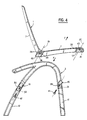
- the armchair (FIG. 1) has a shell 1 joined with two symmetrical sides 2 and 3.
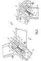
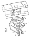
- the bench seat (FIGS. 2 and 3) has two identical shells 1 joined together by a rear intermediate leg 4 and a front intermediate leg 5, as well as with two symmetrical sides 2 and 3.
- the hull 1 is monolithic and has members 6, 7 which are lateral profiles between which extend substantially horizontal slats 8 to form the seat, as well as cross members 9 connected by rising slats 10 to form the backrest.
- the sides 2 and 3 have the shape of an arch, the branches of which constitute a right front foot 11 and a curved rear foot 12 connected to each other, above the level of the seat, by a rounded 13 extended towards the rear by an armrest 14.
- the sides 2 and 3 can review any other form appropriate to the chosen aesthetic, as long as the connecting means recommended in the following, can be implemented.
- each shell 1 with a side wall 2 or 3 is ensured by means of assembly pads 15 and 16 cooperating with mounting housings 17 and 18.
- the assembly pads 15 and 16 are integral with the feet 11 and 12 respectively, being spaced therefrom and extending pointed upward projecting from their internal face.
- the mounting housings 17 and 18 are delimited by partitions of the corresponding frame 6 or 7 of the hull.
- the axes 19 and 20 of the housings 17 and 18 are parallel to the direction F of demoulding of the shell, that is to say to the direction in which the two parts of the mold are spaced from each other to release said shell from the imprint bounded by said parts.
- the longitudinal partitions 21, 22 and 23, 24 of the housings 17 and 18 which are then substantially parallel (to the demoulding clearance or to the near wedge slope which are mentioned in the following) in the direction F, are demolded very easily.
- the assembly pads 15 and 16 are U-shaped profiles whose section can be written in a square for the rear legs 12 and in a rectangle for the front legs 11, a section which corresponds substantially to that of the housings. 17 and 18.
- the longitudinal partitions 21 to 24 are therefore in plan contact parallel to the axes 19, 20 and perpendicular to the plane defined by these.
- a slope slightly greater than the demoulding draft may be provided on these partitions which, therefore, by cooperating with the wings of the studs 15, 16 with a conjugate slope, generate their jamming.
- the partitions 21 to 24 are situated in such a way that only two of these partitions can bear against the wings of the studs 15 and 16 when these studs are completely embossed in the housings 17 and 18, a slight play then appearing between the two other partitions and said studs.
- the housings are also delimited by antero posterior partitions 25 to 28 extending parallel to the plane defined by the axes 19 and 20. They are sloping and separated so as to all bear against the studs 15 and 16.
- the studs 15 and 16 have come from molding with the sides.
- the mold must then include moving parts to allow demolding.
- the studs 15 and 16 protrude from parts molded 29 and 30 respectively. These parts also comprise projecting, in a perpendicular direction, positioning pads 31 and 32. These have a tubular shape of rectangular section complementary to that of receiving housings 33 and 34 respectively delimited by the corresponding flank 2 or 3. These housings are very easy to obtain, given that the sides can be removed from the mold perpendicularly to their lateral faces and that the housings can be removed from the mold in the same direction, the mold half simply having fixed projections at their location.
- the pads 15 and 31 are oriented relative to each other so that, taking into account the location of the receiving housing 33 in which the conjugate positioning pad 31 must be fitted, the assembly pad 15 is perfectly aligned with the mounting housing 17.
- the studs 16 and 32 are oriented to take account of the locations of the housings 34 and 18.
- parts 29 and 30 are integral with the sides 2 and 3, the parts of one side being symmetrical with the parts of the other side as are besides the flanks relative to each other.
- these sides 2 and 3 have projecting assembly pads 15 and 16 suitably oriented.
- the assembly pads 15 and 16 of each of the sides 1 and 2 are fitted into the mounting housings 17 and 18 of the corresponding frame 6 or 7 of a shell 1. Then, screws 41 and 42 pass through holes 43 and 44 formed in the bottoms of the assembly pads 15 and 16 and are screwed into sleeves 45 and 46 of the shell projecting in the housings 17 and 18.
- the assembly pads 15 and 16 are connected to parts 29 and 30 or to said flanks when these form a molding body with these studs, by shoulders 47 and 48 (FIGS. 8 and 9) ensuring a wide reach against the frames 6 and 7 of the hull and thus improving the embedding .
- the same means can be used to improve the fixing of the parts 29 and 30 on the sides 2 and 3 and, for this purpose, the positioning pads 31 and 32 are connected to said parts 29 and 30 by shoulders 49 and 50 ( Figures 8 and 9) ensuring a wide range against the sides and thus improving the embedding.
- the mounting slots 17 and 18 of the frame 6 of the right hull in Figure 2 and those of the frame 7 of the left hull are used to receive two assembly pads 16 forming a body with a marquee 51 surmounting the foot 4 and respectively two assembly pads 15 forming a body with a marquee 52 surmounting the foot 5, fixing screws being put in place as before.
Abstract
Description
La présente invention concerne un meuble en matière plastique pour s'asseoir du type de ceux qui comportent deux flancs et au moins une coque assemblés et fixés entre eux.The present invention relates to a plastic furniture for sitting of the type of those which have two sides and at least one shell assembled and fixed together.
Les moyens d'assemblage et de fixation de ces meubles connus sont constitués par des tourillons faisant saillie perpendiculairement à la face interne des flancs et pénétrant horizontalement dans des trous de la coque qui débouchent sur le chant de celle-ci, cet emboîtement étant complété par une fixation exécutée par l'intérieur de la coque au moyen d'une vis.The means for assembling and fixing these known pieces of furniture are constituted by pins projecting perpendicularly to the internal face of the sides and penetrating horizontally into holes in the shell which open onto the edge thereof, this interlocking being completed by a fixing carried out from the inside of the hull by means of a screw.
Ce mode de liaison présente l'inconvénient de ne pas être suffisamment rigide et de prendre du jeu à l'usage de sorte que le meuble devient branlant très rapidement.This connection mode has the disadvantage of not being rigid enough and of taking play in use so that the furniture becomes rickety very quickly.
Par ailleurs, il ne convient pas pour réunir deux coques contigues lorsque le meuble est une banquette. Dès lors, il est nécessaire de prévoir des barres longitudinales complétant la structure, barres qui alourdissent le meuble, augmentent son prix de revient et nuisent à l'esthétique.Furthermore, it is not suitable for joining two adjoining shells when the piece of furniture is a bench seat. Therefore, it is necessary to provide longitudinal bars completing the structure, bars which weigh down the piece of furniture, increase its cost price and detract from the aesthetics.
De plus, le moule prévu pour la fabrication de la coque est relativement compliqué, étant donné qu'il doit comporter des pièces mobiles pour ménager les trous dans les chants.In addition, the mold provided for the manufacture of the shell is relatively complicated, since it must include moving parts to provide the holes in the edges.
Le montage est en outre malcommode car les vis sont d'un accès et d'une manoeuvre difficiles.The assembly is also awkward because the screws are difficult to access and maneuver.
Enfin, la coque ne peut pas être utilisée indépendamment des flancs comme chauffeuse, sans l'adjonction de moulures sur les chants pour masquer les trous.Finally, the shell cannot be used independently of the sidewalls as a fireside chair, without the addition of moldings on the edges to hide the holes.
La présente invention a pour but de remédier à ces inconvénients, en proposent un mode de liaison particulier grâce auquel la rigidité du meuble se trouve considérablement améliorée entre coque et flanc, ainsi qu'entre deux coques contigues sans l'adjonction de barres; grâce auquel également les moules de fabrication se trouvent simplifiés, les vis de fixation sont facilement accessibles, les coques ont un aspect fini et le meuble est véritablement modulaire en ce sens que les mêmes modules conviennent quelle que soit la longueur de ce meuble.The object of the present invention is to remedy these drawbacks, by proposing a particular connection method by which the rigidity of the piece of furniture is considerably improved between the shell and the sidewall, as well as between two adjoining shells without the addition of bars; thanks to which also the manufacturing molds are simplified, the fixing screws are easily accessible, the shells have a finished appearance and the piece of furniture is truly modular in the sense that the same modules are suitable whatever the length of this piece of furniture.
Dans ce but et conformément à l'invention, la liaison de deux composants (flancs, coques...) entre eux est assurée, à l'avant comme à l'arrière, par un plot d'assemblage faisant corps avec l'un des composants, s'étendant en saillie latérale pour pointer vers le haut et coopérant par emboîtement avec un logement de montage de l'autre composant qui débouche vers le bas pour la pénétration, par coulissement dans un plan sensiblement vertical, des plots antérieur et postérieur d'assemblage, une vis traversant chaque plot de bas en haut et se vissant dans un trou dudit autre composant.For this purpose and in accordance with the invention, the connection of two components (sidewalls, shells, etc.) to one another is ensured, at the front as at the rear, by an assembly stud forming one body components, extending in lateral projection to point upwards and cooperating by interlocking with a mounting housing of the other component which opens downwards for the penetration, by sliding in a substantially vertical plane, of the front and rear studs assembly, a screw passing through each stud from bottom to top and screwing into a hole of said other component.
Avantageusement, si l'on considère la direction de démoulage de la ou de chaque coque qui s'étend obliquement par rapport à l'assise et au dossier, les logements antérieurs et postérieurs de montage de cette coque présentent des parois inclinées sensiblement dans la direction de démoulage pour permettre l'emboîtement dans cette direction des plots d'assemblage conjugués faisant corps avec le composent à rapporter.Advantageously, if we consider the direction of demoulding of the or each shell which extends obliquely with respect to the seat and the backrest, the front and rear housing for mounting this shell have walls inclined substantially in the direction of release to allow the nesting in this direction of the mating assembly pads forming a body with the component to be attached.
Suivant une première forme de réalisation, les plots antérieur et postérieur d'assemblage sont venus de moulage sur chaque flanc et font saillie sur la face latérale intérieure de celui-ci.According to a first embodiment, the anterior and posterior assembly pads have come from molding on each flank and protrude from the inner lateral face thereof.
Suivant une deuxième forme de réalisation, chaque plot d'assemblage fait saillie sur une pièce moulée comportant également en saillie, dans une direction perpendiculaire, un plot de positionnement destiné à être emboîté dans un logement de réception du composent à équiper et à y être fixé au moyen d'une vis, ces plots étant orientés l'un par rapport à l'autre de façon que, les deux composants à réunir étant convenablement disposés, le plot d'assemblage soit situé en regard du logement de montage correspondant.According to a second embodiment, each assembly stud protrudes from a molded part also projecting, in a perpendicular direction, a positioning stud intended to be fitted into a housing for receiving the component to be fitted and to be fixed to it by means of a screw, these studs being oriented relative to each other so that, the two components to be joined being suitably arranged, the assembly stud is located opposite the corresponding mounting housing.
Quelle que soit la forme de réalisation choisie, deux plots jumelés d'assemblage font corps avec chacun de deux pieds intermédiaires postérieur et antérieur, ces plots jumelés étant destinés à être emboîtés et fixés dans les logements de montage de deux coques contiguës.Whatever the embodiment chosen, two twin assembly pads form a body with each of two posterior and anterior intermediate feet, these twin pads being intended to be nested and fixed in the mounting housings of two contiguous shells.
Par ailleurs, pour améliorer la rigidité, chaque plot d'assemblage est raccordé à son support (flanc ou pièce rapportée ou pied intermédiaire) par un épaulement destiné à porter contre le composent délimitant le logement de montage conjugué à ce plot ; chaque plot de positionnement est raccordé à la pièce rapportée par un épaulement destiné à s'appuyer sur le composent délimitant le logement de réception conjugué à ce plot ; les plots ont des faces pentues pour se coincer dans leurs logements.Furthermore, to improve rigidity, each assembly stud is connected to its support (sidewall or insert or intermediate leg) by a shoulder intended to bear against the component delimiting the mounting housing conjugated to this stud; each positioning pad is connected to the insert by a shoulder intended to rest on the component delimiting the reception housing conjugated to this pad; the studs have sloping faces to get stuck in their housings.
Divers autres caractéristiques et avantages de l'invention ressortent d'ailleurs de la description détaillée qui suit.Various other characteristics and advantages of the invention will also emerge from the detailed description which follows.
Des formes de réalisation de l'objet de l'invention sont représentées, à titre d'exemples non limitatifs, sur le dessin annexé.Embodiments of the object of the invention are shown, by way of nonlimiting examples, in the accompanying drawing.
Sur ce dessin :
- - les figures 1 et 2 sont des perspectives illustrant un fauteuil et respectivement une banquette dont les composants sont réunis par le dispositif de montage conforme à l'invention
- - la figure 3 est une vue de dessous de la banquette selon la figure 2
- - la figure 4 est une coupe-élévation verticale prise suivant la ligne IV-IV de la figure 1 et montrant en vue synoptique le montage d'une coque sur un flanc avant emboîtement.
- - la figure 5 est une coupe analogue à la figure 4 mais à plus grande échelle, montrant la fixation de la coque sur le flanc après emboîtement.
- - les figures 6 et 7, sont des coupes prises suivant les lignes VI-VI et VII-VII respectivement de la figure 5.
- - les figures 8 et 9 sont des perspectives partielles illustrant pour la même direction d'emboîtement les pièces rapportées sur le flanc précité en vue de monter celui-ci sur une coque.
- - la figure 10 est une coupe-élévation schématique représentant le montage de deux pieds intermédiaires antérieur et postérieur, assurant l'assemblage de deux coques jointives
- - la figure 11 est une élévation partielle d'un pied postérieur prise suivant la flèche F de la figure 10.
- - Figures 1 and 2 are perspectives illustrating an armchair and a bench respectively, the components of which are joined by the mounting device according to the invention
- - Figure 3 is a bottom view of the seat according to Figure 2
- - Figure 4 is a vertical sectional elevation taken along the line IV-IV of Figure 1 and showing in block diagram the mounting of a shell on a side before interlocking.
- - Figure 5 is a section similar to Figure 4 but on a larger scale, showing the fixing of the hull on the side after fitting.
- - Figures 6 and 7 are sections taken along lines VI-VI and VII-VII respectively of Figure 5.
- - Figures 8 and 9 are partial perspectives illustrating for the same direction of fitting the parts added to the aforementioned flank in order to mount it on a hull.
- - Figure 10 is a schematic sectional elevation showing the mounting of two intermediate feet front and rear, ensuring the assembly of two contiguous shells
- FIG. 11 is a partial elevation of a rear foot taken along arrow F in FIG. 10.
Comme le montrent les figures 1 à 3, le meuble pour s'asseoir, qu'il s'agisse d'un fauteuil ou d'une banquette, est un assemblage de plusieurs composants modulaires en matière plastique moulée par injection. Aussi, le fauteuil (figure 1) comporte une coque 1 réunie avec deux flancs symétriques 2 et 3. La banquette (figures 2 et 3) comporte deux coques identiques 1 réunies entre elles par un pied intermédiaire postérieur 4 et un pied intermédiaire antérieur 5, ainsi qu'avec deux flancs symétriques 2 et 3.As shown in Figures 1 to 3, the furniture for sitting, whether an armchair or a bench, is an assembly of several modular plastic components injection molded. Also, the armchair (FIG. 1) has a shell 1 joined with two
La coque 1 est monolithique et comporte des membrures 6, 7 qui sont des profilés latéraux entre lesquels s'étendent des lattes 8 sensiblement horizontales pour constituer l'assise, ainsi que des traverses 9 reliées par des lattes montantes 10 pour former le dossier.The hull 1 is monolithic and has
Les flancs 2 et 3 présentent la forme d'un arceau dont les branches constituent un pied antérieur droit 11 et un pied postérieur incurvé 12 reliés entre eux, au-dessus du niveau de l'assise, par un arrondi 13 prolongé vers l'arrière par un accoudoir 14. Bien entendu, les flancs 2 et 3 peuvent revoir toute autre forme appropriée à l'esthétique choisie, du moment que les moyens de liaison préconisés dans ce qui suit, peuvent être mis en oeuvre.The
Ainsi que cela ressort clairement des figures 4 à 6, la liaison de chaque coque 1 avec un flanc 2 ou 3 est assurée au moyen de plots d'assemblage 15 et 16 coopérant avec des logements de montage 17 et 18.As is clear from FIGS. 4 to 6, the connection of each shell 1 with a
Les plots d'assemblage 15 et 16 font corps avec les pieds 11 et 12 respectivement, en étant écartés de ceux-ci et en s'étendant pointés vers le haut en saillie sur leur face interne. Les logements de montage 17 et 18 sont délimités par des cloisonnements de la membrure correspondante 6 ou 7 de la coque.The
Avantageusement et comme le montre l'exemple illustré par la figure 4, les axes 19 et 20 des logements 17 et 18 sont parallèles à la direction F de démoulage de la coque, c'est-à-dire à la direction suivant laquelle les deux parties du moule sont écartées l'une de l'autre pour dégager ladite coque de l'empreinte délimitée par lesdites parties. Ainsi, les cloisons longitudinales 21, 22 et 23, 24 des logements 17 et 18 qui sont alors sensiblement parallèles (à la dépouille de démoulage ou à la pente de coincement près qui sont évoquées dans ce qui suit) à la direction F, se démoulent très facilement.Advantageously and as shown in the example illustrated in FIG. 4, the
Dans l'exemple représenté, les plots d'assemblage 15 et 16 sont des profilés en U dont la section est inscriptible dans un carré pour les pieds postérieurs 12 et dans un rectangle pour les pieds antérieurs 11, section qui correspond sensiblement à celle des logements 17 et 18.In the example shown, the
Les cloisons longitudinales 21 à 24 sont donc à contact plan parallèle aux axes 19, 20 et perpendiculaire au plan défini par ceux-ci. Une pente légèrement supérieure à la dépouille de démoulage peut être prévue sur ces cloisons qui, dès lors, en coopérant avec les ailes des plots 15, 16 en pente conjuguée, génèrent le coincement de ceux-ci.The
Etant donné que les flancs sont des pièces moulées relativement importantes et géométriquement déformables, le positionnement relatif des plots 15 et 16 n'est pas rigoureusement le même pour tous les flancs. Dans ces conditions, les cloisons 21 à 24 sont situées de telle façon que deux seulement de ces cloisons peuvent porter contre les ailes des plots 15 et 16 lorsque ces plots sont complètement emboltés dans les logements 17 et 18, un léger jeu apparaissant alors entre les deux autres cloisons et lesdits plots.Since the sides are relatively large molded parts and geometrically deformable, the relative positioning of the
Les logements sont également délimités par des cloisons antéro postérieures 25 à 28 s'étendant parallèlement au plan défini par les axes 19 et 20. Elles sont en pente et écartées de façon à toutes porter contre les plots 15 et 16.The housings are also delimited by antero
Suivant une première forme de réalisation non représentée sur le dessin, les plots 15 et 16 sont venus de moulage avec les flancs. Le moule doit alors comporter des pièces mobiles pour permettre le démoulage.According to a first embodiment not shown in the drawing, the
Suivant une deuxième forme de réalisation illustrée par les figures 4 à 9, les plots 15 et 16 font saillie sur des pièces moulées 29 et 30 respectivement. Ces pièces comportent également en saillie, dans une direction perpendiculaire, des plots de positionnement 31 et 32. Ceux-ci ont une forme tubulaire de section rectangulaire complémentaire à celle de logements de réception 33 et 34 respectivement délimités par le flanc 2 ou 3 correspondant. Ces logements sont très faciles à obtenir, étant donné que les flancs sont démoulables perpendiculairement à leurs faces latérales et que les logements peuvent être démoulés dans la même direction, la moitié de moule présentant simplement à leur emplacement des saillies fixes.According to a second embodiment illustrated by Figures 4 to 9, the
Bien entendu, les plots 15 et 31 sont orientés l'un par rapport à l'autre pour que, compte tenu de l'emplacement du logement de réception 33 dans lequel le plot de positionnement 31 conjugué doit être emboîté, le plot d'assemblage 15 soit parfaitement aligné avec le logement de montage 17. D'une façon semblable les plots 16 et 32 sont orientés pour tenir compte des emplacements des logements 34 et 18.Of course, the
Pour fixer les pièces 29 et 30 sur le flanc 2 ou 3 correspondant, des vis 35 et 36 traversent des trous 37 et 38 ménagés dans les fonds des plots de positionnement 31 et 32 et sont vissées dans des trous 39 et 40 des fonds des logements 33 et 34 de la membrure correspondante 6 ou 7 de la coque 1. Dès lors, des pièces 29 et 30 font corps avec les flancs 2 et 3, les pièces d'un flanc étant symétriques des pièces de l'autre flanc comme le sont d'ailleurs les flancs l'un par rapport à l'autre. Ainsi, ces flancs 2 et 3 présentent en saillie des plots d'assemblage 15 et 16 convenablement orientés.To fix the
Pour le montage du meuble (figures 1 à 3), les plots d'assemblage 15 et 16 de chacun des flancs 1 et 2 sont emboîtés dans les logements de montage 17 et 18 de la membrure 6 ou 7 correspondante d'une coque 1. Puis, des vis 41 et 42 traversent des trous 43 et 44 ménagés dans les fonds des plots d'assemblage 15 et 16 et sont vissées dans des manchons 45 et 46 de la coque faisant saillie dans les logements 17 et 18.For the assembly of the piece of furniture (Figures 1 to 3), the
Pour améliorer la rigidité de la liaison des flancs 2 et 3 avec la coque 1, les plots d'assemblage 15 et 16 sont raccordés aux pièces 29 et 30 ou auxdits flancs lorsque ceux-ci font corps de moulage avec ces plots, par des épaulements 47 et 48 (figures 8 et 9) assurant une large portée contre les membrures 6 et 7 de la coque et améliorant ainsi les encastrements. Le même moyen peut être mis en oeuvre pour améliorer la fixation des pièces 29 et 30 sur les flancs 2 et 3 et, à cet effet, les plots de positionnement 31 et 32 sont raccordés auxdites pièces 29 et 30 par des épaulements 49 et 50 (figures 8 et 9) assurant une large portée contre les flancs et améliorant ainsi les encastrements.To improve the rigidity of the connection of the
Considérant maintenant la banquette illustrée par la figure 2, il est important de rappeler que les deux coques 1 sont reliées entre elles et supportées par un pied intermédiaire postérieur 4 et un pied intermédiaire antérieur 5.Now considering the bench illustrated in FIG. 2, it is important to remember that the two shells 1 are interconnected and supported by a rear
Pour assurer la liaison et ainsi que le montrent les figures 10 et 11, les logements de montage 17 et 18 de la membrure 6 de la coque de droite sur la figure 2 et ceux de la membrure 7 de la coque de gauche sont utilisés pour recevoir deux plots d'assemblage 16 faisant corps avec un chapiteau 51 surmontant le pied 4 et respectivement deux plots d'assemblage 15 faisant corps avec un chapiteau 52 surmontant le pied 5, des vis de fixation étant mises en place comme précédemment.To ensure the connection and as shown in Figures 10 and 11, the mounting
Les moyens décrits dans ce qui précède permettent d'assurer la liaison rigide des flancs 2 et 3, éventuellement des pieds intermédiaires 4 et 5, avec l'assise 8 de la coque 1.The means described in the foregoing ensure the rigid connection of the
Il peut être avantageux de fixer également les accoudoirs 14 de ces flancs sur le dossier 9, 10 de la coque 1. A cet effet, divers moyens peuvent être mis en oeuvre et en particulier un système à plots et logements du type précité.It may also be advantageous to attach the
Claims (9)
caractérisé en ce que la liaison de deux composants entre eux est assurée, à l'avant comme à l'arrière, par un plot d'assemblage (15, 16) faisant corps avec l'un des composants (2 à 5), s'étendant en saillie latérale pour pointer vers le haut et coopérant par emboitement avec un logement de montage (17, 18) de l'autre composant qui débouche vers le bas pour la pénétration, par coulissement dans un plan sensiblement vertical, des plots antérieur (15) et postérieur (16) d'assemblage, une vis (41, 42) traversant chaque plot de bas en haut et se vissant dans un trou (45, 46) dudit autre composant.1. Plastic furniture for sitting comprising several components including two sides (2, 3) and at least one shell (1) extending between them,
characterized in that the connection of two components between them is ensured, at the front as at the rear, by an assembly stud (15, 16) integral with one of the components (2 to 5), s extending in lateral projection to point upwards and cooperating by interlocking with a mounting housing (17, 18) of the other component which opens downwards for the penetration, by sliding in a substantially vertical plane, of the anterior studs ( 15) and rear (16) assembly, a screw (41, 42) passing through each stud from bottom to top and screwing into a hole (45, 46) of said other component.
Applications Claiming Priority (2)
| Application Number | Priority Date | Filing Date | Title |
|---|---|---|---|
| FR8906877A FR2647322B1 (en) | 1989-05-25 | 1989-05-25 | PLASTIC FURNITURE FOR SITTING |
| FR8906877 | 1989-05-25 |
Publications (1)
| Publication Number | Publication Date |
|---|---|
| EP0399894A1 true EP0399894A1 (en) | 1990-11-28 |
Family
ID=9382018
Family Applications (1)
| Application Number | Title | Priority Date | Filing Date |
|---|---|---|---|
| EP90401357A Withdrawn EP0399894A1 (en) | 1989-05-25 | 1990-05-22 | Seating furniture made of plastics |
Country Status (6)
| Country | Link |
|---|---|
| EP (1) | EP0399894A1 (en) |
| JP (1) | JPH0318307A (en) |
| AU (1) | AU632813B2 (en) |
| CA (1) | CA2016936A1 (en) |
| FR (1) | FR2647322B1 (en) |
| PT (1) | PT94112A (en) |
Cited By (3)
| Publication number | Priority date | Publication date | Assignee | Title |
|---|---|---|---|---|
| EP0600477A1 (en) * | 1992-12-04 | 1994-06-08 | CASTELLI S.p.A. | Modular unit and method for producing seats |
| WO2014202943A1 (en) * | 2013-06-21 | 2014-12-24 | Certwood Ltd | Plastics jointing system |
| US20220240679A1 (en) * | 2021-02-02 | 2022-08-04 | Elite Outdoor, Inc | No-tool assembly chair |
Citations (2)
| Publication number | Priority date | Publication date | Assignee | Title |
|---|---|---|---|---|
| FR1581739A (en) * | 1968-07-16 | 1969-09-19 | ||
| FR2242054A1 (en) * | 1973-08-31 | 1975-03-28 | Stylresine Spa | Furniture rapidly built from standard components - has plastic elements forming chairs divans and tables with I-section members |
-
1989
- 1989-05-25 FR FR8906877A patent/FR2647322B1/en not_active Expired - Fee Related
-
1990
- 1990-05-16 CA CA 2016936 patent/CA2016936A1/en not_active Abandoned
- 1990-05-18 AU AU55715/90A patent/AU632813B2/en not_active Expired - Fee Related
- 1990-05-22 EP EP90401357A patent/EP0399894A1/en not_active Withdrawn
- 1990-05-22 PT PT9411290A patent/PT94112A/en not_active Application Discontinuation
- 1990-05-24 JP JP13515490A patent/JPH0318307A/en active Pending
Patent Citations (2)
| Publication number | Priority date | Publication date | Assignee | Title |
|---|---|---|---|---|
| FR1581739A (en) * | 1968-07-16 | 1969-09-19 | ||
| FR2242054A1 (en) * | 1973-08-31 | 1975-03-28 | Stylresine Spa | Furniture rapidly built from standard components - has plastic elements forming chairs divans and tables with I-section members |
Cited By (6)
| Publication number | Priority date | Publication date | Assignee | Title |
|---|---|---|---|---|
| EP0600477A1 (en) * | 1992-12-04 | 1994-06-08 | CASTELLI S.p.A. | Modular unit and method for producing seats |
| US5642919A (en) * | 1992-12-04 | 1997-07-01 | Castelli S.P.A. | Modular unit and method for producing seats |
| WO2014202943A1 (en) * | 2013-06-21 | 2014-12-24 | Certwood Ltd | Plastics jointing system |
| US20220240679A1 (en) * | 2021-02-02 | 2022-08-04 | Elite Outdoor, Inc | No-tool assembly chair |
| US11464338B2 (en) * | 2021-02-02 | 2022-10-11 | Elite Outdoor, Inc. | No-tool assembly chair |
| US20230105290A1 (en) * | 2021-02-02 | 2023-04-06 | Elite Outdoor, Inc | No-tool assembly chair |
Also Published As
| Publication number | Publication date |
|---|---|
| AU632813B2 (en) | 1993-01-14 |
| CA2016936A1 (en) | 1990-11-25 |
| AU5571590A (en) | 1990-11-29 |
| FR2647322B1 (en) | 1991-09-13 |
| FR2647322A1 (en) | 1990-11-30 |
| PT94112A (en) | 1991-01-08 |
| JPH0318307A (en) | 1991-01-25 |
Similar Documents
| Publication | Publication Date | Title |
|---|---|---|
| EP0106734B1 (en) | Device constituting a framework for stacking, for example shelving | |
| EP1312283B1 (en) | Stackable bed and corner element for such a bed | |
| FR2586181A1 (en) | TABLE FIXING STRUCTURE FOR CHILD CHAIRS | |
| EP0399894A1 (en) | Seating furniture made of plastics | |
| FR2586916A3 (en) | Stackable chair | |
| FR2845168A1 (en) | TRANSFORMABLE EYEWEAR FRAME AND ASSOCIATED TRANSFORMING ELEMENT | |
| FR2706408A1 (en) | Stroller type vehicle. | |
| FR2589120A1 (en) | Improved saddle stem/saddle assembly for bicycles and similar vehicles | |
| FR2502456A1 (en) | Collapsible plastic plant pot - has feet forming corner connectors with vertical slots for panel ends | |
| CA2228624A1 (en) | Child car seat | |
| FR2625084A1 (en) | Reclining chair for sunbathing with wheel-carrying supports and removable arms | |
| FR2680720A1 (en) | Method of manufacturing plastic seats or the like and seats obtained by the implementation thereof | |
| EP0088660B1 (en) | Seat, especially, but not exclusively, for public transport vehicles | |
| FR2489681A1 (en) | DETACHABLE CHAIR | |
| FR3132199A1 (en) | HIGH CHAIR FOR CHILDREN WITH REMOVABLE BASE | |
| EP0562935A1 (en) | Plastic sitting furniture with exchangeable decor for backrest and/or seat | |
| FR2647319A1 (en) | Improvements made to cases, particularly for make-up | |
| FR3132200A1 (en) | HIGH CHAIR FOR CHILDREN WITH MOBILE TABLET | |
| FR2559857A1 (en) | Device for assembling three furniture or similar elements orientated more or less at right angles with respect to each other | |
| FR3119521A1 (en) | Shell seat device and manufacturing method | |
| FR2742322A1 (en) | Armchair in plastics material with adjustable back inclination | |
| FR2534463A1 (en) | Garden furniture, more particularly a fast-assembly seat of tubular structure | |
| FR2762768A1 (en) | LATCH SUSPENSION SYSTEM | |
| FR2624499A1 (en) | Vehicle seat which includes at least one padding structure installed by folding | |
| FR2500286A3 (en) | Prefabricated frame for armchair - formed from back and cross bars fitting into sleeves on sides |
Legal Events
| Date | Code | Title | Description |
|---|---|---|---|
| PUAI | Public reference made under article 153(3) epc to a published international application that has entered the european phase |
Free format text: ORIGINAL CODE: 0009012 |
|
| AK | Designated contracting states |
Kind code of ref document: A1 Designated state(s): AT BE CH DE ES GB GR IT LI LU NL SE |
|
| 17P | Request for examination filed |
Effective date: 19901224 |
|
| 17Q | First examination report despatched |
Effective date: 19921207 |
|
| STAA | Information on the status of an ep patent application or granted ep patent |
Free format text: STATUS: THE APPLICATION HAS BEEN WITHDRAWN |
|
| 18W | Application withdrawn |
Withdrawal date: 19930320 |