EP0398138B1 - Vorrichtung zur Steuerung einer mit einem Generator gekoppelten Nutzturbine - Google Patents
Vorrichtung zur Steuerung einer mit einem Generator gekoppelten Nutzturbine Download PDFInfo
- Publication number
- EP0398138B1 EP0398138B1 EP90108695A EP90108695A EP0398138B1 EP 0398138 B1 EP0398138 B1 EP 0398138B1 EP 90108695 A EP90108695 A EP 90108695A EP 90108695 A EP90108695 A EP 90108695A EP 0398138 B1 EP0398138 B1 EP 0398138B1
- Authority
- EP
- European Patent Office
- Prior art keywords
- line
- shut
- pressure
- turbine
- valve
- Prior art date
- Legal status (The legal status is an assumption and is not a legal conclusion. Google has not performed a legal analysis and makes no representation as to the accuracy of the status listed.)
- Expired - Lifetime
Links
- 238000002485 combustion reaction Methods 0.000 claims description 8
- 230000001133 acceleration Effects 0.000 claims description 7
- 239000002912 waste gas Substances 0.000 claims 10
- 230000001419 dependent effect Effects 0.000 claims 1
- 239000007789 gas Substances 0.000 description 30
- 238000011144 upstream manufacturing Methods 0.000 description 16
- 238000009423 ventilation Methods 0.000 description 9
- 230000001276 controlling effect Effects 0.000 description 5
- 230000001105 regulatory effect Effects 0.000 description 5
- 238000010586 diagram Methods 0.000 description 3
- 238000000034 method Methods 0.000 description 3
- 230000001360 synchronised effect Effects 0.000 description 3
- 230000001960 triggered effect Effects 0.000 description 3
- 241001136792 Alle Species 0.000 description 1
- 230000003213 activating effect Effects 0.000 description 1
- 230000005540 biological transmission Effects 0.000 description 1
- 238000004590 computer program Methods 0.000 description 1
- 230000008878 coupling Effects 0.000 description 1
- 238000010168 coupling process Methods 0.000 description 1
- 238000005859 coupling reaction Methods 0.000 description 1
- 230000003247 decreasing effect Effects 0.000 description 1
- 230000002996 emotional effect Effects 0.000 description 1
- 230000007257 malfunction Effects 0.000 description 1
- 230000035515 penetration Effects 0.000 description 1
- 230000000630 rising effect Effects 0.000 description 1
- 239000007858 starting material Substances 0.000 description 1
Images


Classifications
-
- F—MECHANICAL ENGINEERING; LIGHTING; HEATING; WEAPONS; BLASTING
- F02—COMBUSTION ENGINES; HOT-GAS OR COMBUSTION-PRODUCT ENGINE PLANTS
- F02C—GAS-TURBINE PLANTS; AIR INTAKES FOR JET-PROPULSION PLANTS; CONTROLLING FUEL SUPPLY IN AIR-BREATHING JET-PROPULSION PLANTS
- F02C9/00—Controlling gas-turbine plants; Controlling fuel supply in air- breathing jet-propulsion plants
- F02C9/16—Control of working fluid flow
-
- F—MECHANICAL ENGINEERING; LIGHTING; HEATING; WEAPONS; BLASTING
- F01—MACHINES OR ENGINES IN GENERAL; ENGINE PLANTS IN GENERAL; STEAM ENGINES
- F01D—NON-POSITIVE DISPLACEMENT MACHINES OR ENGINES, e.g. STEAM TURBINES
- F01D17/00—Regulating or controlling by varying flow
- F01D17/20—Devices dealing with sensing elements or final actuators or transmitting means between them, e.g. power-assisted
- F01D17/22—Devices dealing with sensing elements or final actuators or transmitting means between them, e.g. power-assisted the operation or power assistance being predominantly non-mechanical
- F01D17/26—Devices dealing with sensing elements or final actuators or transmitting means between them, e.g. power-assisted the operation or power assistance being predominantly non-mechanical fluid, e.g. hydraulic
Definitions
- the invention relates to a device for controlling a utility turbine coupled to a generator, which utilizes exhaust gas of a supercharged internal combustion engine that is not required for charging, according to the preamble of patent claim 1.
- a generic device is known from DE-A-37 05 310.
- a commercial turbine drives a synchronous generator there, which feeds the electrical power generated into a network.
- the generator is driven by the turbine only after the synchronous speed of the generator has been reached;
- a special asynchronous starter motor is required to ramp up to the synchronous speed.
- the object of the invention is to switch a device for controlling a utility turbine, in which the generator is started up directly by the turbine coupled to it.
- the device according to the invention has the following advantages: Depending on the pressure in front of the turbine as a control variable, the generator is started up on an acceleration curve with a degressive characteristic. In the area of the nominal speed of the generator, the speed increase is so small that its safe connection is guaranteed. A sudden load on the network is effectively avoided. Pressure fluctuations in the exhaust gas supply line are automatically compensated.
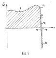
- FIG. 1 shows a characteristic curve K of an asynchronous machine designed as a squirrel-cage rotor.
- the power P or the torque M proportional to it are plotted on the speed n (abscissa) as ordinate values.
- Such removal means a huge drop in performance, especially for smaller electrical networks, such as the ship's electrical system.
- Fig. 1 illustrates how narrow the range .DELTA.n between a switching speed n S at which the machine is connected to the network and the nominal speed n N is if an abrupt load on the network is to be avoided.
- the asynchronous machine operates as a generator and (in field E2 of FIG. 1) delivers power to the network.
- the device described below for controlling a utility turbine coupled to a generator uses the utility turbine directly to start up an asynchronous generator coupled to it.
- 2 to 5 schematically show a utility turbine 1, which is supplied via an exhaust gas supply line 2 for the supercharging of a supercharged internal combustion engine (not shown).
- the utility turbine 1 is coupled to an asynchronous generator 4 via a transmission 3.
- the gases released in the power turbine 1 are passed outside via an exhaust gas discharge line 5.
- At least one shut-off element 6 is arranged in the exhaust gas supply line 2.
- two shut-off elements 6 and 7 are arranged in series, of which at least one can be regulated very finely with respect to its open position and at least one can be closed quickly.
- the shut-off device 6 can be regulated very finely and the shut-off device 7 can be closed quickly. This arrangement enables a very fine regulation of the amount of exhaust gas flowing through to the utility turbine 1 with simultaneous quick closing if this should be necessary in the event of a fault.
- Both shut-off devices 6 and 7 are actuated by compressed air and are closed in the deflated basic position.
- a bypass line 8 branches off from the exhaust gas supply line 2, which bypasses the utility turbine 1 and behind this opens into the exhaust gas discharge line 5.
- a bypass valve 9 is arranged in the bypass line 8, which can be actuated by means of compressed air and is opened in the deflated basic position.
- a preferably adjustable throttle 10 is arranged in the bypass line 8. This has the task of generating a pressure drop when the utility turbine is not in operation, which corresponds approximately to that of the utility turbine. As a result, the internal combustion engine has an approximately constant exhaust gas back pressure, regardless of the operation of the utility turbine.
- a pressure meter 11 which determines the pressure upstream of the turbine p vT, is connected to the exhaust gas supply line 2 immediately before it enters the utility turbine 1.
- the pressure upstream of the turbine p vT is used as a control variable for the shut-off element 6 (or the shut-off elements 6 and 7) on a device for regulating the opening cross section of the shut-off element 6 (or the shut-off elements 6 and 7) and the bypass valve 9 , which controls the opening cross section of the shut-off element 6 in such a way that, in a first phase when the utility turbine 1 starts up, it is initially continuously increased until the pressure p vT has reached a preselected, adjustable pressure p S.
- This process is shown in the diagram of FIG. 6 b by the rising straight line in the left part, in which the valve opening increases from 0 to about 20% in a time interval from 0 to t 1. This is accompanied by an increase in the pressure p vT from 0 to p S , as shown in FIG. 6 b, and an increase in the generator speed from 0 to approximately 50% of the nominal speed n N.
- the shut-off device 6 remains during the time interval from t 1 to t 2, represented by the horizontal course of the valve opening curve in FIG. 6 a.
- the pressure p vT also remains at the level p S during this time.
- the pressure p S is selected so that at the lowest power of the internal combustion engine at which the power turbine 1 is switched on, the asynchronous generator 4 in the case its non-connection to the network would be accelerated to a speed n max which is approximately 5% above its nominal speed n N.
- the degressive curve of the speed curve of the asynchronous generator 4 is shown in the time interval t1 - t2; the speed increase dn / dt reaches a value so low in the range of the nominal speed n N that a safe, shock-free connection of the asynchronous generator 4 to the network is guaranteed at the time t 2.
- shut-off device 6 After connecting to the network in the time interval t2 - t3 the shut-off device 6 is continuously opened up to 100% (Fig. 6 a).
- the pressure p vT also rises to a maximum value (FIG. 6 b).
- the speed of the asynchronous generator 4 now loaded by the load of the network remains largely constant; a slight increase (slip) in the operating speed n B compared to the nominal speed n N is - as explained in connection with FIG. 1 - necessary for energy to be supplied to the network.
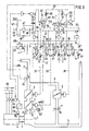
- the pressures p vT and p L and the generator speed n G can be supplied as electrical input signals to a computer which, on the basis of stored setpoints, uses a computer program to generate digital output pulses for actuating electrical servomotors, the latter acting as stepping motors to position the shut-off devices 6 , 7 and the bypass valve 9 regulate and coupled to a circuit breaker control the connection and disconnection of the asynchronous generator 4 to the network.
- the manifold pressure line 16 is divided into three branch lines 18, 19, 20.
- the first branch line 18 has a preferably adjustable throttle 21 and is connected on the input side to a first electromagnetically switchable 3/2-way valve 22.
- a ventilation line 23 in which a preferably adjustable throttle 24 is installed, and a control line 25, which is connected to the shut-off device 6.
- the shut-off element 6 is held in the basic position in the closed position by a spring and acted upon in the opening direction by the pressure in the control line 25.
- the second branch line 19 has a preferably adjustable throttle 26 and is connected on the inlet side to a second electromagnetically switchable 3/2-way valve 27.
- a ventilation line 28 in which a preferably adjustable throttle 29 is installed, and a control line 30, which is connected to the shut-off element 7.
- the shut-off device 7 is held in the basic position in the closed position by a spring and acted upon by the pressure in the control line 30 in the opening direction.
- an additional 2/2-way valve 32 is provided in a branch 31 of the control line 30, which closes the branch 31 in the operating position 32 b and also in the second switching position 32 a when an emergency stop is triggered a vent line 33 leading unthrottled outdoors.
- the third branch line 20 has a preferably adjustable throttle 34 and is connected on the input side to a third electromagnetically switchable 3/2-way valve 35. Further connections are on the 3/2-way valve 35, a ventilation line 36, in which a preferably adjustable throttle 37 is installed and a control line 38, which is connected to the bypass valve 9.
- the bypass valve 9 is held in the open position by a spring in the basic position and is acted upon by the pressure in the control line 38 in the closing direction. Since the bypass valve 9 should open quickly in an emergency, an additional 2/2-way valve 40 is provided in a branch 39 of the control line 38, which closes the branch 39 in the operating position 40 b and this in the second switching position 40 a when a Connects emergency stops with an unthrottled vent line 41 leading to the outside.
- the magnetic switches of the directional control valves 22, 27, 32, 35 and 40 are arranged in parallel in an electrical control circuit 43. They are actuated by a 24 V control voltage which, after closing a main switch 42, actuating a start button 45 activating the control circuit 43 and at the same time a holding circuit 44, and in the directional control valves 22, 27 and 35 additionally after closing an operating switch S22, S27 or S35 one their two terminals.
- the second terminal of the magnetic switch is grounded.
- the third branch line 20 is connected to the control line 38 (switch position 35 b); the directional control valve 40 blocks the branch 39 (switch position 40 b).
- the magnetic switches of the directional control valves 22, 27 and 35 upstream operating switches S22, S27 and S35 are operated by a control device 49.
- a value proportional to the boost pressure p L is supplied to the control device 49 as an input signal. If this is sufficiently high, the switches are closed via a signal line 49 a and the exhaust turbine 1 is subjected to excess exhaust gas. If the value of the boost pressure p L falls below an adjustable minimum value p LÜ , the switches S22, S27 and S35 are opened and the power turbine 1 is thereby deactivated.
- an emergency stop switch 46 is turned on, which is closed in the basic position and ensures that the holding current is maintained at a switching relay 47, which actuates a switch 48 for the holding circuit and a switch 48 a for the control circuit 43.
- the switching relay 47 drops out and thus opens the switches 48 and 48 a.
- switch 48 a is open - regardless of the position of the operating switches S22, S27 and S35 - there is no longer any control voltage at the magnetic switches of the directional control valves 22, 27, 32, 35 and 40, whereby these are spring-loaded in their respective with the addition "a" designated second switching position.
- the directional control valve 27 connects the control line 30 to the ventilation line 28 and simultaneously blocks the second branch line 19; the directional control valve 32 additionally connects the branch 31 to the ventilation line 33.
- the directional control valve 35 connects the control line 38 to the vent line 36 and simultaneously blocks the third branch line 20; the directional control valve 40 additionally connects the branch 39 to the ventilation line 41.
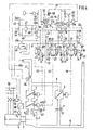
- the pressure p vT is not measured directly by the exhaust gas present in the exhaust gas supply line 2, but indirectly by control air.
- a pressure gauge or, in the present example, the upstream directional control valve 13 switched into the dynamic pressure line 12 are not directly exposed to the hot, aggressive medium exhaust gas.
- the dynamic pressure line 12 can be connected to a control air feed line 51, which is advantageously fed with the control air feed line 14 from a common compressed air source, by means of an electromagnetically actuated 3/2-way valve 50 and with the interposition of an adjustable throttle 60.
- the 3/2-way valve 50 has a vent line 52 as the third controlled connection.
- the directional valve 50 connects the control air feed line 51 to the dynamic pressure line 12, in the second switching position 50 a the dynamic pressure line 12 to the ventilation line 52.
- the directional valve 50 is actuated by a magnetic switch. This is in a branching branch 53 of the electrical control circuit 43.
- An auxiliary switch 54 is connected upstream of the magnetic switch of the directional control valve 50.
- the auxiliary switch 54 is an inverting switch of a mains switch 55, which connects the asynchronous generator 4 to an electrical consumer network 56 on or off. Due to the inversion, the switch 54 is closed when the main switch 55 is open and vice versa.
- the directional control valve 50 assumes the first switch position 50 b, in which the control air feed line 51 and dynamic pressure line 12 are connected to one another.
- Control air the pressure level of which is always above the greatest possible pressure upstream of the turbine p vT , flows via a check valve 57 to the exhaust gas supply line 2 which is switched into the dynamic pressure line 12.
- the check valve 57 is arranged just before the dynamic pressure line 12 opens into the exhaust gas supply line 2 and only there permeable, so that penetration of exhaust gas is prevented.
- the pressure p 1 2 present in the dynamic pressure line 12 between the directional control valve 50 and the check valve 57 which is decisive as a manipulated variable for the upstream directional control valve 13, corresponds to the pressure p vT plus the small pressure drop ⁇ p scaffold at the check valve 57.
- Directional control valve 13 actuated by clean compressed air, the pressure of which, however, is proportional to the pressure p vT of the exhaust gas.
- the already mentioned power switch 55 of the asynchronous generator 4 is actuated by a switching logic 58, which is initially connected to a speed sensor 59.
- the speed sensor 59 determines the current speed n G of the asynchronous generator 4.
- the switching logic 58 stores a speed target value n S , which approximately corresponds to the nominal speed n N of the asynchronous generator 4.
- the actual speed value n G coming from the speed sensor 59 is constantly compared with this target value n S. If the actual speed n G has reached the setpoint n S during startup, the mains switch 55 is closed.
- the control device 49 causes the mains switch 55 to be opened via a signal line 49 b.
- the boost pressure p L has reached the value P LÜ as the input variable of the control device 49, which triggers a closure of the switches S22, S27 and S35. By closing these switches, the magnets of the directional control valves 22, 27, 35 attract and bring them into the switching position "b". As a result, the control line 25 is connected to the branch line 18, the control line 30 to the branch line 19 and the control line 38 to the branch line 20.
- the shut-off devices 6 and 7 are acted upon by control air and open slowly; the bypass valve 9, which is also acted on with control air, closes slowly. As a result, a growing proportion of exhaust gas is routed to the utility turbine 1 via the shut-off devices 6 and 7, while at the same time the exhaust gas flow in the bypass line 8 is reduced.
- the pressure p vT is just so high that it is sufficient to accelerate the power turbine 1 and the asynchronous generator 4, but in the area of the nominal speed n N of the asynchronous generator 4 only causes a small increase in speed that a safe, shock-free Connection to the electrical consumer network 56 is guaranteed.
- the overpressure cutoff shown in FIG. 4 becomes effective. Due to the increased pressure in the dynamic pressure line 12, the ballast directional control valve 13 is pressed into its switching position 13 c. The manifold pressure line 16 is connected to the vent line 15. The resulting pressure reduction in the control lines 25, 30 and 38 causes a slow closing of the shut-off devices 6 and 7 with a simultaneous slow opening of the bypass valve 9. As a result, the pressure upstream of the turbine p vT is reduced to the level p S which is necessary for the proper acceleration and engagement is required.
- the pressure in the dynamic pressure line 12 also drops again and allows the upstream directional control valve 13 to return to the switching position "b".
- a still further pressure drop in the dynamic pressure line 12 would result in a return to the switching position 13 a for a further supply of control air to the control lines 18, 19, 20 and thus for a further opening of the shut-off devices 6 and 7 or a further closing of the bypass - Guide valve 9.
- the pressure p vT is automatically regulated around the level p S.
- the mains switch 55 is triggered and the asynchronous generator 4 is thereby connected to the consumer network 56 (FIG. 5).
- the inverting auxiliary switch 54 coupled to the power switch 55 opens in the branching branch 53 of the control circuit 43, the magnetic switch of the directional control valve 50 dropping and this thereby getting into the switching position 50 a.
- the dynamic pressure line 12 is vented via the vent line 52; the falling pressure in the dynamic pressure line 12 allows the ballast directional control valve to drop back into the switching position 13a.
- the control lines 25, 30 and 38 are acted upon again with control air.
- the shut-off devices 6, 7 slowly open further until the opening is complete, the bypass valve 9 continues to close slowly until it is completely closed.
- the utility turbine 1 is fully loaded by the excess exhaust gas quantity of the internal combustion engine.
- the asynchronous generator 4 is driven to an operating speed n B , which is slightly above its nominal speed n N , and in the process outputs power to the consumer network 56.
- a falling boost pressure p L on the control unit 49 signals that there is no longer enough excess exhaust gas for operation of the power turbine 1.
- the switches S22, S27 and S35 are opened via the signal line 49 a, the directional control valves 22, 27 and 35 are reset to their switching position "a".
- the throttled emptying control lines 25, 30 and 38 cause the shut-off devices 6 and 7 to close slowly or the bypass valve 9 to open slowly.
- the power switch 55 is opened via the signal line 49b and the asynchronous generator 4 is thus separated from the consumer network 56 .
- the opening of the switches S22, S27 and S35 for an operational shutdown can also be done manually.
- the emergency stop switch 46 is opened in the holding circuit 44 which causes the switches 48 and 48 a to hold; thereby opening the switches 48 and 48 a; the control circuit 43 becomes dead.
- the control line 25 of the shut-off element 6 is slowly vented via the throttle 24; the shut-off device 6 closes correspondingly slowly.
- the control lines 30 and 38 are vented unthrottled via the vent lines 33 and 41; the shut-off element 7 closes correspondingly quickly and opens the bypass valve 9.
- the exhaust gas temperature T A is used as a further manipulated variable for controlling the opening cross section of the shut-off elements 6, 7 and the bypass valve 9.
- a temperature meter 64 is arranged in the exhaust gas supply line 2 and is connected on the input side to an actuating device 62.
- the actuating device is articulated on the output side to a lever 61 which can be pivoted about a fixed pivot point 63.
- the spring 17 is supported with its base 17 a.
- the support point 17 a is brought into a position further away from the upstream directional valve 13. It is thereby achieved that the ballast valve gets into the switching position "b" at a higher exhaust gas temperature even at a lower pressure p vT . A too rapid acceleration of the utility turbine is avoided by the resulting smaller opening of the shut-off elements 6, 7.
- the device according to the invention thus ensures reliable control of the entire utility turbine generator system in all operating areas.
- the operator is considerably relieved by the largely automatic connection and disconnection of the system.
Landscapes
- Engineering & Computer Science (AREA)
- Mechanical Engineering (AREA)
- General Engineering & Computer Science (AREA)
- Chemical & Material Sciences (AREA)
- Combustion & Propulsion (AREA)
- Physics & Mathematics (AREA)
- Fluid Mechanics (AREA)
- Control Of Turbines (AREA)
- Supercharger (AREA)
Applications Claiming Priority (2)
| Application Number | Priority Date | Filing Date | Title |
|---|---|---|---|
| DE3916242 | 1989-05-18 | ||
| DE3916242A DE3916242C1 (enExample) | 1989-05-18 | 1989-05-18 |
Publications (3)
| Publication Number | Publication Date |
|---|---|
| EP0398138A2 EP0398138A2 (de) | 1990-11-22 |
| EP0398138A3 EP0398138A3 (de) | 1991-06-05 |
| EP0398138B1 true EP0398138B1 (de) | 1993-04-21 |
Family
ID=6380922
Family Applications (1)
| Application Number | Title | Priority Date | Filing Date |
|---|---|---|---|
| EP90108695A Expired - Lifetime EP0398138B1 (de) | 1989-05-18 | 1990-05-09 | Vorrichtung zur Steuerung einer mit einem Generator gekoppelten Nutzturbine |
Country Status (3)
| Country | Link |
|---|---|
| EP (1) | EP0398138B1 (enExample) |
| JP (1) | JP2977580B2 (enExample) |
| DE (2) | DE3916242C1 (enExample) |
Families Citing this family (3)
| Publication number | Priority date | Publication date | Assignee | Title |
|---|---|---|---|---|
| CZ382892A3 (en) * | 1992-02-20 | 1993-09-15 | Asea Brown Boveri | Device with a gas turbine and method for starting thereof |
| DE4221734C2 (de) * | 1992-07-02 | 1996-01-04 | Man B & W Diesel Ag | Aufladesystem für Brennkraftmaschinen |
| KR200452870Y1 (ko) * | 2009-04-02 | 2011-03-29 | 한국서부발전 주식회사 | 토그 컨버터 가이드 벤용 위치 신호 처리 장치 |
Family Cites Families (2)
| Publication number | Priority date | Publication date | Assignee | Title |
|---|---|---|---|---|
| DE3705310A1 (de) * | 1987-02-19 | 1988-09-01 | Licentia Gmbh | Abgasturbinen-generatoranlage |
| DE3729117C1 (en) * | 1987-09-01 | 1988-11-03 | Man B & W Diesel Gmbh | Internal combustion engine system |
-
1989
- 1989-05-18 DE DE3916242A patent/DE3916242C1/de not_active Expired - Fee Related
-
1990
- 1990-05-09 EP EP90108695A patent/EP0398138B1/de not_active Expired - Lifetime
- 1990-05-09 DE DE9090108695T patent/DE59001230D1/de not_active Expired - Lifetime
- 1990-05-11 JP JP2122786A patent/JP2977580B2/ja not_active Expired - Lifetime
Also Published As
| Publication number | Publication date |
|---|---|
| DE3916242C1 (enExample) | 1990-06-13 |
| EP0398138A2 (de) | 1990-11-22 |
| JPH039031A (ja) | 1991-01-16 |
| DE59001230D1 (de) | 1993-05-27 |
| JP2977580B2 (ja) | 1999-11-15 |
| EP0398138A3 (de) | 1991-06-05 |
Similar Documents
| Publication | Publication Date | Title |
|---|---|---|
| DE3023550C2 (enExample) | ||
| DE4001511A1 (de) | Luftzufuhr-steuersystem fuer eine brennkraftmaschine | |
| DE1613733A1 (de) | Notaggregat zu kurzzeitigen Lieferung elektrischen Stromes | |
| DE2147394C2 (de) | Steuerung zur Regelung von Kreiselverdichtern für ein Kühlsystem | |
| DE3101476A1 (de) | "vorrichtung und verfahren zur automatischen geschwindigkeitseinstellung bei kraftfahrzeugen" | |
| DE3730779A1 (de) | Magnetgesteuerte ventileinrichtung | |
| EP1880939A1 (de) | Flugzeugklimaanlage und Verfahren zum Betreiben einer Flugzeugklimaanlage | |
| DE3517646C2 (enExample) | ||
| EP0556593B1 (de) | Gasturbinenanlage | |
| DE10164789B4 (de) | Verfahren und Vorrichtung zur Voraktivierung mindestens eines elektrischen Aufladegeräts in einem Kraftfahrzeug | |
| EP0398138B1 (de) | Vorrichtung zur Steuerung einer mit einem Generator gekoppelten Nutzturbine | |
| EP1020388B1 (de) | Luftsteuer- und/oder Luftregelungseinrichtung | |
| DE3531137C2 (enExample) | ||
| DE2142787C3 (de) | Brennstoffregelanlage für Gasturbinen | |
| DE102017124586A1 (de) | Ladermotorsystem für ein Kraftfahrzeug | |
| DE3212498C2 (de) | Steuerung für die Zu- und Abschaltung von Abgasturboladern | |
| DE4221734C2 (de) | Aufladesystem für Brennkraftmaschinen | |
| DE2448851C3 (de) | Einrichtung zum Einstellen der Bremskraft einer Bremse an einer Förderanlage mit geneigter Förderrichtung | |
| DE3004199C2 (de) | Vorrichtung zum Absperren der Brennstoffzufuhr im Schiebebetrieb eines Verbrennungsmotors | |
| DE4408798B4 (de) | Steuersystem einer Vorrichtung zur Kühlung eines Verbrennungsmotors | |
| DE10011601C2 (de) | Antriebseinrichtung für Schiffspropeller | |
| DE2414293C3 (de) | Last-Kompensationseinrichtung für aufgeladene Brennkraftmaschinen | |
| DE19951592A1 (de) | Regelung der Bremsleistung einer Brennkraftmaschine | |
| EP0151805B1 (de) | Einrichtung zur elektrischen Leerlaufregelung von Verbrennungsmotoren | |
| DE19842751A1 (de) | Ansauganordnung für eine Brennkraftmaschine |
Legal Events
| Date | Code | Title | Description |
|---|---|---|---|
| PUAI | Public reference made under article 153(3) epc to a published international application that has entered the european phase |
Free format text: ORIGINAL CODE: 0009012 |
|
| AK | Designated contracting states |
Kind code of ref document: A2 Designated state(s): CH DE GB IT LI |
|
| PUAL | Search report despatched |
Free format text: ORIGINAL CODE: 0009013 |
|
| AK | Designated contracting states |
Kind code of ref document: A3 Designated state(s): CH DE GB IT LI |
|
| 17P | Request for examination filed |
Effective date: 19910504 |
|
| 17Q | First examination report despatched |
Effective date: 19920706 |
|
| ITF | It: translation for a ep patent filed | ||
| GRAA | (expected) grant |
Free format text: ORIGINAL CODE: 0009210 |
|
| AK | Designated contracting states |
Kind code of ref document: B1 Designated state(s): CH DE GB IT LI |
|
| REF | Corresponds to: |
Ref document number: 59001230 Country of ref document: DE Date of ref document: 19930527 |
|
| GBT | Gb: translation of ep patent filed (gb section 77(6)(a)/1977) |
Effective date: 19930727 |
|
| PLBE | No opposition filed within time limit |
Free format text: ORIGINAL CODE: 0009261 |
|
| STAA | Information on the status of an ep patent application or granted ep patent |
Free format text: STATUS: NO OPPOSITION FILED WITHIN TIME LIMIT |
|
| 26N | No opposition filed | ||
| REG | Reference to a national code |
Ref country code: GB Ref legal event code: IF02 |
|
| PGFP | Annual fee paid to national office [announced via postgrant information from national office to epo] |
Ref country code: IT Payment date: 20060531 Year of fee payment: 17 |
|
| REG | Reference to a national code |
Ref country code: CH Ref legal event code: PFA Owner name: MAN B & W DIESEL AKTIENGESELLSCHAFT Free format text: MAN B & W DIESEL AKTIENGESELLSCHAFT#STADTBACHSTRASSE 1 POSTFACH 10 00 80#D-86153 AUGSBURG (DE) -TRANSFER TO- MAN B & W DIESEL AKTIENGESELLSCHAFT#STADTBACHSTRASSE 1 POSTFACH 10 00 80#D-86153 AUGSBURG (DE) |
|
| PGFP | Annual fee paid to national office [announced via postgrant information from national office to epo] |
Ref country code: DE Payment date: 20090525 Year of fee payment: 20 |
|
| PG25 | Lapsed in a contracting state [announced via postgrant information from national office to epo] |
Ref country code: IT Free format text: LAPSE BECAUSE OF NON-PAYMENT OF DUE FEES Effective date: 20070509 |
|
| PGFP | Annual fee paid to national office [announced via postgrant information from national office to epo] |
Ref country code: CH Payment date: 20090518 Year of fee payment: 20 |
|
| PGFP | Annual fee paid to national office [announced via postgrant information from national office to epo] |
Ref country code: GB Payment date: 20090522 Year of fee payment: 20 |
|
| REG | Reference to a national code |
Ref country code: CH Ref legal event code: PL |
|
| REG | Reference to a national code |
Ref country code: GB Ref legal event code: PE20 Expiry date: 20100508 |
|
| PG25 | Lapsed in a contracting state [announced via postgrant information from national office to epo] |
Ref country code: GB Free format text: LAPSE BECAUSE OF EXPIRATION OF PROTECTION Effective date: 20100508 |
|
| PG25 | Lapsed in a contracting state [announced via postgrant information from national office to epo] |
Ref country code: DE Free format text: LAPSE BECAUSE OF EXPIRATION OF PROTECTION Effective date: 20100509 |