EP0398138B1 - Vorrichtung zur Steuerung einer mit einem Generator gekoppelten Nutzturbine - Google Patents
Vorrichtung zur Steuerung einer mit einem Generator gekoppelten Nutzturbine Download PDFInfo
- Publication number
- EP0398138B1 EP0398138B1 EP90108695A EP90108695A EP0398138B1 EP 0398138 B1 EP0398138 B1 EP 0398138B1 EP 90108695 A EP90108695 A EP 90108695A EP 90108695 A EP90108695 A EP 90108695A EP 0398138 B1 EP0398138 B1 EP 0398138B1
- Authority
- EP
- European Patent Office
- Prior art keywords
- line
- shut
- pressure
- turbine
- valve
- Prior art date
- Legal status (The legal status is an assumption and is not a legal conclusion. Google has not performed a legal analysis and makes no representation as to the accuracy of the status listed.)
- Expired - Lifetime
Links
- 238000002485 combustion reaction Methods 0.000 claims description 8
- 230000001133 acceleration Effects 0.000 claims description 7
- 239000002912 waste gas Substances 0.000 claims 10
- 230000001419 dependent effect Effects 0.000 claims 1
- 239000007789 gas Substances 0.000 description 30
- 238000011144 upstream manufacturing Methods 0.000 description 16
- 238000009423 ventilation Methods 0.000 description 9
- 230000001276 controlling effect Effects 0.000 description 5
- 230000001105 regulatory effect Effects 0.000 description 5
- 238000010586 diagram Methods 0.000 description 3
- 238000000034 method Methods 0.000 description 3
- 230000001360 synchronised effect Effects 0.000 description 3
- 230000001960 triggered effect Effects 0.000 description 3
- 241001136792 Alle Species 0.000 description 1
- 230000003213 activating effect Effects 0.000 description 1
- 230000005540 biological transmission Effects 0.000 description 1
- 238000004590 computer program Methods 0.000 description 1
- 230000008878 coupling Effects 0.000 description 1
- 238000010168 coupling process Methods 0.000 description 1
- 238000005859 coupling reaction Methods 0.000 description 1
- 230000003247 decreasing effect Effects 0.000 description 1
- 230000002996 emotional effect Effects 0.000 description 1
- 230000007257 malfunction Effects 0.000 description 1
- 230000035515 penetration Effects 0.000 description 1
- 230000000630 rising effect Effects 0.000 description 1
- 239000007858 starting material Substances 0.000 description 1
Images



Classifications
-
- F—MECHANICAL ENGINEERING; LIGHTING; HEATING; WEAPONS; BLASTING
- F02—COMBUSTION ENGINES; HOT-GAS OR COMBUSTION-PRODUCT ENGINE PLANTS
- F02C—GAS-TURBINE PLANTS; AIR INTAKES FOR JET-PROPULSION PLANTS; CONTROLLING FUEL SUPPLY IN AIR-BREATHING JET-PROPULSION PLANTS
- F02C9/00—Controlling gas-turbine plants; Controlling fuel supply in air- breathing jet-propulsion plants
- F02C9/16—Control of working fluid flow
-
- F—MECHANICAL ENGINEERING; LIGHTING; HEATING; WEAPONS; BLASTING
- F01—MACHINES OR ENGINES IN GENERAL; ENGINE PLANTS IN GENERAL; STEAM ENGINES
- F01D—NON-POSITIVE DISPLACEMENT MACHINES OR ENGINES, e.g. STEAM TURBINES
- F01D17/00—Regulating or controlling by varying flow
- F01D17/20—Devices dealing with sensing elements or final actuators or transmitting means between them, e.g. power-assisted
- F01D17/22—Devices dealing with sensing elements or final actuators or transmitting means between them, e.g. power-assisted the operation or power assistance being predominantly non-mechanical
- F01D17/26—Devices dealing with sensing elements or final actuators or transmitting means between them, e.g. power-assisted the operation or power assistance being predominantly non-mechanical fluid, e.g. hydraulic
Definitions
- the invention relates to a device for controlling a utility turbine coupled to a generator, which utilizes exhaust gas of a supercharged internal combustion engine that is not required for charging, according to the preamble of patent claim 1.
- a generic device is known from DE-A-37 05 310.
- a commercial turbine drives a synchronous generator there, which feeds the electrical power generated into a network.
- the generator is driven by the turbine only after the synchronous speed of the generator has been reached;
- a special asynchronous starter motor is required to ramp up to the synchronous speed.
- the object of the invention is to switch a device for controlling a utility turbine, in which the generator is started up directly by the turbine coupled to it.
- the device according to the invention has the following advantages: Depending on the pressure in front of the turbine as a control variable, the generator is started up on an acceleration curve with a degressive characteristic. In the area of the nominal speed of the generator, the speed increase is so small that its safe connection is guaranteed. A sudden load on the network is effectively avoided. Pressure fluctuations in the exhaust gas supply line are automatically compensated.
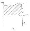
- FIG. 1 shows a characteristic curve K of an asynchronous machine designed as a squirrel-cage rotor.
- the power P or the torque M proportional to it are plotted on the speed n (abscissa) as ordinate values.
- Such removal means a huge drop in performance, especially for smaller electrical networks, such as the ship's electrical system.
- Fig. 1 illustrates how narrow the range .DELTA.n between a switching speed n S at which the machine is connected to the network and the nominal speed n N is if an abrupt load on the network is to be avoided.
- the asynchronous machine operates as a generator and (in field E2 of FIG. 1) delivers power to the network.
- the device described below for controlling a utility turbine coupled to a generator uses the utility turbine directly to start up an asynchronous generator coupled to it.
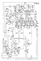
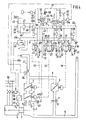
- 2 to 5 schematically show a utility turbine 1, which is supplied via an exhaust gas supply line 2 for the supercharging of a supercharged internal combustion engine (not shown).
- the utility turbine 1 is coupled to an asynchronous generator 4 via a transmission 3.
- the gases released in the power turbine 1 are passed outside via an exhaust gas discharge line 5.
- At least one shut-off element 6 is arranged in the exhaust gas supply line 2.
- two shut-off elements 6 and 7 are arranged in series, of which at least one can be regulated very finely with respect to its open position and at least one can be closed quickly.
- the shut-off device 6 can be regulated very finely and the shut-off device 7 can be closed quickly. This arrangement enables a very fine regulation of the amount of exhaust gas flowing through to the utility turbine 1 with simultaneous quick closing if this should be necessary in the event of a fault.
- Both shut-off devices 6 and 7 are actuated by compressed air and are closed in the deflated basic position.
- a bypass line 8 branches off from the exhaust gas supply line 2, which bypasses the utility turbine 1 and behind this opens into the exhaust gas discharge line 5.
- a bypass valve 9 is arranged in the bypass line 8, which can be actuated by means of compressed air and is opened in the deflated basic position.
- a preferably adjustable throttle 10 is arranged in the bypass line 8. This has the task of generating a pressure drop when the utility turbine is not in operation, which corresponds approximately to that of the utility turbine. As a result, the internal combustion engine has an approximately constant exhaust gas back pressure, regardless of the operation of the utility turbine.
- a pressure meter 11 which determines the pressure upstream of the turbine p vT, is connected to the exhaust gas supply line 2 immediately before it enters the utility turbine 1.
- the pressure upstream of the turbine p vT is used as a control variable for the shut-off element 6 (or the shut-off elements 6 and 7) on a device for regulating the opening cross section of the shut-off element 6 (or the shut-off elements 6 and 7) and the bypass valve 9 , which controls the opening cross section of the shut-off element 6 in such a way that, in a first phase when the utility turbine 1 starts up, it is initially continuously increased until the pressure p vT has reached a preselected, adjustable pressure p S.
- This process is shown in the diagram of FIG. 6 b by the rising straight line in the left part, in which the valve opening increases from 0 to about 20% in a time interval from 0 to t 1. This is accompanied by an increase in the pressure p vT from 0 to p S , as shown in FIG. 6 b, and an increase in the generator speed from 0 to approximately 50% of the nominal speed n N.
- the shut-off device 6 remains during the time interval from t 1 to t 2, represented by the horizontal course of the valve opening curve in FIG. 6 a.
- the pressure p vT also remains at the level p S during this time.
- the pressure p S is selected so that at the lowest power of the internal combustion engine at which the power turbine 1 is switched on, the asynchronous generator 4 in the case its non-connection to the network would be accelerated to a speed n max which is approximately 5% above its nominal speed n N.
- the degressive curve of the speed curve of the asynchronous generator 4 is shown in the time interval t1 - t2; the speed increase dn / dt reaches a value so low in the range of the nominal speed n N that a safe, shock-free connection of the asynchronous generator 4 to the network is guaranteed at the time t 2.
- shut-off device 6 After connecting to the network in the time interval t2 - t3 the shut-off device 6 is continuously opened up to 100% (Fig. 6 a).
- the pressure p vT also rises to a maximum value (FIG. 6 b).
- the speed of the asynchronous generator 4 now loaded by the load of the network remains largely constant; a slight increase (slip) in the operating speed n B compared to the nominal speed n N is - as explained in connection with FIG. 1 - necessary for energy to be supplied to the network.
- the pressures p vT and p L and the generator speed n G can be supplied as electrical input signals to a computer which, on the basis of stored setpoints, uses a computer program to generate digital output pulses for actuating electrical servomotors, the latter acting as stepping motors to position the shut-off devices 6 , 7 and the bypass valve 9 regulate and coupled to a circuit breaker control the connection and disconnection of the asynchronous generator 4 to the network.
- the manifold pressure line 16 is divided into three branch lines 18, 19, 20.
- the first branch line 18 has a preferably adjustable throttle 21 and is connected on the input side to a first electromagnetically switchable 3/2-way valve 22.
- a ventilation line 23 in which a preferably adjustable throttle 24 is installed, and a control line 25, which is connected to the shut-off device 6.
- the shut-off element 6 is held in the basic position in the closed position by a spring and acted upon in the opening direction by the pressure in the control line 25.
- the second branch line 19 has a preferably adjustable throttle 26 and is connected on the inlet side to a second electromagnetically switchable 3/2-way valve 27.
- a ventilation line 28 in which a preferably adjustable throttle 29 is installed, and a control line 30, which is connected to the shut-off element 7.
- the shut-off device 7 is held in the basic position in the closed position by a spring and acted upon by the pressure in the control line 30 in the opening direction.
- an additional 2/2-way valve 32 is provided in a branch 31 of the control line 30, which closes the branch 31 in the operating position 32 b and also in the second switching position 32 a when an emergency stop is triggered a vent line 33 leading unthrottled outdoors.
- the third branch line 20 has a preferably adjustable throttle 34 and is connected on the input side to a third electromagnetically switchable 3/2-way valve 35. Further connections are on the 3/2-way valve 35, a ventilation line 36, in which a preferably adjustable throttle 37 is installed and a control line 38, which is connected to the bypass valve 9.
- the bypass valve 9 is held in the open position by a spring in the basic position and is acted upon by the pressure in the control line 38 in the closing direction. Since the bypass valve 9 should open quickly in an emergency, an additional 2/2-way valve 40 is provided in a branch 39 of the control line 38, which closes the branch 39 in the operating position 40 b and this in the second switching position 40 a when a Connects emergency stops with an unthrottled vent line 41 leading to the outside.
- the magnetic switches of the directional control valves 22, 27, 32, 35 and 40 are arranged in parallel in an electrical control circuit 43. They are actuated by a 24 V control voltage which, after closing a main switch 42, actuating a start button 45 activating the control circuit 43 and at the same time a holding circuit 44, and in the directional control valves 22, 27 and 35 additionally after closing an operating switch S22, S27 or S35 one their two terminals.
- the second terminal of the magnetic switch is grounded.
- the third branch line 20 is connected to the control line 38 (switch position 35 b); the directional control valve 40 blocks the branch 39 (switch position 40 b).
- the magnetic switches of the directional control valves 22, 27 and 35 upstream operating switches S22, S27 and S35 are operated by a control device 49.
- a value proportional to the boost pressure p L is supplied to the control device 49 as an input signal. If this is sufficiently high, the switches are closed via a signal line 49 a and the exhaust turbine 1 is subjected to excess exhaust gas. If the value of the boost pressure p L falls below an adjustable minimum value p LÜ , the switches S22, S27 and S35 are opened and the power turbine 1 is thereby deactivated.
- an emergency stop switch 46 is turned on, which is closed in the basic position and ensures that the holding current is maintained at a switching relay 47, which actuates a switch 48 for the holding circuit and a switch 48 a for the control circuit 43.
- the switching relay 47 drops out and thus opens the switches 48 and 48 a.
- switch 48 a is open - regardless of the position of the operating switches S22, S27 and S35 - there is no longer any control voltage at the magnetic switches of the directional control valves 22, 27, 32, 35 and 40, whereby these are spring-loaded in their respective with the addition "a" designated second switching position.
- the directional control valve 27 connects the control line 30 to the ventilation line 28 and simultaneously blocks the second branch line 19; the directional control valve 32 additionally connects the branch 31 to the ventilation line 33.
- the directional control valve 35 connects the control line 38 to the vent line 36 and simultaneously blocks the third branch line 20; the directional control valve 40 additionally connects the branch 39 to the ventilation line 41.
- the pressure p vT is not measured directly by the exhaust gas present in the exhaust gas supply line 2, but indirectly by control air.
- a pressure gauge or, in the present example, the upstream directional control valve 13 switched into the dynamic pressure line 12 are not directly exposed to the hot, aggressive medium exhaust gas.
- the dynamic pressure line 12 can be connected to a control air feed line 51, which is advantageously fed with the control air feed line 14 from a common compressed air source, by means of an electromagnetically actuated 3/2-way valve 50 and with the interposition of an adjustable throttle 60.
- the 3/2-way valve 50 has a vent line 52 as the third controlled connection.
- the directional valve 50 connects the control air feed line 51 to the dynamic pressure line 12, in the second switching position 50 a the dynamic pressure line 12 to the ventilation line 52.
- the directional valve 50 is actuated by a magnetic switch. This is in a branching branch 53 of the electrical control circuit 43.
- An auxiliary switch 54 is connected upstream of the magnetic switch of the directional control valve 50.
- the auxiliary switch 54 is an inverting switch of a mains switch 55, which connects the asynchronous generator 4 to an electrical consumer network 56 on or off. Due to the inversion, the switch 54 is closed when the main switch 55 is open and vice versa.
- the directional control valve 50 assumes the first switch position 50 b, in which the control air feed line 51 and dynamic pressure line 12 are connected to one another.
- Control air the pressure level of which is always above the greatest possible pressure upstream of the turbine p vT , flows via a check valve 57 to the exhaust gas supply line 2 which is switched into the dynamic pressure line 12.
- the check valve 57 is arranged just before the dynamic pressure line 12 opens into the exhaust gas supply line 2 and only there permeable, so that penetration of exhaust gas is prevented.
- the pressure p 1 2 present in the dynamic pressure line 12 between the directional control valve 50 and the check valve 57 which is decisive as a manipulated variable for the upstream directional control valve 13, corresponds to the pressure p vT plus the small pressure drop ⁇ p scaffold at the check valve 57.
- Directional control valve 13 actuated by clean compressed air, the pressure of which, however, is proportional to the pressure p vT of the exhaust gas.
- the already mentioned power switch 55 of the asynchronous generator 4 is actuated by a switching logic 58, which is initially connected to a speed sensor 59.
- the speed sensor 59 determines the current speed n G of the asynchronous generator 4.
- the switching logic 58 stores a speed target value n S , which approximately corresponds to the nominal speed n N of the asynchronous generator 4.
- the actual speed value n G coming from the speed sensor 59 is constantly compared with this target value n S. If the actual speed n G has reached the setpoint n S during startup, the mains switch 55 is closed.
- the control device 49 causes the mains switch 55 to be opened via a signal line 49 b.
- the boost pressure p L has reached the value P LÜ as the input variable of the control device 49, which triggers a closure of the switches S22, S27 and S35. By closing these switches, the magnets of the directional control valves 22, 27, 35 attract and bring them into the switching position "b". As a result, the control line 25 is connected to the branch line 18, the control line 30 to the branch line 19 and the control line 38 to the branch line 20.
- the shut-off devices 6 and 7 are acted upon by control air and open slowly; the bypass valve 9, which is also acted on with control air, closes slowly. As a result, a growing proportion of exhaust gas is routed to the utility turbine 1 via the shut-off devices 6 and 7, while at the same time the exhaust gas flow in the bypass line 8 is reduced.
- the pressure p vT is just so high that it is sufficient to accelerate the power turbine 1 and the asynchronous generator 4, but in the area of the nominal speed n N of the asynchronous generator 4 only causes a small increase in speed that a safe, shock-free Connection to the electrical consumer network 56 is guaranteed.
- the overpressure cutoff shown in FIG. 4 becomes effective. Due to the increased pressure in the dynamic pressure line 12, the ballast directional control valve 13 is pressed into its switching position 13 c. The manifold pressure line 16 is connected to the vent line 15. The resulting pressure reduction in the control lines 25, 30 and 38 causes a slow closing of the shut-off devices 6 and 7 with a simultaneous slow opening of the bypass valve 9. As a result, the pressure upstream of the turbine p vT is reduced to the level p S which is necessary for the proper acceleration and engagement is required.
- the pressure in the dynamic pressure line 12 also drops again and allows the upstream directional control valve 13 to return to the switching position "b".
- a still further pressure drop in the dynamic pressure line 12 would result in a return to the switching position 13 a for a further supply of control air to the control lines 18, 19, 20 and thus for a further opening of the shut-off devices 6 and 7 or a further closing of the bypass - Guide valve 9.
- the pressure p vT is automatically regulated around the level p S.
- the mains switch 55 is triggered and the asynchronous generator 4 is thereby connected to the consumer network 56 (FIG. 5).
- the inverting auxiliary switch 54 coupled to the power switch 55 opens in the branching branch 53 of the control circuit 43, the magnetic switch of the directional control valve 50 dropping and this thereby getting into the switching position 50 a.
- the dynamic pressure line 12 is vented via the vent line 52; the falling pressure in the dynamic pressure line 12 allows the ballast directional control valve to drop back into the switching position 13a.
- the control lines 25, 30 and 38 are acted upon again with control air.
- the shut-off devices 6, 7 slowly open further until the opening is complete, the bypass valve 9 continues to close slowly until it is completely closed.
- the utility turbine 1 is fully loaded by the excess exhaust gas quantity of the internal combustion engine.
- the asynchronous generator 4 is driven to an operating speed n B , which is slightly above its nominal speed n N , and in the process outputs power to the consumer network 56.
- a falling boost pressure p L on the control unit 49 signals that there is no longer enough excess exhaust gas for operation of the power turbine 1.
- the switches S22, S27 and S35 are opened via the signal line 49 a, the directional control valves 22, 27 and 35 are reset to their switching position "a".
- the throttled emptying control lines 25, 30 and 38 cause the shut-off devices 6 and 7 to close slowly or the bypass valve 9 to open slowly.
- the power switch 55 is opened via the signal line 49b and the asynchronous generator 4 is thus separated from the consumer network 56 .
- the opening of the switches S22, S27 and S35 for an operational shutdown can also be done manually.
- the emergency stop switch 46 is opened in the holding circuit 44 which causes the switches 48 and 48 a to hold; thereby opening the switches 48 and 48 a; the control circuit 43 becomes dead.
- the control line 25 of the shut-off element 6 is slowly vented via the throttle 24; the shut-off device 6 closes correspondingly slowly.
- the control lines 30 and 38 are vented unthrottled via the vent lines 33 and 41; the shut-off element 7 closes correspondingly quickly and opens the bypass valve 9.
- the exhaust gas temperature T A is used as a further manipulated variable for controlling the opening cross section of the shut-off elements 6, 7 and the bypass valve 9.
- a temperature meter 64 is arranged in the exhaust gas supply line 2 and is connected on the input side to an actuating device 62.
- the actuating device is articulated on the output side to a lever 61 which can be pivoted about a fixed pivot point 63.
- the spring 17 is supported with its base 17 a.
- the support point 17 a is brought into a position further away from the upstream directional valve 13. It is thereby achieved that the ballast valve gets into the switching position "b" at a higher exhaust gas temperature even at a lower pressure p vT . A too rapid acceleration of the utility turbine is avoided by the resulting smaller opening of the shut-off elements 6, 7.
- the device according to the invention thus ensures reliable control of the entire utility turbine generator system in all operating areas.
- the operator is considerably relieved by the largely automatic connection and disconnection of the system.
Landscapes
- Engineering & Computer Science (AREA)
- Mechanical Engineering (AREA)
- General Engineering & Computer Science (AREA)
- Chemical & Material Sciences (AREA)
- Combustion & Propulsion (AREA)
- Physics & Mathematics (AREA)
- Fluid Mechanics (AREA)
- Control Of Turbines (AREA)
- Supercharger (AREA)
Description
- Die Erfindung betrifft eine Vorrichtung zur Steuerung einer mit einem Generator gekoppelten Nutzturbine, die für die Aufladung nicht benötigtes Abgas einer aufgeladenen Brennkraftmaschine verwertet, gemäß dem Oberbegriff des Patentanspruchs 1.
- Aus der DE-A-37 05 310 ist eine gattungsgemäße Vorrichtung bekannt. Eine Nutzturbine treibt dort einen Synchrongenerator, der die erzeugte elektrische Leistung in ein Netz einspeist. Der Antrieb des Generators durch die Turbine erfolgt erst nach Erreichen der Synchrondrehzahl des Generators; zum Hochfahren auf die Synchrondrehzahl ist dort ein spezieller Asynchron-Anwurfmotor erforderlich.
- Der Erfindung liegt die Aufgabe zugrunde, eine Vorrichtung zur Steuerung einer Nutzturbine zu schalten, bei der der Generator unmittelbar von der mit ihm gekoppelten Turbine hochgefahren wird.
- Diese Aufgabe wird durch die Merkmale im kennzeichnenden Teil des Patentanspruchs 1 gelöst. Die erfindungsgemäße Vorrichtung bringt folgende Vorteile:
In Abhängigkeit von dem vor der Turbine anstehenden Druck als Steuergröße erfolgt das Hochfahren des Generators auf einer Beschleunigungskurve mit degressiver Kennlinie. Im Bereich der Nenndrehzahl des Generators ist dabei der Drehzahlanstieg derart gering, daß dessen sicheres Zuschalten gewährleistet ist. Eine stoßartige Belastung des Netzes wird wirksam vermieden. Druckschwankungen in der Abgaszufuhrleitung werden selbsttätig ausgeregelt. - Vorteilhafte Ausgestaltungen der Erfindung sind den Unteransprüchen zu entnehmen.
- Es zeigt
- Fig. 1
- ein Leistungs/Drehzahl-Diagramm einer Asynchronmaschine,
- Fig. 2
- eine erfindungsgemäße Vorrichtung in der Startphase,
- Fig. 3
- eine erfindungsgemäße Vorrichtung in der Beschleunigungsphase,
- Fig. 4
- eine erfindungsgemäße Vorrichtung bei der Überdruckregelung in der Beschleunigungsphase,
- Fig. 5
- eine erfindungsgemäße Vorrichtung in der Betriebsphase,
- Fig. 6 a-c
- ein Diagramm für Turbinendrehzahl, Druck vor Turbine und Öffnung des zweiten Absperrorgans während verschiedener Betriebsphasen.
- In Fig. 1 ist eine Kennlinie K einer als Käfigläufer ausgebildeten Asynchronmaschine dargestellt. Anhand dieser Kennlinie K soll zunächst kurz die Problematik des Anfahrens und Zuschaltens einer solchen Maschine an ein Netz betrachtet werden. Über der Drehzahl n (Abszisse) sind als Ordinatenwerte die Leistung P bzw. das dazu proportionale Moment M aufgetragen. Ein Hochfahren der Maschine als Motor von einer Drehzahl n = 0 auf eine Nenndrehzahl nN, die sich aus Netzfrequenz und Polpaarzahl ergibt, würde entsprechend der dafür benötigten Zeitdauer dem Netz eine Energiemenge E₁ entnehmen, die zur rechtssteigend schraffierten Fläche E₁ proportional ist. Eine solche Entnahme bedeutet insbesondere für kleinere elektrische Netze, wie das Bordnetz eines Schiffes, einen gewaltigen Leistungseinbruch.
- Ein Hochfahren der Maschine ohne deren Kopplung ans Netz mittels einer Arbeitsmaschine und das anschließende Zuschalten ans Netz stellen aufgrund der Steilheit der Kennlinie K im Bereich der Nenndrehzahl nN hohe Anforderungen an eine Vorrichtung zur Steuerung dieses Vorgangs. Fig. 1 verdeutlicht, wie schmal der Bereich Δ n zwischen einer Schaltdrehzahl nS, bei der die Maschine ans Netz geschaltet wird, und der Nenndrehzahl nN ist, wenn eine stoßhafte Belastung des Netzes vermieden werden soll.
- Bei einer Überschreitung der Nenndrehzahl nN in Richtung zur Betriebsdrehzahl nB arbeitet die Asynchronmaschine als Generator und gibt (im Feld E2 der Fig. 1) Leistung ans Netz ab.
- Die nachfolgend beschriebene Vorrichtung zur Steuerung einer mit einem Generator gekoppelten Nutzturbine verwendet die Nutzturbine unmittelbar zum Hochfahren eines mit ihr gekoppelten Asynchrongenerators. In den Fig. 2 bis 5 ist schematisch eine Nutzturbine 1 dargestellt, der über eine Abgaszufuhrleitung 2 für die Aufladung einer nicht dargestellten aufgeladenen Brennkraftmaschine nicht benötigtes Abgas zugeführt wird. Die Nutzturbine 1 ist über ein Getriebe 3 mit einem Asynchrongenerator 4 gekoppelt. Die in der Nutzturbine 1 entspannten Gase werden über eine Abgasabfuhrleitung 5 ins Freie geleitet.
- In der Abgaszufuhrleitung 2 ist wenigstens ein Absperrorgan 6 angeordnet. In einer bevorzugten Ausführungsform sind jedoch - wie dargestellt - zwei Absperrorgane 6 und 7 in Reihe hintereinander angeordnet, von denen wenigstens eines bezüglich seiner Öffnungsstellung sehr fein regelbar und wenigstens eines schnell schließbar ist. So ist im Ausführungsbeispiel das Absperrorgan 6 sehr fein regelbar und das Absperrorgan 7 ist schnell schließbar. Diese Anordnung ermöglicht eine sehr feine Regulierung der zur Nutzturbine 1 durchfließenden Abgasmenge bei gleichzeitiger schneller Schließbarkeit, wenn diese in einem Störungsfall erforderlich werden sollte. Beide Absperrorgane 6 und 7 werden mittels Druckluft betätigt und sind in entlüfteter Grundstellung geschlossen.
- Vor den Absperrorganen 6, 7 zweigt von der Abgaszufuhrleitung 2 eine Bypass-Leitung 8 ab, die die Nutzturbine 1 umgeht und hinter dieser in die Abgasabfuhrleitung 5 einmündet. In der Bypass-Leitung 8 ist ein Bypass-Ventil 9 angeordnet, das mittels Duckluft betätigbar und in entlüfteter Grundstellung geöffnet ist. Ferner ist in der Bypass-Leitung 8 eine vorzugsweise einstellbare Drossel 10 angeordnet. Diese hat die Aufgabe, bei nicht im Betrieb befindlicher Nutzturbine ein Druckgefälle zu erzeugen, das etwa dem der Nutzturbine entspricht. Dadurch besteht für die Brennkraftmaschine - unabhängig vom Betrieb der Nutzturbine - ein annähernd konstanter Abgasgegendruck.
- An die Abgaszufuhrleitung 2 ist unmittelbar vor deren Eintritt zur Nutzturbine 1 ein Druckmesser 11 angeschlossen, der den Druck vor Turbine pvT ermittelt. Gemäß der Erfindung wird der Druck vor Turbine pvT als Steuergröße des Absperrorgans 6 (bzw. der Absperrorgane 6 und 7) an einer Vorrichtung zur Regelung des Öffnungsquerschnittes des Absperrorgans 6 (bzw. der Absperrorgane 6 und 7) und des Bypass-Ventils 9 verwendet, welche den Öffnungsquerschnitt des Absperrorgans 6 derart steuert, daß dieser in einer ersten Phase beim Anfahren der Nutzturbine 1 zunächst solange kontinuierlich vergrößert wird, bis der Druck pvT einen vorgewählten, einstellbaren Druck pS erreicht hat.
- Dieser Vorgang ist im Diagramm gemäß Fig. 6 b durch die ansteigende Gerade im linken Teil dargestellt, bei der die Ventilöffnung in einem Zeitintervall von 0 bis t₁ von 0 auf etwa 20 % ansteigt. Damit einher gehen ein Anstieg des Druckes pvT von 0 bis pS, wie in Fig. 6 b dargestellt, und ein Anstieg der Generatordrehzahl von 0 auf ca. 50 % der Nenndrehzahl nN.
- In dieser Stellung verharrt das Absperrorgan 6 während des Zeitintervalls von t₁ bis t₂, dargestellt durch den waagerechten Verlauf der Ventilöffnungs-Kurve in Fig. 6 a. Bei gleicher zur Verfügung stehender Abgasmenge bleibt auch der Druck pvT während dieser Zeit auf dem Niveau pS. Der Druck pS ist so gewählt, daß bei der niedrigsten Leistung der Brennkraftmaschine, bei der die Nutzturbine 1 zugeschaltet wird, der Asynchrongenerator 4 im Falle seiner Nichteinschaltung ans Netz auf eine Drehzahl n max beschleunigt würde, die um etwa 5 % über seiner Nenndrehzahl nN liegt. In Fig. 6 c ist der degressive Verlauf der Drehzahlkurve des Asynchrongenerators 4 im Zeitintervall t₁ - t₂ dargestellt; der Drehzahlanstieg dn/dt erreicht dabei im Bereich der Nenndrehzahl nN einen so geringen Wert, daß ein sicheres, stoßfreies Zuschalten des Asynchrongenerators 4 ans Netz im Zeitpunkt t₂ gewährleistet ist.
- Nach dem Zuschalten ans Netz wird im Zeitintervall t₂ - t₃ das Absperrorgan 6 weiter kontinuierlich bis auf 100 % geöffnet (Fig. 6 a). Dabei steigt der Druck pvT ebenfalls bis auf einen Maximalwert an (Fig. 6 b). Die Drehzahl des nunmehr von der Last des Netzes beaufschlagten Asynchrongenerators 4 bleibt dabei weitestgehend konstant; eine geringfügige Erhöhung (Schlupf) der Betriebsdrehzahl nB gegenüber der Nenndrehzahl nN ist - wie im Zusammenhang mit Fig. 1 erläutert - für eine Energieabgabe ans Netz erforderlich.
- Prinzipiell bieten sich dem Fachmann verschiedene Möglichkeiten zur Realisierung einer erfingungsgemäßen Vorrichtung zur Regelung des Öffnungsquerschnittes des Absperrorgans 6 (bzw. der Absperrorgane 6, 7).
- So können beispielsweise die Drücke pvT und pL sowie die Generator-Drehzahl nG als elektrische Eingangssignale einem Rechner zugeführt werden, der aufgrund gespeicherter Sollwerte mittels eines Rechenprogramms digitale Ausgangsimpulse zur Ansteuerung von elektrischen Stellmotoren erzeugt, wobei letztere als Schrittschaltmotoren die Stellung der Absperrorgane 6, 7 und des Bypass-Ventils 9 regeln und gekoppelt mit einem Leistungsschalter die Zu- und Abschaltung des Asynchrongenerators 4 ans Netz steuern.
- In einer im Ausführungsbeispiel dargestellten vorteilhaften Ausführungsform ist der Druckmesser 11 als Staudruckleitung 12 ausgebildet. Der in der Staudruckleitung 12 anstehende Druck wird hierbei unmittelbar als Steuergröße für ein als 3/3-Wegeventil ausgebildetes Vorschalt-Wegeventil 13 verwendet. Für die Wegeventile werden die nach DIN 24 300 üblichen Bezeichnungen verwendet. Das 3/3-Wegeventil weist demnach drei gesteuerte Anschlüsse und drei Schaltstellungen auf. Am Vorschaltwegeventil 13 liegt eingangsseitig eine Druckluft-Speiseleitung 14 an, die mit einer nicht dargestellten Druckluftquelle verbunden ist und liegen ausgangsseitig eine Entlüftungsleitung 15 und eine Sammeldruckleitung 16 als weitere gesteuerte Anschlüsse an. Die drei Schaltstellungen 13 a, b, c des Vorschalt-Wegeventils 13, aufgezählt in der Reihenfolge, die sie bei steigendem Druck in der Staudruckleitung 12 gegen die Rückstellkraft einer Feder 17 einnehmen, sind:
- 13 a Druckluftspeiseleitung 14 mit der Sammeldruckleitung 16 verbunden,
- 13 b alle gesteuerten Anschlüsse gesperrt und
- 13 c Sammeldruckleitung 16 mit der Entlüftungsleitung 15 verbunden.
- Die Sammeldruckleitung 16 teilt sich in drei Zweigleitungen 18, 19, 20 auf.
- Die erste Zweigleitung 18 weist eine vorzugsweise einstellbare Drossel 21 auf und ist eingangsseitig an ein erstes elektromagnetisch schaltbares 3/2-Wegeventil 22 angeschlossen. Als weitere Anschlüsse liegen an dem 3/2-Wegeventil 22 eine Entlüftungsleitung 23, in die eine vorzugsweise einstellbare Drossel 24 eingebaut ist, und eine Steuerleitung 25, die mit dem Absperrorgan 6 verbunden ist. Das Absperrorgan 6 wird durch eine Feder in Grundstellung in Schließposition gehalten und durch den in der Steuerleitung 25 anstehenden Druck in Öffnungsrichtung beaufschlagt.
- Die zweite Zweigleitung 19 weist eine vorzugsweise einstellbare Drossel 26 auf und ist eingangsseitig an ein zweites elektromagnetisch schaltbares 3/2-Wegeventil 27 angeschlossen. Als weitere Anschlüsse liegen an dem 3/2-Wegeventil 27 eine Entlüftungsleitung 28, in die eine vorzugsweise einstellbare Drossel 29 eingebaut ist, und eine Steuerleitung 30, die mit dem Absperrorgan 7 verbunden ist. Das Absperrorgan 7 wird durch eine Feder in Grundstellung in Schließposition gehalten und durch den in der Steuerleitung 30 anstehenden Druck in Öffnungsrichtung beaufschlagt. Da das Absperrorgan 7 im Notfall schnell schließen soll, ist in einer Abzweigung 31 der Steuerleitung 30 ein zusätzliches 2/2-Wegeventil 32 vorgesehen, das in Betriebsstellung 32 b die Abzweigung 31 verschließt und diese in der zweiten Schaltstellung 32 a bei Auslösung eines Notstops mit einer ungedrosselt ins Freie führenden Entlüftungsleitung 33 verbindet.
- Die dritte Zweigleitung 20 weist eine vorzugsweise einstellbare Drossel 34 auf und ist eingangsseitig an ein drittes elektromagnetisch schaltbares 3/2-Wegeventil 35 angeschlossen. Als weitere Anschlüsse liegen an dem 3/2-Wegeventil 35 eine Entlüftungsleitung 36, in die eine vorzugsweise einstellbare Drossel 37 eingebaut ist und eine Steuerleitung 38, die mit dem Bypass-Ventil 9 verbunden ist. Das Bypass-Ventil 9 wird durch eine Feder in Grundstellung in Öffnungsposition gehalten und durch den in der Steuerleitung 38 anstehenden Druck in Schließrichtung beaufschlagt. Da das Bypass-Ventil 9 im Notfall schnell öffnen soll, ist in einer Abzweigung 39 der Steuerleitung 38 ein zusätzliches 2/2-Wegeventil 40 vorgesehen, das in Betriebsstellung 40 b die Abzweigung 39 verschließt und diese in der zweiten Schaltstellung 40 a bei Auslösung eines Notstops mit einer ungedrosselt ins Freie führenden Entlüftungsleitung 41 verbindet.
- Die Magnetschalter der Wegeventile 22, 27, 32, 35 und 40 sind parallel zueinander in einem elektrischen Steuerkreis 43 angeordnet. Sie werden von einer 24 V Steuerspannung betätigt, die nach Schließen eines Hauptschalters 42, Betätigung eines den Steuerkreis 43 und gleichzeitig eine Halteschaltung 44 aktivierenden Starttasters 45 sowie bei den Wegeventilen 22, 27 und 35 zusätzlich nach Schließung eines Betriebsschalters S₂₂, S₂₇ bzw. S₃₅ an einer ihrer beiden Anschlußklemmen anliegt. Die zweite Anschlußklemme der Magnetschalter liegt an Masse. Bei anliegender Steuerspannung bewirken die Magnetschalter, daß die Wegeventile 22, 27, 32, 35 und 40 folgende Schaltpositionen einnehmen: Am Wegeventil 22 ist die erste Zweigleitung 18 mit der Steuerleitung 25 verbunden (Schaltpositionen 22b). Am Wegeventil 27 ist die zweite Zweigleitung 19 mit der Steuerleitung 30 verbunden (Schaltposition 27 b); das Wegeventil 32 versperrt die Abzweigung 31 (Schaltposition 32 b).
- Am Wegeventil 35 ist die dritte Zweigleitung 20 mit der Steuerleitung 38 verbunden (Schaltposition 35 b); das Wegeventil 40 sperrt die Abzweigung 39 (Schaltposition 40 b).
- Die den Magnetschaltern der Wegeventile 22, 27 und 35 vorgeschalteten Betriebsschalter S₂₂, S₂₇ und S₃₅ werden von einem Steuergerät 49 betätigt. Dem Steuergerät 49 wird als Eingangssignal beispielsweise ein zum Ladedruck pL proportionaler Wert zugeführt. Ist dieser genügend hoch, erfolgt über eine Signalleitung 49 a eine Schließung der Schalter und die Nutzturbine 1 wird mit überschüssigem Abgas beaufschlagt. Fällt der Wert des Ladedruckes pL unter einen einstellbaren Mindestwert pLÜ, werden die Schalter S₂₂, S₂₇ und S₃₅ geöffnet und die Nutzturbine 1 dadurch außer Betrieb gesetzt.
- In die Halteschaltung 44 ist ein Notstop-Schalter 46 eingeschaltet, der in Grundstellung geschlossen ist und dafür sorgt, daß der Haltestrom an einem Schaltrelais 47, das einen Schalter 48 für die Halteschaltung und einen Schalter 48 a für den Steuerkreis 43 betätigt, aufrechterhalten bleibt.
- Bei geöffnetem Notstop-Schalter 46, d.h. bei Vorliegen einer Betriebsstörung, fällt das Schaltrelais 47 ab und öffnet somit die Schalter 48 und 48 a. Bei geöffnetem Schalter 48 a liegt - unabhängig von der Stellung der Betriebsschalter S₂₂, S₂₇ und S₃₅ - keine Steuerspannung mehr an den Magnetschaltern der Wegeventile 22, 27, 32, 35 und 40 an, wodurch diese federbelastet in ihre jeweils mit dem Zusatz "a" bezeichnete zweite Schaltposition geraten. In dieser verbindet das Wegeventil 22 die Steuerleitung 25 mit der Entlüftungsleitung 23; gleichzeitig wird die erste Zweigleitung 18 gesperrt. Das Wegeventil 27 verbindet die Steuerleitung 30 mit der Entlüftungsleitung 28 und sperrt gleichzeitig die zweite Zweigleitung 19; das Wegeventil 32 verbindet zusätzlich die Abzweigung 31 mit der Entlüftungsleitung 33.
- Das Wegeventil 35 verbindet die Steuerleitung 38 mit der Entlüftungsleitung 36 und sperrt gleichzeitig die dritte Zweigleitung 20; das Wegeventil 40 verbindet zusätzlich die Abzweigung 39 mit der Entlüftungsleitung 41.
- In einer vorteilhaften Ausgestaltung der Erfindung erfolgt die Messung des Druckes pvT nicht unmittelbar durch das in der Abgaszufuhrleitung 2 anstehende Abgas, sondern indirekt durch Steuerluft. Das hat den Vorteil, daß ein Druckmesser oder im vorliegenden Beispiel das in die Staudruckleitung 12 eingeschaltete Vorschaltwegeventil 13 nicht unmittelbar dem heißen, aggressiven Medium Abgas ausgesetzt sind. Zu diesem Zweck ist die Staudruckleitung 12 mittels eines elektromagnetisch betätigbaren 3/2-Wegeventils 50 und unter Zwischenschaltung einer einstellbaren Drossel 60 an eine Steuerluft-Speiseleitung 51 anschließbar, die vorteilhafterweise mit der Steuerluft-Speiseleitung 14 von einer gemeinsamen Druckluftquelle gespeist wird. Das 3/2-Wegeventil 50 weist als dritten gesteuerten Anschluß eine Entlüftungsleitung 52 auf.
- In der ersten Schaltstellung 50 b verbindet das Wegeventil 50 die Steuerluft-Speiseleitung 51 mit der Staudruckleitung 12, in der zweiten Schaltstellung 50 a die Staudruckleitung 12 mit der Entlüftungsleitung 52. Das Wegeventil 50 wird durch einen Magnetschalter betätigt. Dieser liegt in einem abzweigenden Strang 53 des elektrischen Steuerkreises 43. Dem Magnetschalter des Wegeventils 50 ist ein Hilfsschalter 54 vorgeschaltet. Der Hilfsschalter 54 ist ein invertierender Schalter eines Netzschalters 55, der den Asynchrongenerator 4 an ein elektrisches Verbrauchernetz 56 zu- oder von diesem abschaltet. Durch die Invertierung ist der Schalter 54 geschlossen, wenn der Hauptschalter 55 geöffnet ist und umgekehrt.
- Bei geschlossenem Hilfsschalter 54 (d.h. geöffnetem Netzschalter 55) und einer im Steuerkreis 43 anliegenden Spannung nimmt das Wegeventil 50 die erste Schaltstellung 50 b ein, in der Steuerluft-Speiseleitung 51 und Staudruckleitung 12 miteinander verbunden sind. Dabei strömt Steuerluft, deren Druckniveau stets über dem größtmöglichen Druck vor Turbine pvT liegt, über ein in die Staudruckleitung 12 eingeschaltetes Rückschlagventil 57 zur Abgaszufuhrleitung 2. Das Rückschlagventil 57 ist kurz vor der Einmündung der Staudruckleitung 12 in die Abgaszufuhrleitung 2 angeordnet und nur nach dorthin durchlässig, so daß ein Eindringen von Abgas verhindert wird. Der in der Staudruckleitung 12 zwischen dem Wegeventil 50 und dem Rückschlagventil 57 anstehende Druck p₁₂, der als Stellgröße für das Vorschalt-Wegeventil 13 maßgeblich ist, entspricht dabei dem Druck pvT zuzüglich dem geringen Druckabfall Δ p₅₇ am Rückschlagventil 57. Somit wird das Vorschalt-Wegeventil 13 von sauberer Druckluft betätigt, wobei deren Druck p₁₂ jedoch proportional zum Druck pvT des Abgases ist.
- Der bereits erwähnte Netzschalter 55 des Asynchrongenerators 4 wird von einer Schaltlogik 58 betätigt, die eingangs mit einem Drehzahlaufnehmer 59 verbunden ist. Der Drehzahlaufnehmer 59 ermittelt die aktuelle Drehzahl nG des Asynchrongenerators 4. Die Schaltlogik 58 speichert einen Drehzahl-Sollwert nS, der annähernd der Nenndrehzahl nN des Asynchrongenerators 4 entspricht. Der vom Drehzahlaufnehmer 59 eingehende Drehzahl-Istwert nG wird ständig mit diesem Sollwert nS verglichen. Hat die Istdrehzahl nG beim Hochfahren den Sollwert nS erreicht, so wird der Netzschalter 55 geschlossen. Wenn ein fallender Ladedruck pL ein Abfallen der Generatordrehzahl nG in einen Bereich erwarten läßt, in dem dieser nicht mehr als Generator, sondern als Motor arbeiten würde, bewirkt das Steuergerät 49 über eine Signalleitung 49 b ein Öffnen des Netzschalters 55.
- Nachfolgend wird die Funktion der vorstehend beschriebenen Bauteile während verschiedener Betriebsphasen im Zusammenhang dargestellt, soweit dies nicht schon bei deren Detail-Beschreibung geschehen ist.
- Fig. 2 stellt die Startphase dar und geht von folgendem Grundzustand aus: Die Brennkraftmaschine ist in Betrieb und liefert eine bestimmte Abgasmenge, die für einen Betrieb des Generators ausreicht. Der Notstop-Schalter 46 ist geschlossen. Der Turbinen-Hauptschalter 42 wurde manuell geschlossen und dadurch die grundsätzliche Betriebsbereitschaft der Nutzturbine 1 und des Asynchrongenerators 4 bestätigt. Der Starttaster 45 wurde betätigt; mit der dadurch bewirkten Schließung der Schalter 48 für die Halteschaltung und 48 a für den elektrischen Steuerkreis 43 ist die Startbereitschaft der Nutzturbinen/Generatoranlage hergestellt. Der Wegeventile 32 und 40 sind in Stellung "b" gegangen und versperren die Entlüftung der Abzweiungen 31 bzw. 39. Über den abzweigenden Strang 53 des elektrischen Steuerkreises 43 und den geschlossenen Hilfsschalter 54 des Netzschalters 55 wird das Wegeventil 50 in die Stellung "b" bewegt. Dadurch strömt Steuerluft über die Drossel 60 in die Staudruckleitung 12.
- Der Ladedruck pL hat als Eingangsgröße des Steuergerätes 49 den Wert PLÜ erreicht, der eine Schließung der Schalter S₂₂, S₂₇ und S₃₅ auslöst. Durch die Schließung dieser Schalter ziehen die Magnete der Wegeventile 22, 27, 35 an und bringen diese in die Schaltposition "b". Dies führt dazu, daß die Steuerleitung 25 mit der Zweigleitung 18, die Steuerleitung 30 mit der Zweigleitung 19 und die Steuerleitung 38 mit der Zweigleitung 20 verbunden wird. Die Absperrorgane 6 und 7 werden mit Steuerluft beaufschlagt und öffnen langsam; das ebenfalls mit Steuerluft beaufschlagte Bypass-Ventil 9 schließt langsam. Dadurch wird ein wachsender Anteil von Abgas über die Absperrorgane 6 und 7 zur Nutzturbine 1 geleitet, während gleichzeitig der Abgasstrom in der Bypass-Leitung 8 verringert wird.
- Wenn der Druck vor der Nutzturbine pvT einen Schalt-Druck pS ereicht hat, der über die Feder 17 am Vorschalt-Wegeventil 13 voreinstellbar ist, wird das Vorschalt-Wegeventil 13 durch den in der Staudruckleitung 12 anstehenden Druck in die Schaltposition "b" gedrückt. Damit wird die Zufuhr von Steuerluft aus der Steuerluft-Speiseleitung 14 zur Sammeldruckleitung 16 unterbunden; die Absperrorgane 6 und 7 sowie das Bypass-Ventil 9 verharren in einer Zwischenstellung, die in Fig. 3 gezeigt ist. In dieser Zwischenstellung ist der Druck pvT gerade so hoch, daß er für eine Beschleunigung der Nutzturbine 1 und des Asynchrongenerators 4 ausreicht, dabei jedoch im Bereich der Nenndrehzahl nN des Asynchrongenerators 4 nur noch einen so geringen Drehzahlanstieg bewirkt, daß ein sicheres, stoßfreies Zuschalten an das elektrische Verbrauchernetz 56 gewährleistet ist.
- Sollte während dieser Beschleunigungsphase der Nutzturbine 1 und des Asynchrongenerators 4 aufgrund einer weiteren Leistungssteigerung der das Abgas liefernden Brennkraftmaschine der Druck pvT über den Druck pS ansteigen, so wird die in Fig. 4 dargestellte Überdruck-Absteuerung wirksam. Durch den erhöhten Druck in der Staudruckleitung 12 wird das Vorschalt-Wegeventil 13 in seine Schaltposition 13 c gedrückt. Dabei wird die Sammeldruckleitung 16 mit der Entlüftungsleitung 15 verbunden. Der dadurch erfolgende Druckabbau in den Steuerleitungen 25, 30 und 38 bewirkt eine langsame Schließung der Absperrorgane 6 und 7 bei gleichzeitiger langsamer Öffnung des Bypass-Ventils 9. Dadurch wird der Druck vor Turbine pvT wieder auf das Niveau pS zurückgefahren, das für das ordungsgemäße Beschleunigen und Zuschalten erforderlich ist. Ist der Überdruck entspechend zurückgefahren, sinkt auch der Druck in der Staudruckleitung 12 wieder und gestattet dem Vorschalt-Wegeventil 13 eine Rückkehr in die Schaltposition "b". Ein noch weiterer Druckabfall in der Staudruckleitung 12 würde durch die Rückkehr in die Schaltposition 13 a zu einer weiteren Zufuhr von Steuerluft zu den Steuerleitungen 18, 19, 20 und somit zu einem weiteren Öffnen der Absperrorgane 6 und 7, bzw. einem weiteren Schließen des Bypass-Ventils 9 führen. In jedem Falle wird ein selbsttätiges Ausregeln des Drucks pvT um das Niveau pS herum erreicht.
- Während des Hochfahrens der Nutzturbine 1 und des Asynchrongenerators 4 wird dessen Drehzahl kontinuierlich vom Drehzahlaufnehmer 59 überwacht. Sobald die Schaltlogik 58 feststellt, daß die Generatordrehzahl nG die geringfügig unter der Nenndrehzahl nN liegende Schaltdrehzahl nS erreicht hat, wird der Netzschalter 55 ausgelöst und der Asynchrongenerator 4 dadurch mit dem Verbrauchernetz 56 verbunden (Fig. 5). Der mit dem Netzschalter 55 gekoppelte invertierende Hilfsschalter 54 öffnet im abzweigenden Strang 53 des Steuerkreises 43, wobei der Magnetschalter des Wegeventils 50 abfällt und dieses dadurch in die Schaltposition 50 a gerät. In dieser Schaltposition wird die Staudruckleitung 12 über die Entlüftungsleitung 52 entlüftet; der abfallende Druck in der Staudruckleitung 12 läßt das Vorschalt-Wegeventil in die Schaltposition 13 a zurückfallen. Dadurch werden die Steuerleitungen 25, 30 und 38 erneut mit Steuerluft beaufschlagt. Die Absperrorgane 6, 7 öffnen langsam weiter bis zur vollständigen Öffnung, das Bypass-Ventil 9 schließt langsam weiter, bis es vollständig geschlossen ist.
- Die Nutzturbine 1 wird voll von der Abgasüberschußmenge der Brennkraftmaschine beaufschlagt. Der Asynchrongenerator 4 wird dadurch auf eine Betriebs-Drehzahl nB getrieben, die etwas oberhalb seiner Nenndrehzahl nN liegt und gibt dabei Leistung ans Verbrauchernetz 56 ab.
- Bei einer normalen Betriebsabschaltung signalisiert ein abfallender Ladedruck pL am Steuergerät 49, daß nicht mehr genügend Abgasüberschuß für einen Betrieb der Nutzturbine 1 zur Verfügung steht. Daraufhin werden über die Signalleitung 49 a die Schalter S₂₂, S₂₇ und S₃₅ geöffnet, die Wegeventile 22, 27 und 35 werden in ihre Schaltposition "a" zurückversetzt. Die sich gedrosselt entleerenden Steuerleitungen 25, 30 und 38 bewirken ein langsames Schließen der Absperrorgane 6 und 7 bzw. ein langsames Öffnen des Bypass-Ventils 9. Gleichzeitig wird über die Signalleitung 49 b der Netzschalter 55 geöffnet und somit den Asynchrongenerator 4 vom Verbrauchernetz 56 getrennt. Das Öffnen der Schalter S₂₂, S₂₇ und S₃₅ für eine Betriebsabschaltung kann wahlweise auch manuell geschehen.
- Bei einem Notstop, der in Abhängigkeit vom Überschreiten eines voreingestellten Betriebswertes automatisch oder manuell ausgelöst werden kann, wird der Notstop-Schalter 46 in dem die Selbsthaltung der Schalter 48 und 48 a bewirkenden Haltestromkreis 44 geöffnet; dadurch öffnen die Schalter 48 und 48 a; der Steuerkreis 43 wird spannungslos. Dadurch fallen die Magnetschalter aller Wegeventile 22, 27, 32, 35 und 40 schlagartig ab. Die Steuerleitung 25 des Absperrorgans 6 wird langsam über die Drossel 24 entlüftet; entsprechend langsam schließt das Absperrorgan 6. Die Steuerleitungen 30 und 38 werden über die Entlüftungsleitungen 33 bzw. 41 ungedrosselt entlüftet; entsprechend schnell schließt das Absperrorgan 7 und öffnet das Bypass-Ventil 9.
- In einer besonders bevorzugten Ausführungsform wird neben dem Druck vor Turbine pvT die Abgastemperatur TA als weitere Stellgröße für die Regelung des Öffnungsquerschnitts der Absperrorgane 6, 7 und des Bypass-Ventils 9 verwendet.
- Hierzu ist in der Abgaszufuhrleitung 2 ein Temperaturmesser 64 angeordnet, der eingangsseitig an eine Stellvorrichtung 62 angeschlossen ist. Die Stellvorrichtung ist ausgangsseitig an einem Hebel 61 angelenkt, der um einen festen Drehpunkt 63 schwenkbar ist. Am freien Ende des Hebels 61 stützt sich die Feder 17 mit ihrem Stützpunkt 17 a ab. Bei steigender Abgastemperatur TA wird der Stützpunkt 17 a in eine zum Vorschalt-Wegeventil 13 entferntere Lage gebracht. Dadurch wird erreicht, daß das Vorschaltventil bei höherer Abgastemperatur schon bei einem niedrigeren Druck pvT in die Schaltstellung "b" gerät. Eine zu schnelle Beschleunigung der Nutzturbine wird durch die daraus resultierende geringere Öffnung der Absperrorgane 6, 7 vermieden.
- Mittels der erfindungsgemäßen Vorrichtung ist somit eine sichere Steuerung der gesamten Nutzturbine-Generator-Anlage in allen Betriebsbereichen gewährleistet. Durch die weitestgehend selbsttätige Zu- und Abschaltung der Anlage ist das Bedienungspersonal wesentlich entlastet.
Claims (10)
- Vorrichtung zur Steuerung einer mit einem Generator (4) gekoppelten Nutzturbine (1), die für die Aufladung nicht benötigtes Abgas einer aufgeladenen Brennkraftmaschine verwertet,- mit einer Abgaszufuhrleitung (2), die eingangsseitig mit der Nutzturbine verbunden ist und mit einer Abgasabfuhrleitung (5), die ausgangsseitig an die Nutzturbine angeschlossen ist,- mit einer ein Bypass-Ventil (9) und eine Drossel (10) enthaltenden Bypass-Leitung (8), die unter Umgehung der Nutzturbine die Abgaszufuhrleitung (2) mit der Abgasabfuhrleitung (5) verbindet,- mit wenigstens einem zwischen Abzweigung der Bypass-Leitung (8) und der Nutzturbine in der Abgaszufuhrleitung (2) angeordneten Absperrorgan (6,7) , dessen Stellung zu der des Bypass-Ventils (9) in Abhängigkeit steht und- mit einem die Drehzahl der Nutzturbine oder des Generators ermittelnden Drehzahlaufnehmer (59), dadurch gekennzeichnet, daß- in der Abgaszufuhrleitung (2) zwischen Absperrorgan (6, 7) und Nutzturbine (1) ein Druckmesser (11, 12) zur Ermittlung des Druckes vor Turbine (pvT) angeordnet ist,- daß das Absperrorgan (6, 7) mit einer Vorrichtung zur Regelung seines Öffnungsquerschnitts verbunden ist,- daß die Vorrichtung zur Regelung des Öffnungsquerschnittes den Öffnungsquerschnitt des Absperrorgans (6, 7) in Abhängigkeit vom Druck vor Turbine (pvT) derart steuert,- daß dieses beim Anfahren der Nutzturbine (1) in einer ersten Phase zunächst kontinuierlich geöffnet wird,- daß dieses in einer zweiten Phase bei Erreichen eines vorgewählten, einstellbaren Druckes pvT = pS in einer Raststellung verharrt, die eine weitere Beschleunigung des mit der Nutzturbine (1) gekoppelten Asynchrongenerators (4) auf dessen Nenndrehzahl nN gewährleistet und bei der der Drehzahlanstieg dn/dt im Bereich der Nenndrehzahl nN einen so geringen Wert erreicht, daß ein sicheres Zuschalten des Asynchrongenerators (4) mittels eines mit dem Drehzahlaufnehmer (59) verbundenen Netzschalters (55) gewährleistet ist und- daß dieses in einer dritten Phase nach Schließen des Netzschalters (55) kontinuierlich weiter geöffnet wird.
- Vorrichtung gemäß Anspruch 1, dadurch gekennzeichnet, daß in der Abgaszufuhrleitung (2) zwischen Abzweigung der Bypass-Leitung (8) und Nutzturbine (1) zwei in Reihe liegende Absperrorgane (6, 7) angeordnet sind, von denen wenigstens eines (6) bezüglich seines Öffnungsquerschnittes fein einstellbar ist und von denen wenigstens eines (7) schnell schließbar ist.
- Vorrichtung gemäß einem der vorhergehenden Ansprüche, dadurch gekennzeichnet, daß das Bypass-Ventil (9) und die Absperrorgane (6, 7) pneumatisch mittels elektromagnetisch schaltbarer Wegeventile (22, 27, 32, 35, 40) steuerbar sind.
- Vorrichtung gemäß Anspruch 3, dadurch gekennzeichnet, daß der an den Wegeventilen (22, 27, 35) anstehende Steuerdruck von einem Vorschalt-Wegeventil (13) geregelt wird.
- Vorrichtung gemäß einem der vorhergehenden Ansprüche, dadurch gekennzeichnet, daß der Druckmesser (11) als Staudruckleitung (12) ausgebildet ist und der in dieser anstehende Druck die verschiedenen Schaltstellungen(13 a, b, c) des Vorschalt-Wegeventils (13) bestimmt.
- Vorrichtung gemäß einem der vorhergehenden Ansprüche, dadurch gekennzeichnet, daß die Staudruckleitung (12) in Abhängigkeit von einem mit dem Netzschalter (55) gekoppelten invertierenden Hilfsschalter (54) mit Steuerluft beaufschlagbar ist und nahe ihrer Einmündung in die Abgaszufuhrleitung (2) ein nach dorthin durchlässiges Rückschlagventil (57) aufweist.
- Vorrichtung nach einem der vorhergehenden Ansprüche, dadurch gekennzeichnet, daß in Entlüftungsleitungen (23, 28, 36), die an die Wegeventile (22, 27, 37) anschließen, einstellbare Drosseln (24, 29, 37) angeordnet sind.
- Vorrichtung nach einem der vorhergehenden Ansprüche, dadurch gekennzeichnet, daß die Steuerleitungen (30, 38), die die Wegeventile (27, 35) mit dem Absperrorgan (7) bzw. dem Bypass-Ventil (9) verbinden, jeweils zusätzlich an ein weiteres Wegeventil (32, 40) angeschlossen sind, das elektromagnetisch in Abhängigkeit von einem Notstop-Schalter (46) betätigbar ist und dessen Entlüftungsleitung (33, 41) ungedrosselt ins Freie führt.
- Vorrichtung gemäß einem der vorhergehenden Ansprüche, dadurch gekennzeichnet, daß die Temperatur des Abgases TA als weitere Stellgröße für die Regelung des Öffnungsquerschnittes des Absperrorgans (6, 7) und des Bypass-Ventils (9) dient.
- Vorrichtung gemäß Anspruch 9, dadurch gekennzeichnet, daß das Vorschalt-Wegeventil (13) entgegen dem Druck in der Staudruckleitung (12) von einer Feder (17) beaufschlagt wird, deren Abstützpunkt (17 a) an einem Hebel (61) angeordnet ist und daß der Hebel (61) mittels einer Stellvorrichtung (62) bei steigender Temperatur TA derart um einen festen Drehpunkt (63) geschwenkt wird, daß der Abstützpunkt (17 a) in eine zum Vorschalt-Wegeventil (13) entferntere Lage gebracht wird.
Applications Claiming Priority (2)
| Application Number | Priority Date | Filing Date | Title |
|---|---|---|---|
| DE3916242 | 1989-05-18 | ||
| DE3916242A DE3916242C1 (de) | 1989-05-18 | 1989-05-18 |
Publications (3)
| Publication Number | Publication Date |
|---|---|
| EP0398138A2 EP0398138A2 (de) | 1990-11-22 |
| EP0398138A3 EP0398138A3 (de) | 1991-06-05 |
| EP0398138B1 true EP0398138B1 (de) | 1993-04-21 |
Family
ID=6380922
Family Applications (1)
| Application Number | Title | Priority Date | Filing Date |
|---|---|---|---|
| EP90108695A Expired - Lifetime EP0398138B1 (de) | 1989-05-18 | 1990-05-09 | Vorrichtung zur Steuerung einer mit einem Generator gekoppelten Nutzturbine |
Country Status (3)
| Country | Link |
|---|---|
| EP (1) | EP0398138B1 (de) |
| JP (1) | JP2977580B2 (de) |
| DE (2) | DE3916242C1 (de) |
Families Citing this family (3)
| Publication number | Priority date | Publication date | Assignee | Title |
|---|---|---|---|---|
| CZ382892A3 (en) * | 1992-02-20 | 1993-09-15 | Asea Brown Boveri | Device with a gas turbine and method for starting thereof |
| DE4221734C2 (de) * | 1992-07-02 | 1996-01-04 | Man B & W Diesel Ag | Aufladesystem für Brennkraftmaschinen |
| KR200452870Y1 (ko) * | 2009-04-02 | 2011-03-29 | 한국서부발전 주식회사 | 토그 컨버터 가이드 벤용 위치 신호 처리 장치 |
Family Cites Families (2)
| Publication number | Priority date | Publication date | Assignee | Title |
|---|---|---|---|---|
| DE3705310A1 (de) * | 1987-02-19 | 1988-09-01 | Licentia Gmbh | Abgasturbinen-generatoranlage |
| DE3729117C1 (en) * | 1987-09-01 | 1988-11-03 | Man B & W Diesel Gmbh | Internal combustion engine system |
-
1989
- 1989-05-18 DE DE3916242A patent/DE3916242C1/de not_active Expired - Fee Related
-
1990
- 1990-05-09 EP EP90108695A patent/EP0398138B1/de not_active Expired - Lifetime
- 1990-05-09 DE DE9090108695T patent/DE59001230D1/de not_active Expired - Lifetime
- 1990-05-11 JP JP2122786A patent/JP2977580B2/ja not_active Expired - Lifetime
Also Published As
| Publication number | Publication date |
|---|---|
| DE3916242C1 (de) | 1990-06-13 |
| DE59001230D1 (de) | 1993-05-27 |
| EP0398138A3 (de) | 1991-06-05 |
| JPH039031A (ja) | 1991-01-16 |
| JP2977580B2 (ja) | 1999-11-15 |
| EP0398138A2 (de) | 1990-11-22 |
Similar Documents
| Publication | Publication Date | Title |
|---|---|---|
| EP1464557B1 (de) | Druckluftaufbereitungsgerät | |
| DE3023550C2 (de) | ||
| DE4001511A1 (de) | Luftzufuhr-steuersystem fuer eine brennkraftmaschine | |
| DE1613733A1 (de) | Notaggregat zu kurzzeitigen Lieferung elektrischen Stromes | |
| DE2147394C2 (de) | Steuerung zur Regelung von Kreiselverdichtern für ein Kühlsystem | |
| EP1880939A1 (de) | Flugzeugklimaanlage und Verfahren zum Betreiben einer Flugzeugklimaanlage | |
| DE3730779A1 (de) | Magnetgesteuerte ventileinrichtung | |
| DE3517646C2 (de) | ||
| EP0556593B1 (de) | Gasturbinenanlage | |
| DE10164789B4 (de) | Verfahren und Vorrichtung zur Voraktivierung mindestens eines elektrischen Aufladegeräts in einem Kraftfahrzeug | |
| EP1020388B1 (de) | Luftsteuer- und/oder Luftregelungseinrichtung | |
| DE3916242C1 (de) | ||
| DE3531137C2 (de) | ||
| DE2142787C3 (de) | Brennstoffregelanlage für Gasturbinen | |
| DE102017124586A1 (de) | Ladermotorsystem für ein Kraftfahrzeug | |
| DE3212498C2 (de) | Steuerung für die Zu- und Abschaltung von Abgasturboladern | |
| DE4221734C2 (de) | Aufladesystem für Brennkraftmaschinen | |
| DE2448851C3 (de) | Einrichtung zum Einstellen der Bremskraft einer Bremse an einer Förderanlage mit geneigter Förderrichtung | |
| DE3004199C2 (de) | Vorrichtung zum Absperren der Brennstoffzufuhr im Schiebebetrieb eines Verbrennungsmotors | |
| DE10011601C2 (de) | Antriebseinrichtung für Schiffspropeller | |
| DE2414293C3 (de) | Last-Kompensationseinrichtung für aufgeladene Brennkraftmaschinen | |
| DE19951592A1 (de) | Regelung der Bremsleistung einer Brennkraftmaschine | |
| EP0151805B1 (de) | Einrichtung zur elektrischen Leerlaufregelung von Verbrennungsmotoren | |
| DE19842751A1 (de) | Ansauganordnung für eine Brennkraftmaschine | |
| DE4016017C1 (de) |
Legal Events
| Date | Code | Title | Description |
|---|---|---|---|
| PUAI | Public reference made under article 153(3) epc to a published international application that has entered the european phase |
Free format text: ORIGINAL CODE: 0009012 |
|
| AK | Designated contracting states |
Kind code of ref document: A2 Designated state(s): CH DE GB IT LI |
|
| PUAL | Search report despatched |
Free format text: ORIGINAL CODE: 0009013 |
|
| AK | Designated contracting states |
Kind code of ref document: A3 Designated state(s): CH DE GB IT LI |
|
| 17P | Request for examination filed |
Effective date: 19910504 |
|
| 17Q | First examination report despatched |
Effective date: 19920706 |
|
| ITF | It: translation for a ep patent filed | ||
| GRAA | (expected) grant |
Free format text: ORIGINAL CODE: 0009210 |
|
| AK | Designated contracting states |
Kind code of ref document: B1 Designated state(s): CH DE GB IT LI |
|
| REF | Corresponds to: |
Ref document number: 59001230 Country of ref document: DE Date of ref document: 19930527 |
|
| GBT | Gb: translation of ep patent filed (gb section 77(6)(a)/1977) |
Effective date: 19930727 |
|
| PLBE | No opposition filed within time limit |
Free format text: ORIGINAL CODE: 0009261 |
|
| STAA | Information on the status of an ep patent application or granted ep patent |
Free format text: STATUS: NO OPPOSITION FILED WITHIN TIME LIMIT |
|
| 26N | No opposition filed | ||
| REG | Reference to a national code |
Ref country code: GB Ref legal event code: IF02 |
|
| PGFP | Annual fee paid to national office [announced via postgrant information from national office to epo] |
Ref country code: IT Payment date: 20060531 Year of fee payment: 17 |
|
| REG | Reference to a national code |
Ref country code: CH Ref legal event code: PFA Owner name: MAN B & W DIESEL AKTIENGESELLSCHAFT Free format text: MAN B & W DIESEL AKTIENGESELLSCHAFT#STADTBACHSTRASSE 1 POSTFACH 10 00 80#D-86153 AUGSBURG (DE) -TRANSFER TO- MAN B & W DIESEL AKTIENGESELLSCHAFT#STADTBACHSTRASSE 1 POSTFACH 10 00 80#D-86153 AUGSBURG (DE) |
|
| PGFP | Annual fee paid to national office [announced via postgrant information from national office to epo] |
Ref country code: DE Payment date: 20090525 Year of fee payment: 20 |
|
| PG25 | Lapsed in a contracting state [announced via postgrant information from national office to epo] |
Ref country code: IT Free format text: LAPSE BECAUSE OF NON-PAYMENT OF DUE FEES Effective date: 20070509 |
|
| PGFP | Annual fee paid to national office [announced via postgrant information from national office to epo] |
Ref country code: CH Payment date: 20090518 Year of fee payment: 20 |
|
| PGFP | Annual fee paid to national office [announced via postgrant information from national office to epo] |
Ref country code: GB Payment date: 20090522 Year of fee payment: 20 |
|
| REG | Reference to a national code |
Ref country code: CH Ref legal event code: PL |
|
| REG | Reference to a national code |
Ref country code: GB Ref legal event code: PE20 Expiry date: 20100508 |
|
| PG25 | Lapsed in a contracting state [announced via postgrant information from national office to epo] |
Ref country code: GB Free format text: LAPSE BECAUSE OF EXPIRATION OF PROTECTION Effective date: 20100508 |
|
| PG25 | Lapsed in a contracting state [announced via postgrant information from national office to epo] |
Ref country code: DE Free format text: LAPSE BECAUSE OF EXPIRATION OF PROTECTION Effective date: 20100509 |