EP0396927B1 - Elément de connexion, respectivement de liaison pour harnais de câbles - Google Patents
Elément de connexion, respectivement de liaison pour harnais de câbles Download PDFInfo
- Publication number
- EP0396927B1 EP0396927B1 EP19900107049 EP90107049A EP0396927B1 EP 0396927 B1 EP0396927 B1 EP 0396927B1 EP 19900107049 EP19900107049 EP 19900107049 EP 90107049 A EP90107049 A EP 90107049A EP 0396927 B1 EP0396927 B1 EP 0396927B1
- Authority
- EP
- European Patent Office
- Prior art keywords
- shaped piece
- piece according
- clamping element
- protective tube
- shells
- Prior art date
- Legal status (The legal status is an assumption and is not a legal conclusion. Google has not performed a legal analysis and makes no representation as to the accuracy of the status listed.)
- Expired - Lifetime
Links
Images


Classifications
-
- H—ELECTRICITY
- H02—GENERATION; CONVERSION OR DISTRIBUTION OF ELECTRIC POWER
- H02G—INSTALLATION OF ELECTRIC CABLES OR LINES, OR OF COMBINED OPTICAL AND ELECTRIC CABLES OR LINES
- H02G3/00—Installations of electric cables or lines or protective tubing therefor in or on buildings, equivalent structures or vehicles
- H02G3/02—Details
- H02G3/06—Joints for connecting lengths of protective tubing or channels, to each other or to casings, e.g. to distribution boxes; Ensuring electrical continuity in the joint
- H02G3/0616—Joints for connecting tubing to casing
- H02G3/0691—Fixing tubing to casing by auxiliary means co-operating with indentations of the tubing, e.g. with tubing-convolutions
Definitions
- the invention relates to a fitting for guiding flexible, metallic cable protection conduits, such as cable harnesses and the like, in particular for use in aircraft as protection against electromagnetic influences, the fitting is formed from two half-shells with a separation joint in the area of the plane of symmetry and the Shells are interconnected by at least one clamping element.
- the relevant cable harnesses are shielded, such as a metal braid as a protective hose.
- the fittings typically used for connection or connection are made of metal or plastic, as required.
- aluminum alloys and stainless steel come into consideration as metallic materials, although the formation from aluminum alloys brings weight advantages but has an unfavorable corrosion behavior. In contrast, stainless steel shows excellent corrosion behavior, but is very unfavorable for reasons of weight and cost.
- a fitting for connecting a shielded cable harness to a connector with an angled cable outlet is designed as an assembly consisting of seven different individual parts, these parts already being attached during the assembly of a cable harness.
- the molded parts concerned cannot be replaced later.
- Another deficiency is that the protective cable hose must be interrupted for shielding and there is no continuous electrically conductive cable hose.
- connecting elements for the ends of a plurality of incoming lines are known in order to essentially fix the bundles of lines and to carry out shielding by means of additional rings. It is already known to use a split shell and to fix it using a union nut.
- connecting and connecting elements made from half shells have become known. These connect separate ones Guide channels and are not comparable to a generic arrangement. No arrangement without interrupting the electrical connection is guaranteed for the continuous channel.
- the object of the invention is to provide a generic fitting that enables individual adaptation to the course of the protective tube with easy handling and simple assembly and low manufacturing costs and weight savings without interrupting the electrical connection of the protective tube.
- the continuous protective tube is surrounded by the two half-shells and their inner surfaces in the clamping area are designed in a manner corresponding to the protective tube which is designed as a corrugated tube and in such a way that at least one bead is received in a fitting manner.
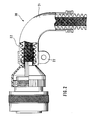
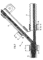
- a fitting is shown as a connection between a cable harness 2 and a connector 3 in the form of an elbow 1, which consists of two half-shells 4 and 5.
- the parting line of both half-shells 4, 5 lies in the area of the image plane.
- the half-shell 4 lying below the image plane is visible in the regions shown broken away, while the upper half-shell 5 appears in the view in the region not shown broken.
- the elbow 1 has an overlap area 7 with the protective tube 6. Within a clamping area 8, the elbow 1 is connected to the sheath 6 by means of a cable tie 9.
- the cable harness 2 is protected from the protective hose 6 by an additional braid 12.
- the protective tube 6 is designed as a corrugated tube and has alternating circumferential beads and grooves on its outer surface, the spacing of which is determined by a predetermined pitch.
- a circumferential bead 10 is arranged on the part of the manifold 1, which in a groove of the Protective hose 6 engages.
- a fastening part 15 is arranged so that one end protrudes into the overlap area 8 and engages with an inner bead 13 in a groove of the protective tube 6.
- This fastening part 15 has further inner beads at regular intervals adapted to the casing 6. The transition from the fastening part 15 to the plug connector 3 forms a transition part 16.
- the fastening part 15 like the manifold 1, also consists of two half-shells, which are also held together by a tensioning element. In contrast to the half shells 4, 5 of the manifold 1, these two half shells are identical parts. Here the tensioning element is realized by a tensioning clamp 18. At the free end of the elbow 1, this is clamped together by a further cable tie 11. The fact that the manifold 1 consists of two half shells 4, 5, this can be easily dismantled and renewed in an already installed wiring harness 2.
- the fastening part is connected here in one piece to the manifold 20. This further reduces the number of individual parts required.
- a calf binder and two half-shells are omitted.
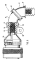
- an elbow 30 is composed of two elbows 31 and 32.
- This manifold 30 and the fastening part 33 each consist of two half-shells.
- the connection of the fastening part 33 to the transition part 36 is designed as described above.
- the fastening part 33 has a flange 34 to which one end of the elbow 31 is adapted and a groove 35 is provided.
- the manifold 32 is connected to the manifold 31.
- the arrangement is fixed by cable ties 37 or a clamp 38.
- the half-shells of the elbows 31 and 32 are identical parts. As a result of the assemblability, different manifold shapes can also be produced in modular form.
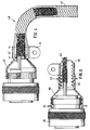
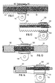
- FIG. 4 shows an elbow 40 for an end housing 41 consisting of two half-shells.
- the protective tube is designed here as a braid 42 and is drawn from the outside over the elbow 40.
- the braid 42 is fastened in the clamping area 43 by a clamp 44.
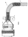
- FIG. 5 Another manifold 50 for an end housing 51 is shown in FIG. 5.
- the manifold 50 again consists of two half-shells and the protective tube is designed as a braid 52.
- the braid 52 is guided on the inside through the elbow 50 and the fastening takes place in a clamping area 53 by means of a clamp 54, the braid 52 being put out over the end of the elbow 50.
- a shaped piece is designed in the form of an end housing 60, a protective tube 61 of a cable harness 62 being connected to a plug connector 63.
- the end housing 60 in turn consists of two half-shells, the clamping elements being designed as snap rings 64, 65.
- Corrugated hoses 71, 72, 73 are used as the protective hose, the distributor piece 70 being of two parts and being adapted in the clamping regions 74, 75, 76 to the shape of the corrugated hoses 71, 72, 73.
- Single earrings 77, 78, 79 serve as tensioning elements.
- corrugated hoses 71, 72, 73 it is of course also possible to use corrugated hoses or spiral hoses.
- a further distributor piece 80 as a two-part shaped piece can be seen from FIG. 8.
- Braids 81, 82, 83 are used here as the protective hose, which are pulled over the distributor piece 80 in the clamping areas 84, 85, 86 and are fixed via tensioning elements in the form of single-ear rings 87, 88, 89.
- Fig. 9 shows a formed as a two-part distributor 90, wherein braids 91, 92, 93 are also used as a protective tube.
- the halves of the distributor piece 90 are connected to one another by means of tensioning elements which are designed as cable ties 94, 95, 96.
- the ends of the braids 91, 92, 93 are combed out and are connected to one another by means of crimp connector 97.
- a solder sleeve can also be used.
- a shaped piece as a sleeve 100 is shown in FIG. 10 and serves to connect two corrugated hoses 101, 102.
- the sleeve 100 consists of two half-shells 103, 104, the inner surfaces of which are adapted to the shape of the corrugated hoses 101, 102.
- An embodiment, not shown, is that a shrink ring is used instead of the crimp ring 105.
- 11 as a sleeve 110 consists of two half-shells 112, 113, the inner surfaces of which are adapted to the shape of a corrugated hose 111.
- a discharge clamp 114 is provided for the electrical connection of the corrugated hose 111, so that a connection can be established between the hose 111 and the ground.
- FIG. 12 shows a shaped piece which is designed as an end fastening 120 and serves to fix the end of a corrugated hose 121.
- the shaped piece 120 consists of two half-shells 122, 123 which are placed on the end of the hose 121 and are clamped by means of a clamp 124. This also makes it possible to establish an electrical connection between the hose 121 and the ground.
- the sleeve 130 is designed as a sleeve 130 and serves for the mechanical and electrical connection of two braids 131, 132 and at the same time for establishing a ground connection by means of a diverter clip 135.
- the sleeve 130 consists of two half-shells 133, 134, over which the braids 131, 132 are pushed and fastened by means of the clamp 135.
- FIG. 14 shows a shaped piece which is designed as an end fastening 140 and serves to fix the end of a braid 141.
- the shaped piece 140 consists of two half-shells 142, 143, over which the end of the braid 141 is pushed and fastened by means of a clamp 144. An electrical connection between the braid 141 and ground can thus also be established.
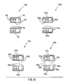
- half-shell pairs 150, 150a, 150b and 150c which can be used to produce a sleeve, a discharge point or a final attachment.
- the inner surfaces of these half-shell pairs are adapted to a corrugated hose.
- the half-shells 150 and 151 have four beads 153 and 154, respectively. Deviating from the wave shape given by the profile of the corrugated hose, these beads 153, 154 all show a cross-section which is bevelled to the right (sawtooth profile).
- the inner surfaces of the half-shell pair 150a have four beads 153a and 154b. Each of these beads shows a sawtooth shape that is bevelled to the left.
- the inner surfaces of the half-shell pair 150c have four ridges 153b and 154b. Here the beads are bevelled to the left and to the right at the same time, thus showing an acute cross-sectional shape.
- the inner surfaces of the half-shell pair 150c have four beads 153c, 154c, 155c and 156c. These beads alternately show a cross-sectional shape that is tapered to the left and then to the right.
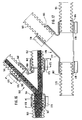
- a distributor piece 160 consisting of two half-shells shaped piece similar to FIG. 7 is shown in FIG. 16.
- Corrugated hoses 161, 162, 163 are used as the protective hose. Outside grooves 164, 165 and 166 are arranged at the free ends of the distributor piece, into which corresponding inner beads of fastening parts 167, 168 and 169 engage.
- the inner surfaces of the fastening parts 167, 168 and 169 are adapted in the clamping areas 170, 171 and 172 to the shape of the corrugated hoses 161, 162, 163.
- the fastening parts 167, 168 and 169 each consist of two half-shells, as described for example in connection with FIG. 1 or 15.
- Single earrings 173, 174 and 175 serve as clamping elements.
- a further embodiment of a distributor piece 176 consisting of two half-shells with only the lower half-shell 177 is shown. Both half-shells are stretched by one-ear clamps 178 onto the respective end of a hose 179, 180, 181.
- the half-shells also have a smooth cylindrical shape in the area of overlap with the hoses 179, 180, 181, but a flange 182, 183, 184 engaging in a groove of the hose profile is provided at the respective end of the shell.
- the hoses are secured in the axial direction with respect to the half-shells.
- the tight fit of the connection results from tightening the one-ear clips 178.
- the smooth shape of the half-shells mentioned offers advantages in their manufacture and assembly.
- the aforementioned fittings can be made from different materials. Their selection depends on the purpose of the respective cover. If the sleeves in question are used, for example, to mechanically protect a cable harness, sleeves made of plastic are provided. In this case, it is sufficient, if appropriate Moldings made of plastic. If the cable harness is to be shielded against electromagnetic influences, the relevant sheath, hose or braid is made of a suitable metal. In these cases, certain parts of the shaped pieces must also be electrically conductive and are therefore expediently made from metal or from an electrically conductive plastic. To protect a cable harness against current peaks caused by lightning strikes, it must be provided with discharge points at certain points in the areas at risk from lightning strikes.
Landscapes
- Engineering & Computer Science (AREA)
- Architecture (AREA)
- Civil Engineering (AREA)
- Structural Engineering (AREA)
- Details Of Indoor Wiring (AREA)
- Supports For Pipes And Cables (AREA)
Claims (14)
- Pièce de forme pour le guidage directionnel d'un tube de protection de conduite (6, 42, 91, 92, 93, 111, 121, 141), métallique souple telle que les faisceaux de câble ou analogues, notamment pour les applications à bord d'un avion, pour la protection contre les influences magnétiques, la pièce de forme (1, 20, 30, 40, 50, 90, 110, 120, 140) se composant de deux demi-coquilles (4, 5, 21, 22, 112, 113, 122, 123, 142, 143) à plan de joint au niveau du plan de symétrie, les coquilles (4, 5, 21, 22, 112, 113, 122, 123, 142, 143) étant reliées ensemble par au moins un élément de serrage (9, 11, 23, 37, 44, 54, 94, 95, 96, 114, 124, 144), pièce caractérisée en ce que le tube de protection, continu (6, 42, 91, 92, 93, 111, 121, 141) est entouré par les deux demi-coquilles (4, 5, 21, 22, 112, 113, 122, 123, 142, 143) et leurs surfaces intérieures dans la zone de serrage sont réalisées en correspondance avec le tube de protection (6, 42, 91, 92, 93, 111, 121, 141) en forme de tube ondulé, qu'elles reçoivent, de façon qu'au moins un bourrelet (10) soit logé en appui.
- Pièce de forme selon la revendication 1, caractérisée en ce qu'elle entoure extérieurement le tube de protection (6, 42, 52) et est réalisée sous la forme d'un coude (1, 20, 30, 40, 50).
- Pièce de forme selon la revendication 2, caractérisée en ce que le coude (31) comporte une bride pour le raccordement à un autre coude (32).
- Pièce de forme selon la revendication, caractérisée en ce qu'elle est réalisée sous la forme d'une pièce de distribution (90) qui entoure extérieurement le tube de protection (91, 92, 93).
- Pièce de forme selon la revendication 1, caractérisée en ce qu'elle entoure de l'extérieur le tube de protection (111, 121, 141) et est réalisée de manière linéaire.
- Pièce de forme selon l'une des revendications 1 à 5, caractérisée en ce que sa surface intérieure est en forme de dents de scie (153, 154) dans la zone de serrage.
- Pièce de forme selon la revendication 1, caractérisée en ce qu'elle peut s'introduire de l'intérieur dans le tube de protection réalisé en forme de tresse (42) pour être reliée à celui-ci à l'aide d'un élément de serrage (44).
- Pièce de forme selon l'une des revendications 1 à 7, caractérisée en ce que l'élément de serrage est réalisé sous forme d'organe de liaison de câble (9, 11, 94, 95, 96).
- Pièce de forme selon l'une des revendications 1 à 7, caractérisée en ce que l'élément de serrage est réalisé sous forme de collier (23, 44, 54).
- Pièce de forme selon l'une des revendications 1 à 9, caractérisée en ce que l'élément de serrage est réalisé sous forme de bague élastique (64, 65).
- Pièce de forme selon l'une des revendications 1 à 7, caractérisée en ce que l'élément de serrage est réalisé sous forme de bague sertie (105).
- Pièce de forme selon l'une des revendications 1 à 7, caractérisée en ce que l'élément tendeur est réalisé sous forme de bague rétractable.
- Pièce de forme selon l'une des revendications 1 à 7, caractérisée en ce que l'élément tendeur est réalisé sous forme de pince à oreille (44, 45).
- Pièce de forme selon l'une des revendications 1 à 7, caractérisée en ce que les demi-coquilles (122, 123) ont une paroi lisse et une partie rabattue à l'extrémité, pénétrant dans les ondulations du tube profilé.
Applications Claiming Priority (2)
| Application Number | Priority Date | Filing Date | Title |
|---|---|---|---|
| DE19893914933 DE3914933C1 (fr) | 1989-05-06 | 1989-05-06 | |
| DE3914933 | 1989-05-06 |
Publications (3)
| Publication Number | Publication Date |
|---|---|
| EP0396927A2 EP0396927A2 (fr) | 1990-11-14 |
| EP0396927A3 EP0396927A3 (fr) | 1992-06-03 |
| EP0396927B1 true EP0396927B1 (fr) | 1994-11-30 |
Family
ID=6380213
Family Applications (1)
| Application Number | Title | Priority Date | Filing Date |
|---|---|---|---|
| EP19900107049 Expired - Lifetime EP0396927B1 (fr) | 1989-05-06 | 1990-04-12 | Elément de connexion, respectivement de liaison pour harnais de câbles |
Country Status (2)
| Country | Link |
|---|---|
| EP (1) | EP0396927B1 (fr) |
| DE (1) | DE3914933C1 (fr) |
Cited By (1)
| Publication number | Priority date | Publication date | Assignee | Title |
|---|---|---|---|---|
| DE102007009015A1 (de) * | 2007-02-23 | 2008-09-04 | Continental Automotive Gmbh | Kabelhalteanordnung |
Families Citing this family (4)
| Publication number | Priority date | Publication date | Assignee | Title |
|---|---|---|---|---|
| DE9017012U1 (de) * | 1990-12-17 | 1991-04-11 | Deutsche Aerospace Airbus Gmbh, 21129 Hamburg | Formstück zum Verbinden flexibler Leitungsschutzschläuche |
| DE4206016C2 (de) * | 1992-02-27 | 1994-02-10 | Deutsche Aerospace Airbus | Anschlußelement zur Halterung eines Schutzschlauches |
| DE4425867C2 (de) * | 1994-07-21 | 1999-06-10 | Daimler Chrysler Aerospace | Komponente eines Schutzschlauchsystems mit einem Endgehäuse |
| EP2708703B1 (fr) * | 2012-09-12 | 2021-03-10 | General Electric Company | Dispositif de montage et son procédé d'assemblage |
Family Cites Families (6)
| Publication number | Priority date | Publication date | Assignee | Title |
|---|---|---|---|---|
| FR705884A (fr) * | 1930-11-18 | 1931-06-16 | Raccord pour tubes, câbles, et autres applications | |
| FR1142856A (fr) * | 1956-03-09 | 1957-09-24 | Etirage Et Laminage Du Nord Et | Raccord pour tubes métalliques |
| GB1337242A (en) * | 1970-11-14 | 1973-11-14 | Celmac Plasclip Ltd | Couplings for conduits |
| US3711632A (en) * | 1971-12-02 | 1973-01-16 | Gen Motors Corp | End fitting for corrugated conduit |
| US4173386A (en) * | 1978-03-13 | 1979-11-06 | W. L. Gore & Associates, Inc. | Coaxial assembly |
| US4671598A (en) * | 1985-09-25 | 1987-06-09 | Schiller Industries Inc. | Backshell connector for multi-conductor shielded cables |
-
1989
- 1989-05-06 DE DE19893914933 patent/DE3914933C1/de not_active Expired - Fee Related
-
1990
- 1990-04-12 EP EP19900107049 patent/EP0396927B1/fr not_active Expired - Lifetime
Cited By (1)
| Publication number | Priority date | Publication date | Assignee | Title |
|---|---|---|---|---|
| DE102007009015A1 (de) * | 2007-02-23 | 2008-09-04 | Continental Automotive Gmbh | Kabelhalteanordnung |
Also Published As
| Publication number | Publication date |
|---|---|
| EP0396927A3 (fr) | 1992-06-03 |
| DE3914933C1 (fr) | 1990-10-18 |
| EP0396927A2 (fr) | 1990-11-14 |
Similar Documents
| Publication | Publication Date | Title |
|---|---|---|
| DE2828893C2 (de) | Rohrverbinder für Kabelschutzrohre | |
| DE69815744T2 (de) | Rotierende Erdungskupplung zum äusseren Erden von Gehäusen | |
| DE3640226C2 (fr) | ||
| EP3152809B1 (fr) | Appareil électrique | |
| DE3914929C2 (fr) | ||
| DE102010017266A1 (de) | Elektrische Verteilereinrichtung | |
| EP1524731B1 (fr) | Boîtier de connecteur avec étanchéité améliorée pour câble | |
| DE202006003590U1 (de) | Beheizbarer Wellschlauch | |
| DE8718055U1 (de) | Mehradriges Schwachstromkabel, insbesondere für elektrohydraulische Ausbausteuerungen | |
| EP0396927B1 (fr) | Elément de connexion, respectivement de liaison pour harnais de câbles | |
| DE69304088T2 (de) | Abgeschirmte Verbindung vorbereitet für die Montage eines Verbinders | |
| DE19605979C2 (de) | Strom-tragfähiges Verbindungselement für Rohrleitungen einer gasisolierten Schaltanlage | |
| DE3626403A1 (de) | Anschlussarmatur | |
| DE4215432A1 (de) | Kupplung fuer umflochtene kabel | |
| EP0397062A2 (fr) | Dispositif pour la protection d'installations électriques | |
| EP4268335A1 (fr) | Bouchon destiné à être fixé sur des conduites et d'autres éléments allongés | |
| EP3561976B1 (fr) | Boîte d'installation | |
| DE9103511U1 (de) | Vorrichtung zum Verbinden von Rohren | |
| DE3034415A1 (de) | Kupplungsteil einer elektrischen steckverbindung | |
| DE3738203C2 (fr) | ||
| DE2300627A1 (de) | Schlauchleitung mit signalleitungsdurchfuehrung | |
| DE19812635C2 (de) | Elektrische Einrichtung | |
| EP2194308B1 (fr) | Pièce de couplage pour pièces de raccordement de tuyau annelé | |
| DE19539279C2 (de) | Befestigungselement zum Fixieren von flexiblen Schutzschläuchen | |
| DE9011112U1 (de) | Elektrische Kabelanordnung |
Legal Events
| Date | Code | Title | Description |
|---|---|---|---|
| PUAI | Public reference made under article 153(3) epc to a published international application that has entered the european phase |
Free format text: ORIGINAL CODE: 0009012 |
|
| AK | Designated contracting states |
Kind code of ref document: A2 Designated state(s): FR GB |
|
| RAP1 | Party data changed (applicant data changed or rights of an application transferred) |
Owner name: DEUTSCHE AIRBUS GMBH |
|
| PUAL | Search report despatched |
Free format text: ORIGINAL CODE: 0009013 |
|
| AK | Designated contracting states |
Kind code of ref document: A3 Designated state(s): FR GB |
|
| 17P | Request for examination filed |
Effective date: 19920623 |
|
| RAP1 | Party data changed (applicant data changed or rights of an application transferred) |
Owner name: DEUTSCHE AEROSPACE AIRBUS GMBH |
|
| 17Q | First examination report despatched |
Effective date: 19930916 |
|
| GRAA | (expected) grant |
Free format text: ORIGINAL CODE: 0009210 |
|
| STAA | Information on the status of an ep patent application or granted ep patent |
Free format text: STATUS: THE PATENT HAS BEEN GRANTED |
|
| AK | Designated contracting states |
Kind code of ref document: B1 Designated state(s): FR GB |
|
| GBT | Gb: translation of ep patent filed (gb section 77(6)(a)/1977) |
Effective date: 19941212 |
|
| ET | Fr: translation filed | ||
| PGFP | Annual fee paid to national office [announced via postgrant information from national office to epo] |
Ref country code: GB Payment date: 19950403 Year of fee payment: 6 |
|
| RAP2 | Party data changed (patent owner data changed or rights of a patent transferred) |
Owner name: DAIMLER-BENZ AEROSPACE AIRBUS GESELLSCHAFT MIT BES |
|
| PGFP | Annual fee paid to national office [announced via postgrant information from national office to epo] |
Ref country code: FR Payment date: 19950530 Year of fee payment: 6 |
|
| PLBE | No opposition filed within time limit |
Free format text: ORIGINAL CODE: 0009261 |
|
| 26N | No opposition filed | ||
| PG25 | Lapsed in a contracting state [announced via postgrant information from national office to epo] |
Ref country code: GB Effective date: 19960412 |
|
| GBPC | Gb: european patent ceased through non-payment of renewal fee |
Effective date: 19960412 |
|
| PG25 | Lapsed in a contracting state [announced via postgrant information from national office to epo] |
Ref country code: FR Effective date: 19961227 |
|
| REG | Reference to a national code |
Ref country code: FR Ref legal event code: ST |