EP0396702B1 - Elastische kniegelenkbandage - Google Patents
Elastische kniegelenkbandage Download PDFInfo
- Publication number
- EP0396702B1 EP0396702B1 EP89912403A EP89912403A EP0396702B1 EP 0396702 B1 EP0396702 B1 EP 0396702B1 EP 89912403 A EP89912403 A EP 89912403A EP 89912403 A EP89912403 A EP 89912403A EP 0396702 B1 EP0396702 B1 EP 0396702B1
- Authority
- EP
- European Patent Office
- Prior art keywords
- knee
- cap
- strand
- insert
- profile insert
- Prior art date
- Legal status (The legal status is an assumption and is not a legal conclusion. Google has not performed a legal analysis and makes no representation as to the accuracy of the status listed.)
- Expired - Lifetime
Links
Images

Classifications
-
- A—HUMAN NECESSITIES
- A61—MEDICAL OR VETERINARY SCIENCE; HYGIENE
- A61F—FILTERS IMPLANTABLE INTO BLOOD VESSELS; PROSTHESES; DEVICES PROVIDING PATENCY TO, OR PREVENTING COLLAPSING OF, TUBULAR STRUCTURES OF THE BODY, e.g. STENTS; ORTHOPAEDIC, NURSING OR CONTRACEPTIVE DEVICES; FOMENTATION; TREATMENT OR PROTECTION OF EYES OR EARS; BANDAGES, DRESSINGS OR ABSORBENT PADS; FIRST-AID KITS
- A61F5/00—Orthopaedic methods or devices for non-surgical treatment of bones or joints; Nursing devices ; Anti-rape devices
- A61F5/01—Orthopaedic devices, e.g. long-term immobilising or pressure directing devices for treating broken or deformed bones such as splints, casts or braces
- A61F5/0102—Orthopaedic devices, e.g. long-term immobilising or pressure directing devices for treating broken or deformed bones such as splints, casts or braces specially adapted for correcting deformities of the limbs or for supporting them; Ortheses, e.g. with articulations
- A61F5/0104—Orthopaedic devices, e.g. long-term immobilising or pressure directing devices for treating broken or deformed bones such as splints, casts or braces specially adapted for correcting deformities of the limbs or for supporting them; Ortheses, e.g. with articulations without articulation
- A61F5/0106—Orthopaedic devices, e.g. long-term immobilising or pressure directing devices for treating broken or deformed bones such as splints, casts or braces specially adapted for correcting deformities of the limbs or for supporting them; Ortheses, e.g. with articulations without articulation for the knees
- A61F5/0109—Sleeve-like structures
-
- A—HUMAN NECESSITIES
- A61—MEDICAL OR VETERINARY SCIENCE; HYGIENE
- A61F—FILTERS IMPLANTABLE INTO BLOOD VESSELS; PROSTHESES; DEVICES PROVIDING PATENCY TO, OR PREVENTING COLLAPSING OF, TUBULAR STRUCTURES OF THE BODY, e.g. STENTS; ORTHOPAEDIC, NURSING OR CONTRACEPTIVE DEVICES; FOMENTATION; TREATMENT OR PROTECTION OF EYES OR EARS; BANDAGES, DRESSINGS OR ABSORBENT PADS; FIRST-AID KITS
- A61F13/00—Bandages or dressings; Absorbent pads
- A61F13/06—Bandages or dressings; Absorbent pads specially adapted for feet or legs; Corn-pads; Corn-rings
- A61F13/061—Bandages or dressings; Absorbent pads specially adapted for feet or legs; Corn-pads; Corn-rings for knees
-
- A—HUMAN NECESSITIES
- A61—MEDICAL OR VETERINARY SCIENCE; HYGIENE
- A61F—FILTERS IMPLANTABLE INTO BLOOD VESSELS; PROSTHESES; DEVICES PROVIDING PATENCY TO, OR PREVENTING COLLAPSING OF, TUBULAR STRUCTURES OF THE BODY, e.g. STENTS; ORTHOPAEDIC, NURSING OR CONTRACEPTIVE DEVICES; FOMENTATION; TREATMENT OR PROTECTION OF EYES OR EARS; BANDAGES, DRESSINGS OR ABSORBENT PADS; FIRST-AID KITS
- A61F5/00—Orthopaedic methods or devices for non-surgical treatment of bones or joints; Nursing devices ; Anti-rape devices
- A61F5/01—Orthopaedic devices, e.g. long-term immobilising or pressure directing devices for treating broken or deformed bones such as splints, casts or braces
- A61F5/0102—Orthopaedic devices, e.g. long-term immobilising or pressure directing devices for treating broken or deformed bones such as splints, casts or braces specially adapted for correcting deformities of the limbs or for supporting them; Ortheses, e.g. with articulations
- A61F2005/0132—Additional features of the articulation
- A61F2005/0172—Additional features of the articulation with cushions
- A61F2005/0176—Additional features of the articulation with cushions supporting the patella
Definitions
- the invention relates to an elastic knee brace in the form of a tube with an elastic profile insert that encompasses the kneecap in a recess.
- Such a knee brace is known from DE-PS 34 12 772.
- This bandage contains a profile insert that partially engages the knee joint on both sides with extension flaps, with reinforcement pieces being built into the extension flaps. These reinforcement pieces are intended to exert a radially acting pressure on the knee joint from both sides.
- the profile insert is provided on one side with a bead-like elevation near the recess for the patella, which likewise increases the pressure on the knee in its place.
- the kneecap should thereby be able to be displaced both inwards and in the direction of the outside of the knee. A static effect of the pressure exerted on the knee by the increase is thus used.
- a knee joint bandage with the tendency to medially shift the kneecap has become known from DE-U-81 15 670.7.
- This bandage contains a C-shaped profile insert (patella pad), the open side of which is arranged medially (inside the leg).
- the knee joint bandage, into which the profile insert is either woven or sewn in, consists of two sheath halves, of which the medial sheath half is designed in a tighter weave than the outer (lateral) sheath half.
- the purpose of this knee joint bandage is to relieve used retropatellar cartilage surfaces and at the same time to relieve unused cartilage surfaces.
- the profile insert should always be pulled elastically against the lateral side of the kneecap (see description page 5 last sentence), in particular also movements of the knee joint. That this effect actually occurs with the only C-shaped profile insert due to the different tightness of the weave of the two sleeve halves is not readily apparent, because when the knee joint bandage is applied, the sleeve sleeve must adapt to the respective shape of the knee joint, whereby the The longitudinal expansion of the weakly woven shell halves is essentially determined by the elongation of the more woven shell halves.
- the invention has for its object to act dynamically on a kneecap, which is either pathological from its ideal position or displaced on the calf side as a very common standard variant, when the knee joint is flexed and thereby to correct the position of the kneecap.
- a flexible, non-stretchable tendon is embedded in the profile insert in a fixed connection with it, which connects the areas of the profile insert adjacent to the patella poles and on the calf side in the arch around the patella in such a way that when the distance of these areas is increased when Bending the knee joint the distance of the arch from the connecting line of the patella poles and is reduced and the relevant edge of the Aiisspartechnik the profile insert on the adjacent side of the patella presses this medially displacing and centering.
- the front of the knee is stretched considerably over the kneecap.
- This stretch is transferred to the profile insert, which is an integral part of the knee joint bandage, so that the regions of the profile insert, which are adjacent to the knee cap poles, move away from one another with respect to the extended position of the knee joint. Due to this increase in distance, a pull is practically exerted on the ends of the tendon, so that this is pulled in its central region to the relevant side of the patella.
- the edge of the air saving in the profile insert which contains the tendon, exerts a lateral pressure on the kneecap, which consequently increases with the bending of the knee is pulled towards the kneecap.
- the tendon is embedded as a non-stretchable, bendable strand, directly next to the edge of the profile insert on the patella face, the patella at least from the upper to the lower patella pole, in the profile insert in a firm bond with it. Due to this position of the strand, this exerts a direct influence on the patella in its function.
- the ends of the strand can be shaped into anchors in the material of the profile insert, that on the side of the connecting line between the patella poles facing away from the arc of the strand lie.
- These anchors can advantageously be designed as loops, but it is also possible to provide thickenings of the strand as anchors.
- Another possibility of creating the firm bond of the strand with the profile insert is to provide the strand over its length with recesses which are filled with the material of the profile insert.
- the penetration of the material of the profile insert into the recesses ensures that every point along the tendon remains firmly connected to the surrounding material of the profile insert when the profile insert is stretched over the bent knee.
- FIG. 1 shows the thigh 1 and the lower leg 2 and the knee joint 3 of a human leg, the shin 4 and the fibula 5 being shown in the lower leg 2.
- the knee joint bandage 6, which is made of an elastic textile, is pulled over the knee joint 3 and fits tightly around the knee joint 3 and the relevant places on the thigh 1 and the lower leg 2.
- the profile insert 7 described in more detail with reference to FIGS. 3 and 4 is embedded, which forms a cushion consisting of elastic material.
- B. silicone rubber can be used in a known manner.
- the profile insert 7 is provided in the region of the kneecap, not shown here, with the recess 8, which closely surrounds the kneecap.
- the strand 9 acting as a tendon is embedded, the z. B. can be designed as a wire rope.
- the strand is thus bendable but not stretchable, which means that it is able to follow deformations of the profile insert 7 without being lengthened.
- the strand 9 is provided with the loops 10 and 11, which give the strand 9 a secure anchoring in the profile insert 7, which will be discussed in more detail in connection with FIGS. 3 and 4.
- the profile insert 7 is expediently incorporated into the knee joint bandage 6 during the production thereof, but it is also possible to glue or weld the profile insert onto the bandage.
- the profile insert 7 is an integral part of the knee joint bandage 6 in the sense that when the knee 3 is flexed, both the knee joint bandage 6 and the profile insert 7 join in this movement without it being between the knee joint bandage 6 and the Profile insert 7 can come to a shift.
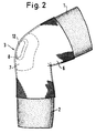
- FIG. 2 shows the same knee brace 6 with the profile insert 7 contained therein with the knee 3 bent.
- the profile insert 7 is in the region of the recess 8 the kneecap 12 indicated in dash-dotted lines.
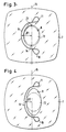
- FIGS. 3 and 4 show the profile insert 7 in a flat development, specifically according to FIG. 3 in relation to the extended knee (see FIG. 1) and FIG. 4 in relation to the bent knee (see FIG. 2).
- the patella 12 is also shown in dash-dotted lines in Figures 3 and 4.
- the profile insert 7 according to FIG. 3 contains the strand 9 with the two loops 10 and 11 serving as anchors.
- the center line 15, which runs over the poles 13 and 14 of the patella 12 is drawn in, the distance D1 from the arc of the strand 9 adheres to.
- This bow wraps around the patella 12 on the side of the fibula 5 (in FIG. 1) within the material of the profile insert 7 and then extends beyond the center line 15, where the strand 9 then forms the loops 10 and 11, as said.
- the position of the kneecap 12 and the profile insert 7 shown in FIG. 3 represents the normal position of the knee cap 12 for the patient concerned - as a standard variant, however, it is already slightly outside the ideal position - together with the profile insert 7 surrounding the knee cap 12.
- the knee joint bandage 6 and the profile insert 7 anchored therein are stretched on the outside of the knee joint 3, which leads to the recess 8 extends in the direction of the center line 15, taking on an oval shape.
- the profile insert 7 is drawn in the flat development. Since the strand 9 now consists of inextensible material and is firmly anchored in the material of the profile insert 7, the areas of the strand 9 in front of the loops 10 and 11 in the direction of the center line 15 pulled apart, which because of the inextensibility of the strand 9 has the result that it moves towards the center line 15 in its arc region.
- the distance of the arc region of the strand 9 to the center line 15 is thus reduced to the length D2.
- the profile insert 7 together with the knee brace 6 remains in place in principle because of the fixed clamping of the knee joint 3, so that the reduction in the distance between the arch region of the strand 9 and the center line 15 from length D1 to length D2 has such an effect that the edge 19 of the recess 8 presses from the side against the relevant edge of the patella 12 and moves it towards the inside of the leg.
- the degree of this shift depends on the angle of the flexion of the knee joint 3.
- FIG. 4 shows that it shows the ratios on a scale of 1: 1.
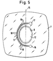
- FIG. 5 shows a variant of the method of anchoring the strand 9 in the profile insert 7.
- the strand 9 is provided over its length with a plurality of braces 18 with which the strand 9 penetrates into the material of the profile insert 7 and thus one additional, possibly also sufficient anchoring.
- the anchoring of the strand 9 over its length z. B. can also be brought about in that the strand is provided with recesses, for example in the form of holes, which are then filled by the material of the profile insert 7. In this case, a ladder-like perforated plastic tape is expediently used as the strand.
Landscapes
- Health & Medical Sciences (AREA)
- Engineering & Computer Science (AREA)
- Biomedical Technology (AREA)
- Heart & Thoracic Surgery (AREA)
- Vascular Medicine (AREA)
- Life Sciences & Earth Sciences (AREA)
- Animal Behavior & Ethology (AREA)
- General Health & Medical Sciences (AREA)
- Public Health (AREA)
- Veterinary Medicine (AREA)
- Nursing (AREA)
- Orthopedic Medicine & Surgery (AREA)
- Orthopedics, Nursing, And Contraception (AREA)
Abstract
Description
- Die Erfindung bezieht sich auf eine elastische Kniegelenkbandage in Schlauchform mit einer elastischen, die Kniescheibe in einer Aussparung umfassenden Profileinlage.
- Eine derartige Kniegelenkbandage ist aus der DE-PS 34 12 772 bekannt. Diese Bandage enthält eine beidseitig mit Verlängerungslappen das Kniegelenk teilweise anfassende Profileinlage, wobei in die Verlängerungslappen Verstärkungsstücke eingebaut sind. Mit diesen Verstärkungsstücken soll auf das Kniegelenk von beiden Seiten ein radial wirkender Druck ausgeübt werden. Bei einer weiteren in der Druckschrift beschriebenen Ausführungsform ist die Profileinlage einseitig mit einer wulstförmigen Erhöhung in der Nähe der Aussparung für die Kniescheibe versehen, die ebenfalls an ihrer Stelle den Druck auf das Knie erhöht. Wie in der zugehörigen Beschreibung ausgeführt ist, soll hierdurch die Kniescheibe sowohl nach innen als auch in Richtung auf die Außenseite des Knies verschoben werden können. Ausgenutzt wird dabei also eine statische Wirkung des durch die Erhöhung ausgeübten Druckes auf das Knie.
- Es ist weiterhin in der US-PS 44 45 505 eine elastische Kniegelenkbandage beschrieben, die mit einer Aussparung für die Kniescheibe versehen ist und in die Polster eingebaut sind, durch deren Lage eine seitliche Verschiebung der Kniescheibe verhindert werden soll. Um die Wirkung dieser Polster zu intensivieren, ist die Kniegelenkbandage mit elastischen Bändern versehen, die mittels Klettverschlüssen um die Bandage gespannt werden können, wodurch die Lage der Polster gesichert werden soll. Es handelt sich bei dieser Kniegelenkbandage also ebenfalls um eine durch statisch wirkenden Druck ausgeübte Einwirkung auf die Kniescheibenposition.
- Eine Kniegelenkbandage mit der Tendenz der medialen Verschiebung der Kniescheibe ist aus dem DE-U-81 15 670.7 bekannt geworden. Diese Bandage enthält eine C-förmige Profileinlage (Patellapelotte), deren offene Seite medial (beineinwärtig) angeordnet ist. Die Kniegelenkbandage, in die die Profileinlage entweder eingewebt oder eingenäht ist, besteht aus zwei Hüllenhälften, von denen die mediale Hüllenhälfte in strafferer Webart als die beinauswärtigen (laterale) Hüllenhälfte ausgebildet ist. Dieser Kniegelenkbandage liegt die Aufgabe zugrunde, eine Entlastung von verbrauchten retropatellaren Knorpelflächen und zugleich eine Umbelastung auf unverbrauchte Knorpelflächen zu bewirken. Wegen der strafferen Webart der lateralen Hüllenhälfte soll die Profileinlage ständig elastisch gegen die laterale Seite der Kniescheibe gezogen werden (siehe Beschreibungsseite 5 letzter Satz), insbesondere auch Bewegungen des Kniegelenks. Daß dieser Effekt bei der nur C-förmig ausgebildeten Profileinlage aufgrund der unterschiedlichen Straffheit der Webart der beiden Hüllenhälften tatsächlich eintritt, ist nicht ohne weiteres ersichtlich, denn bei angelegter Kniegelenkbandage muß sich diese mit ihren beiden Hüllenhälften an die jeweilige Form des Kniegelenks anpassen, wobei die Längsdehnung der schwächer gewebten Hüllenhälften von der Dehnung der stärker gewebten Hüllenhälfte im wesentlichen bestimmt wird. Daß es bei der Gestaltung dieser bekannten Kniegelenkbandage im wesentlichen auf einen ständigen Druck gegen die laterale Seite der Kniescheibe ankommt, geht auch aus einem weiteren in der Druckschrift behandelten Ausführungsbeispiel hervor, wonach an die beiden Enden der C-förmigen Profileinlage ein die Kniegelenkbandage über ihre rückwärtige Seite umfassendes Spannband ansetzt, das vom Benutzer auf eine gewünschte ständige Spannung eingestellt werden kann.
- Der Erfindung liegt die Aufgabe zugrunde, auf eine Kniescheibe, die aus ihrer Idealposition entweder krankhaft oder als sehr häufige Normvariante wadenbeinseitig verschoben ist, beim Beugen des Kniegelenks dynamisch einzuwirken und dabei die Kniescheibenlage zu korrigieren. Erfindungsgemäß geschieht dies dadurch, daß in die Profileinlage in festem Verbund mit dieser ein biegsames, nicht dehnbares Spannglied eingelagert ist, das die Bereiche der Profileinlage benachbart zu den Kniescheibenpolen und wadenbeinseitig im Bogen um die Kniescheibe derart verbindet, daß bei Vergrößerung der Entfernung dieser Bereiche beim Beugen des Kniegelenks der Abstand des Bogens von der Verbindungslinie der Kniescheibenpole und verringert wird und der betreffende Rand der Aiissparung der Profileinlage auf die benachbarte Seite der Kniescheibe diese medial verschiebend und zentrierend drückt.
- Beim Beugen des Kniegelenks wird diese Kniegelenkbandage an ihrer Vorderseite über die Kniescheibe beträchtlich gedehnt. Diese Dehnung überträgt sich auf die Profileinlage, die ein integraler Bestandteil der Kniegelenkbandage ist, so daß sich die Bereiche der Profileinlage, die den Kniescheibenpolen benachbart sind, voneinander gegenüber der Strecklage des Kniegelenks entfernen. Aufgrund dieser Vergrößerung der Entfernung wird auf die Enden des Spanngliedes gewissermaßen ein Zug ausgeübt, so daß dieses in seinem mittleren Bereich an die betreffende Seite der Kniescheibe herangezogen wird. Hierbei übt der das Spannglied enthaltene Rand der Aiissparung in der Profileinlage einen seitlichen Druck auf die Kniescheibe aus, die somit zunehmend mit der Beugung des Knies an die Kniescheibe herangezogen wird. Es ergibt sich damit ein dynamischer Vorgang, indem der sonst möglichen Verschiebung der Kniescheibe ohne die erfindungsgemäße Bandage in dem gleichen Umfang entgegengewirkt wird, wie die Tendenz zu der Fehlverschiebung der Kniescheibe besteht. Je mehr nämlich das Kniegelenk bis zu etwa 90° gebeugt wird, desto mehr besteht die Tendenz zur Fehlverschiebung, der aufgrund entsprechend zunehmenden seitlichen Drucks auf die Kniescheibe durch das Spannglied in vollem Umfang entgegengewirkt wird.
- Da funktionell-anatomisch eine Seitverschiebung der Kniescheibe in der Funktion bei angespannter Oberschenkelstreckmuskulatur nach innen praktisch nie vorkommt, sondern nur eine solche nach außen, ist demnach auch nur eine Korrektur sinnvoll, die ein Abgleiten der Kniescheibe nach außen angeht und eine mittlere Positionierung der Kniescheibe bewirkt. Der von dem Spannglied ausgeübte seitliche Druck, der über eine Weichteilschicht an der Kniescheibe ansetzt, wird bei Benutzung der erfindungsgemäßen Bandage, also in der Bewegung, in keinem Fall eine derartige kraft aufbringen, durch die die Position der Kniescheibe über die Idealstellung hinaus nach innen verschoben wird, da hierzu die Lage des Spanngliedes und die Dehnung der Profileinlage beim Beugen des Knies nicht ausreicht.
- Vorteilhaft wird das Spannglied als nicht dehnbarer, biegbarer Strang, direkt neben dem kniescheibenseitigen Rand der Profileinlage, die Kniescheibe mindestens vom oberen bis zum unteren Kniescheibenpol umfassend, in die Profileinlage in festem Verbund mit dieser eingelagert. Aufgrund dieser Lage des Stranges übt dieser in seiner Funktion einen direkten Einfluß auf die Kniescheibe aus.
- Um dem Strang den festen Verbund mit der Profileinlage zu geben, kann man die Enden des Stranges zu Ankern im Material der Profileinlage formen, die auf der dem Bogen des Stranges abgewandten Seite der Verbindungslinie zwischen den Kniescheibenpolen liegen. Diese Anker kann man vorteilhaft als Schlaufen ausbilden, es ist aber auch möglich, als Anker Verdickungen des Stranges vorzusehen.
- Eine weitere Möglichkeit der Schaffung des festen Verbundes des Stranges mit der Profileinlage besteht darin, den Strang über seine Länge mit Ausnehmungen zu versehen, die von dem Material der Profileinlage ausgefüllt sind. In diesem Falle wird durch das Eindringen des Materials der Profileinlage in die Ausnehmungen, beispielsweise Löcher in einem nicht dehnbaren Kunststoffband, dafür gesorgt, daß beim Dehnen der Profileinlage über das gebeugte Knie jede Stelle längs des Spanngliedes fest mit dem umgebenen Material der Profileinlage verbunden bleibt.
- In den Figuren sind Ausführungsbeispiele der Erfindung dargestellt. Es zeigen:
- Figur 1
- einen das Kniegelenk umfassenden Abschnitt eines menschlichen Beines in gestreckter Lage mit über das Kniegelenk gezogener Kniegelenkbandage, und zwar in Draufsicht auf die Kniescheibe,
- Figur 2
- das Bein von der Seite gesehen in gebeugter Lage mit übergezogener Kniegelenkbandage,
- Figur 3
- eine flache Abwicklung der in die Kniegelenkbandage integrierten Profileinlage, bezogen auf die Strecklage des Knies,
- Figur 4
- die Abwicklung der Profileinlage, bezogen auf das gebeugte Knie,
- Figur 5
- die Abwicklung der Profileinlage mit Verdickungen als Anker des Stranges.
- Figur 1 zeigt den Oberschenkel 1 und den Unterschenkel 2 sowie das Kniegelenk 3 eines menschlichen Beines, wobei im Unterschenkel 2 das Schienbein 4 und das Wadenbein 5 eingezeichnet sind. Über das Kniegelenk 3 ist die aus einem elastischen Textil bestehende Kniegelenkbandage 6 gezogen, die sich eng um das Kniegelenk 3 und die betreffenden Stellen des Oberschenkels 1 und des Unterschenkels 2 legt. In die Kniegelenkbandage 6 ist die anhand der Figuren 3 und 4 mehr im einzelnen beschriebene Profileinlage 7 eingelagert, die ein aus elastischem Material bestehendes Polster bildet. Als Material kann hierfür z. B. in bekannter Weise Silikonkautschuk verwendet werden. Die Profileinlage 7 ist im Bereich der hier nicht eingezeichneten Kniescheibe mit der Aussparung 8 versehen, die die Kniescheibe eng umfaßt. In die Profileinlage 7 ist der als Spannglied wirkende Strang 9 eingelagert, der z. B. als Drahtseil ausgebildet sein kann. Der Strang ist somit biegbar, aber nicht dehnbar, wodurch er in der Lage ist, Verformungen der Profileinlage 7 zu folgen, ohne sich dabei zu verlängern. An seinen Enden ist der Strang 9 mit den Schlaufen 10 und 11 versehen, die dem Strang 9 in der Profileinlage 7 eine sichere Verankerung geben, worauf im Zusammenhang mit den Figuren 3 und 4 näher eingegangen wird.
- Die Profileinlage 7 wird zweckmäßig bei der Herstellung der Kniegelenkbandage 6 in diese eingearbeitet, es ist aber auch möglich, die Profileinlage auf die Bandage aufzukleben oder aufzuschweißen. In jedem Falle handelt es sich bei der Profileinlage 7 um einen integralen Bestandteil der Kniegelenkbandage 6 in dem Sinne, daß beim Beugen des Knies 3 sowohl die Kniegelenkbandage 6 als auch die Profileinlage 7 diese Bewegung mitmachen, ohne daß es dabei zwischen der Kniegelenkbandage 6 und der Profileinlage 7 zu einer Verschiebung kommen kann.
- Figur 2 zeigt die gleiche Kniegelenkbandage 6 mit der darin enthaltenen Profileinlage 7 bei gebeugtem Knie 3. In der Figur 2 ist im Bereich der Aussparung 8 der Profileinlage 7 die Kniescheibe 12 in strichpunktierter Linienführung angedeutet.
- Figuren 3 und 4 zeigen die Profileinlage 7 in flacher Abwicklung, und zwar gemäß Figur 3 bezogen auf das gestreckte Knie (siehe Figur 1) und Figur 4 bezogen auf das gebeugte Knie (siehe Figur 2). Darüber hinaus ist in den Figuren 3 und 4 noch in strichpunktierter Linienführung die Kniescheibe 12 eingezeichnet.
- Die Profileinlage 7 gemäß Figur 3 enthält den Strang 9 mit den beiden als Anker dienenden Schlaufen 10 und 11. In Figur 3 ist die über die Pole 13 und 14 der Kniescheibe 12 verlaufende Mittellinie 15 eingezeichnet, die von dem Bogen des Stranges 9 den Abstand D1 einhält. Dieser Bogen umschlingt innerhalb des Materials der Profileinlage 7 die Kniescheibe 12 auf der Seite des Wadenbeins 5 (in Fig. 1) und verläuft dann über die Mittellinie 15 hinaus, wo der Strang 9 dann, wie gesagt, die Schlaufen 10 und 11 bildet. Die in der Figur 3 dargestellte Lage von Kniescheibe 12 und Profileinlage 7 stellt die für den betreffenden Patienten bestehende Normallage seiner Kniescheibe 12 dar - als Normvariante aber ohnehin schon leicht außenseitig der Idealposition gelegen - zusammen mit der die Kniescheibe 12 umgebenden Profileinlage 7.
- Wenn nun das von der erfindungsgemäßen Kniegelenkbandage 6 umspannte Kniegelenk 3 gebeugt wird (siehe Figur 2), so ergibt sich für die Kniegelenkbandage 6 und die in ihr verankerte Profileinlage 7 auf der Außenseite des Kniegelenks 3 eine Dehnung, die dazu führt, daß die Aussparung 8 sich in Richtung der Mittellinie 15 streckt, wobei sie etwa eine ovalartige Form annimmt. Dies ist in Figur 4 dargestellt, wobei allerdings die Profileinlage 7 in der flachen Abwicklung gezeichnet ist. Da nun der Strang 9 aus nicht dehnbarem Material besteht und er in dem Material der Profileinlage 7 fest verankert ist, werden die Bereiche des Stranges 9 vor den Schlaufen 10 und 11 in Richtung der Mittellinie 15 auseinandergezogen, was wegen der Nichtdehnbarkeit des Stranges 9 zur Folge hat, daß dieser in seinem Bogenbereich an die Mittellinie 15 zu der heranrückt. Es verringert sich damit der Abstand des Bogenbereichs des Stranges 9 zur Mittellinie 15 auf die Länge D2. Dabei bleibt die Profileinlage 7 zusammen mit der Kniegelenkbandage 6 wegen der festen Umspannung des Kniegelenks 3 im Prinzip in ihrer Lage erhalten, so daß sich die Verringerung des Abstandes zwischen Bogenbereich des Stranges 9 und der Mittellinie 15 von der Länge D1 zu der Länge D2 derart auswirkt, daß der Rand 19 der Aussparung 8 von der Seite her gegen den betreffenden Rand der Kniescheibe 12 drückt und diese zur Beininnenseite hin verschiebt. Der Grad dieser Verschiebung ist abhängig vom Winkel der Beugung des Kniesgelenks 3.
- Ausgehend von der in Figur 3 dargestellten Lage der Kniescheibe 12, die einer Fehllage entspricht, ergibt sich somit aufgrund der in der Figur 4 dargestellten seitlichen Verschiebung der Kniescheibe 12 eine Korrektur in die Idealposition, wobei es sich um eine Verschiebung um wenige Millimeter handelt, was die Figur 4 insofern zeigt, als sie etwa die Verhältnisse im Maßstab 1 : 1 zeigt.
- Diese Lageveränderung der Kniescheibe 12 um nur wenige Millimeter erbringt medizinisch eine demgegenüber wesentliche Verbesserung der Druckverhältnisse im Kniescheiben-Oberschenkelgelenk, da nunmehr die Kniescheibe mit ihrer Innenfläche kongruent-ideal der Oberschenkelgelenkfläche in der Bewegung gegenübersteht.
- In Figur 5 ist eine Variante der Methode der Verankerung des Stranges 9 in der Profileinlage 7 dargestellt. Es handelt sich dabei um die beiden Verdickungen 16 und 17 an den Enden des Stranges 9, der hier aus einem biegsamen, nicht dehnbaren Kunststoffstrang besteht. Außerdem ist dargestellt, daß der Strang 9 über seine Länge mit einer Vielzahl von Abspreizungen 18 versehen ist, mit denen der Strang 9 in das Material der Profileinlage 7 eindringt und somit eine zusätzliche, möglicherweise auch für sich ausreichende Verankerung sorgt. Es sei noch darauf hingewiesen, daß die Verankerung des Stranges 9 über seine Länge z. B. auch dadurch herbeigeführt werden kann, daß der Strang mit Ausnehmungen, z.B. in Form von Löchern, versehen wird, die dann vom Material der Profileinlage 7 ausgefüllt werden. In diesem Falle verwendet man als Strang zweckmäßig ein leiterartig gelochtes Kunststoffband.
Claims (6)
- Elastische Kniegelenkbandage (6) in Schlauchform mit einer elastischen, die Kniescheibe (12) in einer Aussparung (8) umfassenden Profileinlage (7), dadurch gekennzeichnet, daß in die Profileinlage (7) in festem Verbund mit dieser ein biegsames, nicht dehnbares Spannglied (9) eingelagert ist, das die Bereiche der Profileinlage (7) benachbart zu den Kniescheibenpolen (13,14) wadenbeinseitig (5) im Bogen um die Kniescheibe (12) derart verbindet, daß bei Vergrößerung der Entfernung dieser Bereiche beim Beugen des Kniegelenks (3) der Abstand des Bogens von der Verbindungslinie der Kniescheibenpole (13,14) verringert wird und der betreffende Rand der Aussparung (8) der Profileinlage (7) auf die benachbarte Seite der Kniescheibe (12) diese medial verschiebend und zentrierend drückt.
- Kniegelenkbandage nach Anspruch 1, dadurch gekennzeichnet, daß das Spannglied als nicht dehnbarer, biegbarer Strang (9) ausgebildet ist, der direkt neben dem kniescheibenseitigen Rand der Profileinlage (7), die Kniescheibe (12) mindestens vom oberen bis zum unteren Kniescheibenpol (13,14) umfassend, in diese eingelagert ist.
- Kniegelenkbandage nach Anspruch 2, dadurch gekennzeichnet, daß die Enden des Stranges (9) zu Ankern (10,11;16,17) im Material der Profileinlage (7) geformt sind, die auf der dem Bogen des Stranges (9) abgewandten Seite der Verbindungslinie zwischen den Kniescheibenpolen (13,14) liegen.
- Kniegelenkbandage nach Anspruch 3, dadurch gekennzeichnet, daß die Anker als Schlaufen (10,11) ausgebildet sind.
- Kniescheibengelenkbandage nach Anspruch 3, dadurch gekennzeichnet, daß die Anker als Verdickungen (16,17) des Stranges (9) ausgebildet sind.
- Kniegelenkbandage nach einem der Ansprüche 2 - 5, dadurch gekennzeichnet, daß der Strang (9) über seine Länge mit Ausnehmungen, z.B. Löchern, versehen ist, die von dem Material der Profileinlage ausgefüllt sind.
Applications Claiming Priority (2)
| Application Number | Priority Date | Filing Date | Title |
|---|---|---|---|
| DE3838576A DE3838576A1 (de) | 1988-11-14 | 1988-11-14 | Elastische kniegelenkbandage |
| DE3838576 | 1988-11-14 |
Publications (2)
| Publication Number | Publication Date |
|---|---|
| EP0396702A1 EP0396702A1 (de) | 1990-11-14 |
| EP0396702B1 true EP0396702B1 (de) | 1993-09-22 |
Family
ID=6367152
Family Applications (1)
| Application Number | Title | Priority Date | Filing Date |
|---|---|---|---|
| EP89912403A Expired - Lifetime EP0396702B1 (de) | 1988-11-14 | 1989-11-14 | Elastische kniegelenkbandage |
Country Status (5)
| Country | Link |
|---|---|
| US (1) | US5411037A (de) |
| EP (1) | EP0396702B1 (de) |
| JP (1) | JPH03502295A (de) |
| DE (2) | DE3838576A1 (de) |
| WO (1) | WO1990005510A1 (de) |
Cited By (2)
| Publication number | Priority date | Publication date | Assignee | Title |
|---|---|---|---|---|
| US8579843B2 (en) | 2006-12-22 | 2013-11-12 | Bauerfeind Ag | Knee joint bandage |
| DE102023200768A1 (de) | 2023-01-31 | 2024-08-01 | Bauerfeind Ag | Pelotte mit zugeordnetem gekrümmten Zügelelement |
Families Citing this family (49)
| Publication number | Priority date | Publication date | Assignee | Title |
|---|---|---|---|---|
| DE4101965A1 (de) * | 1991-01-24 | 1992-07-30 | Beiersdorf Ag | Gelenkbandage |
| DE4103383C2 (de) * | 1991-02-05 | 1993-12-09 | Beiersdorf Ag | Ellenbogen-Bandage |
| DE4311500C1 (de) * | 1993-04-07 | 1994-05-11 | Bauerfeind Gmbh | Elastische Kniegelenkbandage |
| AT1425U1 (de) * | 1994-05-17 | 1997-05-26 | Hauber Ferd Gmbh | Kniebandage |
| US5830237A (en) | 1996-03-05 | 1998-11-03 | Ohio Willow Wood Company | Gel and cushioning devices |
| ATE342023T1 (de) | 1996-07-31 | 2006-11-15 | Ohio Willow Wood Co | Gel und polster-vorrichtung |
| US6964688B1 (en) * | 1996-07-31 | 2005-11-15 | Ohio Willow Wood Company | Tube sock-shaped covering |
| USD416651S (en) | 1997-09-23 | 1999-11-16 | Lanoue Elizabeth R | Elastic leg support |
| FR2789298B1 (fr) * | 1999-02-09 | 2002-05-24 | Richard Freres Sa | Genouillere de protection de l'evidement rotulien |
| US6279160B1 (en) | 1999-03-15 | 2001-08-28 | Asics Corp | Knee and elbow protector |
| USD433198S (en) * | 1999-03-15 | 2000-10-31 | Asics Corporation | Knee pad |
| USD431329S (en) * | 1999-03-30 | 2000-09-26 | Asics Corporation | Knee pad cushion |
| USD449109S1 (en) | 2001-03-30 | 2001-10-09 | Asics Corp. | Knee pad |
| US20030204156A1 (en) * | 2002-04-26 | 2003-10-30 | Nelson Ronald E. | Knee brace with patella stabilizer |
| DE10237374B4 (de) | 2002-08-12 | 2004-09-30 | Thomas Schneider | Kompressionsstrumpf mit Kompressionskörper |
| US7083586B2 (en) | 2003-02-03 | 2006-08-01 | Dj Orthopedics, Llc | Patellofemoral brace |
| US9314364B2 (en) | 2003-03-04 | 2016-04-19 | Mueller Sports Medicine, Inc. | Self adjusting knee brace |
| US20040225245A1 (en) * | 2003-05-05 | 2004-11-11 | Nelson Ronald E. | Knee brace with directional elastic |
| US6875188B2 (en) * | 2003-09-03 | 2005-04-05 | Pang-Ching Chiang | Support bandage for a joint between bones |
| US20050101693A1 (en) * | 2003-11-06 | 2005-05-12 | Ohio Willow Wood Company | Gel and cushioning devices |
| US8926539B2 (en) * | 2004-03-10 | 2015-01-06 | Dean E. Cropper | Knee orthosis and orthotic method |
| DE102004040800A1 (de) | 2004-08-23 | 2006-03-02 | Bauerfeind Ag | Mit einem Polster versehene Gelenkbandage |
| DE102004040793B4 (de) | 2004-08-23 | 2014-06-05 | Bauerfeind Ag | Elastische Kniegelenkbandage |
| US6988999B1 (en) * | 2004-09-01 | 2006-01-24 | Henkel Lin | Knee pad assembly having an upper pad and a lower pad separately connected to the upper pad to avoid movement impedence to the patella |
| US20060094999A1 (en) * | 2004-11-01 | 2006-05-04 | Cropper Dean E | Apparatus for and method of diagnosing and treating patello-femoral misalignment |
| US20070021706A1 (en) * | 2005-07-20 | 2007-01-25 | Wellgate Products, Llc | Orthopedic devices with compressive elastomer formed directly onto a base material |
| USD574084S1 (en) * | 2005-09-02 | 2008-07-29 | Bauerfeind Ag | Bandage for a knee joint |
| US7867183B2 (en) | 2005-09-30 | 2011-01-11 | Dj Orthopedics, Llc | Knee brace having a rigid frame and patellofemoral support |
| USD577829S1 (en) * | 2006-04-26 | 2008-09-30 | Bauerfeind Ag | Ankle joint bandage |
| US8016779B2 (en) | 2007-04-09 | 2011-09-13 | Tyco Healthcare Group Lp | Compression device having cooling capability |
| US20090076625A1 (en) * | 2007-09-14 | 2009-03-19 | The Ohio Willow Wood Company | Reinforced prosthetic suspension sleeve |
| USD602232S1 (en) * | 2008-09-05 | 2009-10-20 | Kirsten Dugan | Baby legging with knee pad and patch |
| US7975634B1 (en) | 2007-10-02 | 2011-07-12 | Kirsten Dugan | Baby legging with knee pad and patch |
| USD580554S1 (en) * | 2008-02-28 | 2008-11-11 | Mueller Sports Medicine, Inc. | Knee support |
| USD580556S1 (en) * | 2008-02-29 | 2008-11-11 | Mueller Sports Medicine, Inc. | Knee support |
| US8114117B2 (en) | 2008-09-30 | 2012-02-14 | Tyco Healthcare Group Lp | Compression device with wear area |
| DE102008029825A1 (de) | 2008-06-25 | 2009-12-31 | Medi Gmbh & Co. Kg | Kniebandage |
| JP5297170B2 (ja) * | 2008-12-02 | 2013-09-25 | ピップ株式会社 | 膝用サポーター |
| US8317873B2 (en) * | 2010-02-23 | 2012-11-27 | The Ohio Willow Wood Company | Polymeric prosthetic liner with controlled stretch characteristics |
| DE102010026680A1 (de) | 2010-07-09 | 2012-01-12 | Bauerfeind Ag | Verbesserte Kniebandage mit Korrekturzügel |
| US10751221B2 (en) * | 2010-09-14 | 2020-08-25 | Kpr U.S., Llc | Compression sleeve with improved position retention |
| US9265629B2 (en) | 2011-04-01 | 2016-02-23 | The Ohio Willow Wood Company | Fabric covered polymeric prosthetic liner |
| US9125787B2 (en) | 2011-09-30 | 2015-09-08 | Covidien Lp | Compression garment having a foam layer |
| US9113998B2 (en) | 2012-03-13 | 2015-08-25 | Ossur Hf | Patellofemoral device and method for using the same |
| US9402779B2 (en) | 2013-03-11 | 2016-08-02 | Covidien Lp | Compression garment with perspiration relief |
| US9675123B2 (en) * | 2014-01-23 | 2017-06-13 | Platinum Scrubs LLC | Padding system for medical clothing |
| WO2016054317A1 (en) | 2014-10-01 | 2016-04-07 | Ossur Hf | Support for articles and methods for using the same |
| WO2016081797A1 (en) | 2014-11-20 | 2016-05-26 | Ossur Iceland Ehf | Patella cup |
| EP3917463B1 (de) | 2019-01-30 | 2023-12-13 | Össur Iceland EHF | Orthopädische vorrichtung für patellofemorale probleme |
Family Cites Families (20)
| Publication number | Priority date | Publication date | Assignee | Title |
|---|---|---|---|---|
| US3084685A (en) * | 1961-05-25 | 1963-04-09 | Surgical Appliance Ind | Knee brace |
| US3074400A (en) * | 1961-11-14 | 1963-01-22 | Schulman Norman | Knee cap brace |
| US3375821A (en) * | 1965-07-14 | 1968-04-02 | Cicero P. Meek | Kneepad |
| US4116236A (en) * | 1977-02-14 | 1978-09-26 | Surgical Applicance Industries, Inc. | Knee brace with kneecap-encircling flexible resilient pad |
| US4201203A (en) * | 1978-06-26 | 1980-05-06 | Surgical Appliance Industries, Inc. | Knee brace |
| DE2936174A1 (de) * | 1979-09-07 | 1981-03-19 | Bauerfeind Gmbh, 4152 Kempen | Bandage |
| US4287885A (en) * | 1979-12-06 | 1981-09-08 | Surgical Appliance Industries, Inc. | Knee brace with resilient pad surrounding patella |
| US4353362A (en) * | 1981-05-04 | 1982-10-12 | Demarco Alexander H | Knee braces |
| DE8115670U1 (de) * | 1981-05-26 | 1981-08-13 | Hane, Günter, Dr.med., 6229 Schlangenbad | Kniebandage |
| US4445505A (en) * | 1981-12-28 | 1984-05-01 | Donald Labour | Knee brace for preventing lateral displacement of the patella |
| DE3412772C1 (de) * | 1984-04-05 | 1985-10-24 | Horst 8502 Zirndorf Kleylein | Knie-Orthese |
| DE8410608U1 (de) * | 1984-04-05 | 1985-03-14 | Kleylein, Horst, 8502 Zirndorf | Knie-Orthese |
| DE3416231A1 (de) * | 1984-05-02 | 1985-11-07 | Henning Dr.med. 8000 München Malze | Kniebandage |
| DE8514142U1 (de) * | 1985-05-11 | 1985-07-11 | A. Hammerer GmbH & Co KG Fabrik mediz. Bandagen, 8228 Freilassing | Kniebandage |
| US4607628A (en) * | 1985-05-23 | 1986-08-26 | Dashefsky Joseph H | Patella support brace |
| US4651722A (en) * | 1985-07-15 | 1987-03-24 | Karczewski Robert A | Knee support structure |
| NL8502535A (nl) * | 1985-09-17 | 1987-04-16 | Macintosh Nv | Steunverband voor een kniegewricht. |
| DE3625952A1 (de) * | 1986-07-31 | 1988-02-11 | Habermeyer Peter | Elastische kniebandage |
| DE3637879A1 (de) * | 1986-11-06 | 1988-05-19 | Rahm Orthopaedie Technik Gmbh | Kniegelenkbandage |
| FR2606998A1 (fr) * | 1986-11-26 | 1988-05-27 | Bonvarlet Jean Paul | Genouillere pousse rotule |
-
1988
- 1988-11-14 DE DE3838576A patent/DE3838576A1/de not_active Withdrawn
-
1989
- 1989-11-14 US US08/081,852 patent/US5411037A/en not_active Expired - Lifetime
- 1989-11-14 WO PCT/DE1989/000713 patent/WO1990005510A1/de not_active Ceased
- 1989-11-14 JP JP1511550A patent/JPH03502295A/ja active Pending
- 1989-11-14 DE DE89DE8900713A patent/DE3991334D2/de not_active Expired - Lifetime
- 1989-11-14 EP EP89912403A patent/EP0396702B1/de not_active Expired - Lifetime
Cited By (3)
| Publication number | Priority date | Publication date | Assignee | Title |
|---|---|---|---|---|
| US8579843B2 (en) | 2006-12-22 | 2013-11-12 | Bauerfeind Ag | Knee joint bandage |
| DE102023200768A1 (de) | 2023-01-31 | 2024-08-01 | Bauerfeind Ag | Pelotte mit zugeordnetem gekrümmten Zügelelement |
| WO2024160617A1 (de) | 2023-01-31 | 2024-08-08 | Bauerfeind Ag | Pelotte mit zugeordnetem gekrümmten zügelelement |
Also Published As
| Publication number | Publication date |
|---|---|
| JPH03502295A (ja) | 1991-05-30 |
| EP0396702A1 (de) | 1990-11-14 |
| US5411037A (en) | 1995-05-02 |
| DE3991334D2 (en) | 1991-04-04 |
| DE3838576A1 (de) | 1991-05-23 |
| DE3991334C1 (de) | 1992-07-02 |
| WO1990005510A1 (de) | 1990-05-31 |
Similar Documents
| Publication | Publication Date | Title |
|---|---|---|
| EP0396702B1 (de) | Elastische kniegelenkbandage | |
| EP1629811B1 (de) | Elastische Kniegelenkbandage | |
| DE602004012395T2 (de) | Multifunktionsgelenkschiene | |
| DE69132841T2 (de) | Kleidungsstücke mit Stützwirkung | |
| DE4321182C1 (de) | Gestrickter Stumpfstrumpf für Amputierte | |
| EP2061406B1 (de) | Handgelenkorthese | |
| WO1989004155A1 (en) | Orthesis for the human knee | |
| CH672061A5 (de) | ||
| DE60020920T2 (de) | Druckeinrichtung für Lebewesen | |
| DE19855923B4 (de) | Bandage für Körperteile | |
| EP0305999A1 (de) | Fussgelenk-Stützmanschette | |
| DE69534018T2 (de) | Orthopädische stütze mit einstückiger manschette | |
| DE2736443C2 (de) | Penis-Implantat | |
| DE10312656B4 (de) | Schlauchförmige Kompressionsbandage | |
| EP0706358B1 (de) | Gelenkbandage | |
| DE102018107576A1 (de) | Bandagesystem mit Entstauungsfunktion | |
| DE202015107145U1 (de) | Kompressionsbandage zur Behandlung von Lymphödemen | |
| EP1803425B1 (de) | Orthopädisches Heilmittel | |
| DD296206A5 (de) | Therapeutische vorrichtung fuer maennliche sexualfunktionsstoerungen | |
| AT527232B1 (de) | Medizinische Hilfsvorrichtung | |
| EP0375809A1 (de) | Ellenbogenbandage | |
| EP4352372B1 (de) | Medizinisches hilfsmittel oder sporthilfsmittel, umfassend einen bowdenzug | |
| DE102022110388A1 (de) | Orthesenkörper und Orthese | |
| DE69625178T2 (de) | Montagevorrichtung für künstliche Gliedmassen | |
| DE4412832A1 (de) | Autoklavierbare Manschette |
Legal Events
| Date | Code | Title | Description |
|---|---|---|---|
| PUAI | Public reference made under article 153(3) epc to a published international application that has entered the european phase |
Free format text: ORIGINAL CODE: 0009012 |
|
| AK | Designated contracting states |
Kind code of ref document: A1 Designated state(s): CH FR GB IT LI NL SE |
|
| 17P | Request for examination filed |
Effective date: 19901023 |
|
| 17Q | First examination report despatched |
Effective date: 19920212 |
|
| GRAA | (expected) grant |
Free format text: ORIGINAL CODE: 0009210 |
|
| AK | Designated contracting states |
Kind code of ref document: B1 Designated state(s): CH FR GB IT LI NL SE |
|
| RIN1 | Information on inventor provided before grant (corrected) |
Inventor name: KRAUSE, WOLFGANG Inventor name: HESS, HEINRICH Inventor name: BAUERFEIND, HANS, B. |
|
| ET | Fr: translation filed | ||
| ITF | It: translation for a ep patent filed | ||
| GBT | Gb: translation of ep patent filed (gb section 77(6)(a)/1977) |
Effective date: 19931012 |
|
| PLBE | No opposition filed within time limit |
Free format text: ORIGINAL CODE: 0009261 |
|
| STAA | Information on the status of an ep patent application or granted ep patent |
Free format text: STATUS: NO OPPOSITION FILED WITHIN TIME LIMIT |
|
| 26N | No opposition filed | ||
| EAL | Se: european patent in force in sweden |
Ref document number: 89912403.6 |
|
| REG | Reference to a national code |
Ref country code: GB Ref legal event code: IF02 |
|
| PGFP | Annual fee paid to national office [announced via postgrant information from national office to epo] |
Ref country code: CH Payment date: 20081117 Year of fee payment: 20 Ref country code: NL Payment date: 20081103 Year of fee payment: 20 |
|
| PGFP | Annual fee paid to national office [announced via postgrant information from national office to epo] |
Ref country code: IT Payment date: 20081126 Year of fee payment: 20 Ref country code: SE Payment date: 20081107 Year of fee payment: 20 |
|
| PGFP | Annual fee paid to national office [announced via postgrant information from national office to epo] |
Ref country code: FR Payment date: 20081112 Year of fee payment: 20 |
|
| PGFP | Annual fee paid to national office [announced via postgrant information from national office to epo] |
Ref country code: GB Payment date: 20081112 Year of fee payment: 20 |
|
| REG | Reference to a national code |
Ref country code: CH Ref legal event code: PL |
|
| REG | Reference to a national code |
Ref country code: GB Ref legal event code: PE20 Expiry date: 20091113 |
|
| NLV7 | Nl: ceased due to reaching the maximum lifetime of a patent |
Effective date: 20091114 |
|
| PG25 | Lapsed in a contracting state [announced via postgrant information from national office to epo] |
Ref country code: NL Free format text: LAPSE BECAUSE OF EXPIRATION OF PROTECTION Effective date: 20091114 |
|
| PG25 | Lapsed in a contracting state [announced via postgrant information from national office to epo] |
Ref country code: GB Free format text: LAPSE BECAUSE OF EXPIRATION OF PROTECTION Effective date: 20091113 |