EP0396320A2 - Méthode et appareil pour mesurer de loin un gaz - Google Patents
Méthode et appareil pour mesurer de loin un gaz Download PDFInfo
- Publication number
- EP0396320A2 EP0396320A2 EP90304491A EP90304491A EP0396320A2 EP 0396320 A2 EP0396320 A2 EP 0396320A2 EP 90304491 A EP90304491 A EP 90304491A EP 90304491 A EP90304491 A EP 90304491A EP 0396320 A2 EP0396320 A2 EP 0396320A2
- Authority
- EP
- European Patent Office
- Prior art keywords
- gas
- light signal
- interest
- frequency
- spectra
- Prior art date
- Legal status (The legal status is an assumption and is not a legal conclusion. Google has not performed a legal analysis and makes no representation as to the accuracy of the status listed.)
- Granted
Links
- 238000000034 method Methods 0.000 title claims abstract description 21
- 238000010521 absorption reaction Methods 0.000 claims abstract description 66
- BJQHLKABXJIVAM-UHFFFAOYSA-N bis(2-ethylhexyl) phthalate Chemical compound CCCCC(CC)COC(=O)C1=CC=CC=C1C(=O)OCC(CC)CCCC BJQHLKABXJIVAM-UHFFFAOYSA-N 0.000 claims abstract description 55
- 238000001228 spectrum Methods 0.000 claims abstract description 28
- 230000005684 electric field Effects 0.000 claims abstract description 19
- 230000000737 periodic effect Effects 0.000 claims abstract description 19
- 230000005670 electromagnetic radiation Effects 0.000 claims abstract description 18
- 230000003287 optical effect Effects 0.000 claims abstract description 15
- 238000000411 transmission spectrum Methods 0.000 claims abstract description 15
- 239000007789 gas Substances 0.000 claims description 138
- 230000009102 absorption Effects 0.000 claims description 56
- 238000005259 measurement Methods 0.000 claims description 20
- 230000010287 polarization Effects 0.000 claims description 8
- 150000001875 compounds Chemical class 0.000 claims description 6
- 230000003750 conditioning effect Effects 0.000 claims description 3
- 230000001143 conditioned effect Effects 0.000 abstract 1
- VNWKTOKETHGBQD-UHFFFAOYSA-N methane Chemical compound C VNWKTOKETHGBQD-UHFFFAOYSA-N 0.000 description 25
- 238000000862 absorption spectrum Methods 0.000 description 11
- 238000001514 detection method Methods 0.000 description 9
- 238000005516 engineering process Methods 0.000 description 8
- 239000000463 material Substances 0.000 description 7
- 241000894007 species Species 0.000 description 7
- 238000013459 approach Methods 0.000 description 6
- 230000005855 radiation Effects 0.000 description 6
- 238000004847 absorption spectroscopy Methods 0.000 description 5
- 239000003245 coal Substances 0.000 description 4
- 239000013078 crystal Substances 0.000 description 4
- 230000000694 effects Effects 0.000 description 4
- 239000000523 sample Substances 0.000 description 4
- 238000012360 testing method Methods 0.000 description 4
- 230000008901 benefit Effects 0.000 description 3
- 239000011248 coating agent Substances 0.000 description 3
- 238000000576 coating method Methods 0.000 description 3
- 238000001914 filtration Methods 0.000 description 3
- 238000004868 gas analysis Methods 0.000 description 3
- 238000000926 separation method Methods 0.000 description 3
- 230000003595 spectral effect Effects 0.000 description 3
- 239000000126 substance Substances 0.000 description 3
- LFVGISIMTYGQHF-UHFFFAOYSA-N ammonium dihydrogen phosphate Chemical compound [NH4+].OP(O)([O-])=O LFVGISIMTYGQHF-UHFFFAOYSA-N 0.000 description 2
- 229910000387 ammonium dihydrogen phosphate Inorganic materials 0.000 description 2
- 230000005540 biological transmission Effects 0.000 description 2
- 238000010586 diagram Methods 0.000 description 2
- 238000000691 measurement method Methods 0.000 description 2
- 235000019837 monoammonium phosphate Nutrition 0.000 description 2
- 235000019796 monopotassium phosphate Nutrition 0.000 description 2
- 238000011002 quantification Methods 0.000 description 2
- 239000010453 quartz Substances 0.000 description 2
- 238000002310 reflectometry Methods 0.000 description 2
- 230000035945 sensitivity Effects 0.000 description 2
- VYPSYNLAJGMNEJ-UHFFFAOYSA-N silicon dioxide Inorganic materials O=[Si]=O VYPSYNLAJGMNEJ-UHFFFAOYSA-N 0.000 description 2
- 239000007784 solid electrolyte Substances 0.000 description 2
- KRHYYFGTRYWZRS-UHFFFAOYSA-N Fluorane Chemical compound F KRHYYFGTRYWZRS-UHFFFAOYSA-N 0.000 description 1
- VEXZGXHMUGYJMC-UHFFFAOYSA-N Hydrochloric acid Chemical compound Cl VEXZGXHMUGYJMC-UHFFFAOYSA-N 0.000 description 1
- 229910019142 PO4 Inorganic materials 0.000 description 1
- 230000005697 Pockels effect Effects 0.000 description 1
- ZLMJMSJWJFRBEC-UHFFFAOYSA-N Potassium Chemical compound [K] ZLMJMSJWJFRBEC-UHFFFAOYSA-N 0.000 description 1
- -1 Thallium Arsenic Selenide Chemical class 0.000 description 1
- 239000002253 acid Substances 0.000 description 1
- 229910052785 arsenic Inorganic materials 0.000 description 1
- 230000003197 catalytic effect Effects 0.000 description 1
- 230000008859 change Effects 0.000 description 1
- 238000002485 combustion reaction Methods 0.000 description 1
- 238000010276 construction Methods 0.000 description 1
- 230000003247 decreasing effect Effects 0.000 description 1
- 230000001419 dependent effect Effects 0.000 description 1
- 229910052805 deuterium Inorganic materials 0.000 description 1
- 239000003792 electrolyte Substances 0.000 description 1
- 230000001747 exhibiting effect Effects 0.000 description 1
- 239000008246 gaseous mixture Substances 0.000 description 1
- 229910052736 halogen Inorganic materials 0.000 description 1
- 150000002367 halogens Chemical class 0.000 description 1
- 229910000041 hydrogen chloride Inorganic materials 0.000 description 1
- IXCSERBJSXMMFS-UHFFFAOYSA-N hydrogen chloride Substances Cl.Cl IXCSERBJSXMMFS-UHFFFAOYSA-N 0.000 description 1
- GQYHUHYESMUTHG-UHFFFAOYSA-N lithium niobate Chemical compound [Li+].[O-][Nb](=O)=O GQYHUHYESMUTHG-UHFFFAOYSA-N 0.000 description 1
- 238000005065 mining Methods 0.000 description 1
- 239000000203 mixture Substances 0.000 description 1
- 229910000402 monopotassium phosphate Inorganic materials 0.000 description 1
- NBIIXXVUZAFLBC-UHFFFAOYSA-K phosphate Chemical compound [O-]P([O-])([O-])=O NBIIXXVUZAFLBC-UHFFFAOYSA-K 0.000 description 1
- 239000010452 phosphate Substances 0.000 description 1
- PJNZPQUBCPKICU-UHFFFAOYSA-N phosphoric acid;potassium Chemical compound [K].OP(O)(O)=O PJNZPQUBCPKICU-UHFFFAOYSA-N 0.000 description 1
- 229910052700 potassium Inorganic materials 0.000 description 1
- 239000011591 potassium Substances 0.000 description 1
- 230000008569 process Effects 0.000 description 1
- 239000012925 reference material Substances 0.000 description 1
- 239000013074 reference sample Substances 0.000 description 1
- 238000005070 sampling Methods 0.000 description 1
- 238000006467 substitution reaction Methods 0.000 description 1
- 229910052716 thallium Inorganic materials 0.000 description 1
- 238000012795 verification Methods 0.000 description 1
Images


Classifications
-
- G—PHYSICS
- G01—MEASURING; TESTING
- G01N—INVESTIGATING OR ANALYSING MATERIALS BY DETERMINING THEIR CHEMICAL OR PHYSICAL PROPERTIES
- G01N21/00—Investigating or analysing materials by the use of optical means, i.e. using sub-millimetre waves, infrared, visible or ultraviolet light
- G01N21/17—Systems in which incident light is modified in accordance with the properties of the material investigated
- G01N21/25—Colour; Spectral properties, i.e. comparison of effect of material on the light at two or more different wavelengths or wavelength bands
- G01N21/31—Investigating relative effect of material at wavelengths characteristic of specific elements or molecules, e.g. atomic absorption spectrometry
- G01N21/35—Investigating relative effect of material at wavelengths characteristic of specific elements or molecules, e.g. atomic absorption spectrometry using infrared light
- G01N21/3504—Investigating relative effect of material at wavelengths characteristic of specific elements or molecules, e.g. atomic absorption spectrometry using infrared light for analysing gases, e.g. multi-gas analysis
-
- G—PHYSICS
- G01—MEASURING; TESTING
- G01J—MEASUREMENT OF INTENSITY, VELOCITY, SPECTRAL CONTENT, POLARISATION, PHASE OR PULSE CHARACTERISTICS OF INFRARED, VISIBLE OR ULTRAVIOLET LIGHT; COLORIMETRY; RADIATION PYROMETRY
- G01J3/00—Spectrometry; Spectrophotometry; Monochromators; Measuring colours
- G01J3/12—Generating the spectrum; Monochromators
- G01J3/26—Generating the spectrum; Monochromators using multiple reflection, e.g. Fabry-Perot interferometer, variable interference filters
-
- G—PHYSICS
- G01—MEASURING; TESTING
- G01J—MEASUREMENT OF INTENSITY, VELOCITY, SPECTRAL CONTENT, POLARISATION, PHASE OR PULSE CHARACTERISTICS OF INFRARED, VISIBLE OR ULTRAVIOLET LIGHT; COLORIMETRY; RADIATION PYROMETRY
- G01J3/00—Spectrometry; Spectrophotometry; Monochromators; Measuring colours
- G01J3/28—Investigating the spectrum
- G01J2003/2886—Investigating periodic spectrum
-
- G—PHYSICS
- G01—MEASURING; TESTING
- G01N—INVESTIGATING OR ANALYSING MATERIALS BY DETERMINING THEIR CHEMICAL OR PHYSICAL PROPERTIES
- G01N21/00—Investigating or analysing materials by the use of optical means, i.e. using sub-millimetre waves, infrared, visible or ultraviolet light
- G01N21/17—Systems in which incident light is modified in accordance with the properties of the material investigated
- G01N21/25—Colour; Spectral properties, i.e. comparison of effect of material on the light at two or more different wavelengths or wavelength bands
- G01N21/31—Investigating relative effect of material at wavelengths characteristic of specific elements or molecules, e.g. atomic absorption spectrometry
- G01N21/35—Investigating relative effect of material at wavelengths characteristic of specific elements or molecules, e.g. atomic absorption spectrometry using infrared light
- G01N21/3504—Investigating relative effect of material at wavelengths characteristic of specific elements or molecules, e.g. atomic absorption spectrometry using infrared light for analysing gases, e.g. multi-gas analysis
- G01N2021/3513—Open path with an instrumental source
-
- G—PHYSICS
- G01—MEASURING; TESTING
- G01N—INVESTIGATING OR ANALYSING MATERIALS BY DETERMINING THEIR CHEMICAL OR PHYSICAL PROPERTIES
- G01N2201/00—Features of devices classified in G01N21/00
- G01N2201/06—Illumination; Optics
- G01N2201/067—Electro-optic, magneto-optic, acousto-optic elements
Definitions
- the present invention is related to material disclosed in the following co-pending U.S. Patent Application which is assigned to the same assignee as the present application.
- Serial No. 345,863 "An Improved Method and Arrangement for Measuring the Optical Absorptions of Gaseous Mixtures" filed May 1, 1989 by F. M. Ryan and M. S. Gottling.
- This invention relates to a method and apparatus for measuring a gas of interest using a remote, portable instrument. More particularly, this invention relates to such a method and apparatus as utilizes interferometric techniques combined with light sampling techniques to measure the optical absorption of the gas of interest and to determine therefrom, the quantity of such gas as may be present.
- a hand held catalytic detector is typically used which must be taken up to the working face in order to detect the presence of methane. This is a dangerous and time consuming operation and it would be a great advantage if the detection operation could be performed at a distance away from the coal face.
- 3,792,287 discloses the use of a Thallium Arsenic Selenide (TAS) crystal which has the property that, with infrared light applied in one direction to the crystal and an RF signal applied in another direction to the crystal so as to intercept the infrared light signal, based on the geometry of the crystal, there is formed thereby, a specific absorption bandwidth by which the detection of the gas having absorption properties coinciding with this bandwidth can be detected and/or quantified.
- TAS Thallium Arsenic Selenide
- Still another technology used in the area of gas analysis and measurement is that of differential absorption spectroscopy where a dispersive device such as a diffraction grating can be utilized to tune to an absorption line associated with the gas of interest and a transmission line which is off of the absorption line associated with the gas of interest, an example of the use of this technology can be found in the specification of U.S. Patent No. 3,939,348.
- a Fabry-Perot Interferometer is used to provide a plurality of transmission windows regularly spaced in frequency.
- this approach suffers from certain limitations inherent in the use of a mechanical modulation arrangement. For instance, the accuracy and therefore the sensitivity of this approach is dependent upon the ability to accurately align the mirror elements of the Fabry-Perot Interferometer to the precise bandwidth desired. Additionally inherent in the operation of such mechanical arrangement is the limitation that modifying the operating characteristics of this measurement technique requires a cumbersome and time consuming manual operation involving the actual alignment or tuning of the mirror separation and the verification of the results of this alignment.
- this use of the etalon device also requires the placement of such device based instrument in the specific area that is to be monitored. Accordingly, this approach also lacks the ability to be operated in a remote survey or scanning mode such that random, removed areas can be tested for the presence or quantity of the gas of interest.
- the object of the present invention therefore is to provide a method and apparatus for quickly and accurately determining the presence and/or quantity of a particular gas of interest from a remote position wherein the instrument incorporating such method and apparatus can be portably operated in a scanning mode to test random, undefined areas for such gas of interest.
- the present invention provides an apparatus for remotely measuring a gas of interest using optical absorption line characteristics of such gas, said remote measuring apparatus comprising: a source of electromagnetic radiation; means for receiving a light signal generated as a result of such electromagnetic radiation passing through such gas of interest and having at least a portion thereof reflected in a direction toward said receiving means; and characterized in that, light modulator means optically coupled to said receiving means for modulating said light signal to a first frequency; means for modulating said light signal to a second frequency, said modulating means including a birefringent etalon device having a periodic spacing equal to the periodicity of such absorption lines of the gas of interest, said modulating means further effective such that, with an electric field applied thereto, the periodic transmission spectra of said birefringent etalon device is shifted between spectra which coincide with such absorption line characteristics and spectra which fall between such absorption line characteristics; and means for distinguishing between said light signal at such first frequency and at such second frequency and determining therefrom
- the present invention relates to an arrangement for measuring a gas of interest by the use of a light signal modulated to first and second frequencies where the second frequency has a periodic spacing equal to the periodicity of the absorption lines of the gas of interest and further, where the transmission spectra of the second frequency is shifted between spectra which coincide with the absorption lines and spectra which fall between such absorption lines thereby providing a distinguishing characteristic which is determinative of the quantity of such gas of interest.
- the present invention will be more readily understood following a general discussion of the field of differential absorption spectroscopy.
- this field of differential absorption spectroscopy it is known to measure the absorption at a wavelength in the absorption band of the gas of interest and to compare this absorption to that which is measured at a reference wavelength, the reference wavelength being at a region where the gas of interest exhibits minimal if any absorption characteristics. It is further known that the ratio of these two absorptions produces a value that can be utilized in determining the concentration of the gas of interest.
- differential absorption spectroscopy is inherently more safe than the use of a non-dispersive absorption spectrometer which utilizes a reference sample cell of the gas of interest as a comparison of the absorption characteristics with the sample gas of interest.
- a harmful substance such as hydrogen fluoride (HF), hydrogen chloride acid (HCL) or methane (CH4)
- HF hydrogen fluoride
- HCL hydrogen chloride acid
- CH4 methane
- the necessary modulation is achieved by applying an electric field to an electro-optical modulator such that the transmission spectra is shifted half the distance between the maxima by applying what is referred to as a halfwave voltage to the modulator.
- an electric field to an electro-optical modulator such that the transmission spectra is shifted half the distance between the maxima by applying what is referred to as a halfwave voltage to the modulator.
- the shifted transmission spectra need not fall precisely at the halfway point but is selected to fall at that point where the least absorption interference exists.
- birefringent etalon devices have been modulated by means of mechanical arrangements which require that in order to modify the specific absorption wavelength such that an alternate gas could be recognized, it was necessary to modify the spacing or other mechanical relationship to achieve the different absorption wavelength necessary. With this limitation there would be no flexibility in the use of that particular birefringent etalon for the detection or quantification of any gas of interest other than the particular one for which it was constructed. By separating the modulation function from the etalon function, it can be appreciated that different gases of interest can be detected and quantified by merely substituting an alternate birefringent etalon into the overall system instrument.
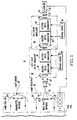
- This gas analyzer arrangement 10 includes a light source 12 which is effective for generating the electromagnetic radiation that is to be directed toward the area suspected of containing the gas of interest.
- the light source 12 includes a quartz halogen spotlight having associated therewith, a parabolic reflector 12a which in conjunction, serve to emit infrared radiation in a directed manner.
- other sources of electromagnetic radiation are contemplated as being within the scope of the present invention; for instance, depending on the spectra at which the gas of interest exhibits the optimum detectable absorption characteristics, it may be necessary to use an ultraviolet light source instead of an infrared one.
- the transmitted infrared from the light source 12 is directed toward the coal face or in fact, any other surface remote from the light source 12 between which the gas of interest can accumulate and for which the surface will provide the necessary back reflection of a portion of that electromagnetic radiation projected toward it.
- the back reflected electromagnetic radiation is picked up by a receiving arrangement 14 which is constructed in the form of a collection cassegrain. In this manner back reflected infrared radiation is reflected off of a parabolic surface 16 toward a focusing lens 18 and then through an opening 20.
- a collection cassegrain one skilled in the art would realize that the light receiving arrangement could be satisfied by the use of an alternate lens arrangement as for instance, a collecting telescope.
- the back reflected light from the receiving arrangement 14 falls on a light conditioning arrangement 22 which in this case can be provided by a collimating lens or the like.
- the collimating lens 22 is effective for directing the back reflected light hereinafter referred to as light signal 24, into a parallel stream of light which can be efficiently directed along the optical path formed by the components of the gas analyzer arrangement 10 of the present invention.
- light signal 24 will contain the necessary information from which the determination of the presence and/or quantity of the gas of interest as may occur in the path of the projected light source 12 may occur; that is, the light signal 24 will indicate whether and how much absorption has occurred in the specific spectra associated with the gas of interest.
- Light signal 24, after passing through the light con ditioning arrangement 22, is optically coupled to a fast light switch modulator illustrated in the dotted line block designated 30 in Figure 1.
- the fast light switch modulator 30 consists essentially of an input polarizer 32 which is effective for polarizing the light signal 24 in a specific direction, followed by a pair of electro optical modulating devices 34 and 36 which are constructed of a material having a high electro-optical coefficient, and then followed by a second polarizer 38 which is oriented in the same polarization direction as the input polarizer 32.
- the components of the fast light switch modulator 30 achieve a phenomenon known as the "Pockels" effect; such effect has the characteristic that, with the input polarizer 32 and the second polarizer 38 oriented in a parallel direction in the absence of an electric field applied to the electro-optical modulators 34, 36, all of the light signal 24 that passes through the input polarizer 32 also passes through the second polarizer 38. Subsequently, when an electric field is applied to the electro-optical modulators 34, 36, the linearly polarized light from the input polarizer 32 is rotated, wherein the degree of rotation increases with the magnitude of the applied electric field.
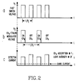
- the fast light switch modulator 30 is driven at a frequency of 100 kHz which thereby results in a 100 kHz signal which is proportional to the intensity of the light signal 24.
- the light signal 24, modulated to this first frequency of 100 kHz is illustrated in Figure 2A as a representative voltage v1.
- a first voltage source 28 which can be a conventional voltage source configured so as to provide the necessary voltage at the first frequency.
- the gas etalon modulator configuration 40 shown in Figure 1 essentially serves the purpose of determining the amounts of the received light signal 24 that has been removed by the absorption characteristics of the gas of interest.
- the gas etalon modulator 40 includes the second polarizer 38 which is shared with the fast light switch modulator 30 as well as a birefringent etalon device 42.
- the birefringent etalon device 42 has associated therewith, a free spectral range which matches the gas of interest in one transmitted polarization and correlates with the gas absorption spectra, but whose transmitted spectrum anti-correlates with the gas of interest in the orthogonal polarization.
- Etalon devices of the type used herein can be constructed of a suitable birefringent material such as a crystalline quartz; other examples of materials suitable for construction of etalon devices are: potassium dihydrogen phosphate (KDP), potassium di-Deuterium phosphate (KD*P), and ammonium dihydrogen phosphate (ADP). Additionally, the material lithium niobate can be used in an application of an etalon device where the direction of propagation of the light beam is transverse to the application of the electrical field used to modulate the birefringent etalon device.
- KDP potassium dihydrogen phosphate
- KD*P potassium di-Deuterium phosphate
- ADP ammonium dihydrogen phosphate
- the material lithium niobate can be used in an application of an etalon device where the direction of propagation of the light beam is transverse to the application of the electrical field used to modulate the birefringent etalon device.
- a second electro-optical modulator configuration 44, 46 Disposed next within the gas etalon modulator 40 adjacent the birefringent etalon device 42 is a second electro-optical modulator configuration 44, 46 which, similar to the electro-optical modulator 34, 36 of the fast light switch modulator 30, is constructed of a material having a high electro-optical coefficient. It should be understood that the second electro-optical modulator 44, 46 can be constructed of a pair of modulator elements or can in fact, perform the necessary modulation function when provided in the form of a single electro-optic modulator device.
- a second voltage source 48 is included as an element of the gas etalon modulator configuration 40 for the purpose of providing the necessary electric field to the second electro-optical modulator 44, 46.
- the second voltage source 48 provides a voltage v2 at a second frequency f2 which allows for the selection between the two periodic transmission spectra associated with the birefringent etalon device 42, these two spectra being the correlation and anti-correlation spectra.
- the relationship of the second voltage v2 and the second frequency f2 to the periodic spacing associated with the birefringent etalon 42 can best be seen with reference to the waveform of Figure 2B wherein it can be seen that the voltage v2 applied to the second electro-optical modulator 44, 46 is provided at a frequency f2 which is one half (1 ⁇ 2 ) the frequency f1 at which the voltage v1 is provided to the electro-optical modulator 34, 36 of the fast light switch modulator 30.
- Figure 2B further illustrates that for the anti-correlation spectra of the birefringent etalon 42, that is, the spectra at which the gas of interest exhibits no absorption properties, also occurs at one half (1 ⁇ 2 ) of the rate of the frequency f1.
- frequency f2 for purposes of discussion, it should be noted that for frequency f2 to be one half (1 ⁇ 2 ) of frequency f1 previously stated to be 100 kHz, frequency f2 must be set to 50 kHz. In this manner, the shifting between the correlation and anti-correlation spectra can occur at a fast enough rate to prevent errors from arising which may otherwise occur as a result of background movement during the cycle time of one absorption measurement.
- a third polarizer element 50 is also included as a part of the gas etalon modulator 40 and is oriented in a manner so as to pass only selected spectra.
- the light signal 24 passes through the gas etalon modulator 40 to a filter device 52 and lens element 54 configuration which are effective for removing unwanted wave portions of the light signal 24, prior to being input to the detector configuration 56.
- the detector configuration 56 determines the amount of the gas of interest present in the area under study by conventional means using the ratio of the absorptions between the correlation and anti-correlation spectra. Additionally, the detector configuration 56 performs the function of dividing the light signal at 50 kHz by the light signal 100 kHz which yields a signal that is proportional only to the gas concentration and is independent of the received light intensity value.
- the wave form shown in Figure 2C illustrates the independence between the gas concentration and the received light intensity factors in the form of a detector current measurement i d .
- the output of the detector device 56 can be coupled to a display arrangement 58 shown as an alphanumeric display segment and disposed within a hand held unit also containing the light source 12 and receiving arrangement 14.
- an alternate embodiment of the invention involves the substitution of the gas etalon modulator 40 shown in Figure 1 with one utilizing a compound Fabry-Perot etalon constructed in the manner illustrated in Figures 4A and 4B.
- a remote gas measuring arrangement which can be specifically applied to operate on a gas specie having associated therewith, a very precise narrow bandwidth absorption spectra.
- the technique of specifically tailoring a substantially identical registration of the absorption characteristics of certain gases, is commonly referred to as a high finesse or increased finesse technique.
- a filtering arrangement could be provided to substantially correlate with these lines, a more precise measurement essentially immune from interference would result. Accordingly, a gas analyzer arrangement which could provide for such precise correlation between the absorption spectra of the particular gas specie and the filtering capabilities of the interferometer arrangement should also provide a precise tailoring of the anti-correlation waveshape with which the absorption spectra is compared.
- the anti-correlation lines need not be constructed so as to fall directly between the correlation lines but in fact, because of the ability to precisely specify the location of these lines, they can be disposed near the correlation lines so as to avoid any absorption lines of another gas which may interfere with the accuracy of this desired measurement.
- Such a remote gas measuring arrangement can also be realized by the configuration illustrated in Figure 5 wherein a compound Fabry-Perot etalon 60 is used in conjunction with the electro-optical modulator 44, 46 to achieve the high finesse gas analyzer arrangement.
- the compound Fabry-Perot etalon 60 is further shown in Figure 46 wherein it is shown that the structure is such that the path length 1, in conjunction with the index of refraction n2, creates the exact registration of the gas specie of interest.
- the opposing surfaces formed along the longitudinal axis of the birefringent etalon 60 are coated with a partially reflective surface coating.
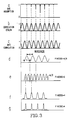
- the amount of reflectivity achieved by the surface coating is determinative of the sharpness of the absorption lines and hence, the high degree of finesse achieved as illustrated in Figure 3G. Accordingly, it can be appreciated that by varying the amount of surface coating reflectivity, the finesse can be increased or decreased to achieve the sharpness necessary for the anti-correlation waveform to avoid absorbing interference of another gas specie.
- the index of refraction n1 is determinative of the spacing of the anti-correlation waveshape and can be specified so as to achieve this spacing relative to the correlation waveshape as is necessary to avoid such interference from the absorption spectra of other gas species.
- the manner by which the selective spacing of the anti-correlation waveform can be achieved is best illustrated in Figure 4B wherein the optical axii of the compound Fabry-Perot interferometer 60 are illustrated.
- the index of refraction n2 which is determinative of the correlation waveform frequency spacing, is disposed along the (010) axis and, since this frequency spacing must correlate with the absorption spectra of the gas of interest, this index of refraction n2 must be set and not be variable.
- This selection effectively moves the anti-correlation lines shown in Figure 3G between the correlation lines to the optimum position to prevent interference and to thereafter set, for the remaining operating life cycle of the gas analyzer arrangement, those indices of refraction once the material structure has been cut.
- the gas analyzer arrangement 10 can be remotely operated as a hand held instrument whereby the instrument operator points the light source 12 in the area of concern such that the electromagnetic radiation is directed through a suspected quantity of the gas of interest and thereafter back reflected to the receiving arrangement 14 which can also be contained within the hand held portion of the gas analyzer arrangement 10.
- the back reflected light signal is picked up by the parabolic portion 16 of the receiving arrangement 14 and directed through the opening 20 by means of lens 18.
- the light signal from the receiving arrangement 14 then passes through the collimating lens 22 which directs the light beam in the parallel stream identified as light signal 24 and which has associated therewith, absorption spectra indicative of the presence of those gases, through which the electromagnetic radiation has passed.
- light signal 24 may contain absorbed spectra indicative of numerous gases, for the present purpose, this operation will be described with reference to a particular gas such as methane which has an absorption band near 3.4 micrometers in the infrared region. In the presence of methane the infrared radiation in this region will be reduced relative to the radiation in adjacent regions where no methane absorption exists, if the gas concentration in the measurement path would be sufficiently high.
- methane which has an absorption band near 3.4 micrometers in the infrared region.
- the parallel focused light signal 24 is then optically coupled to the fast light switch modulator 30.
- the input polarizer 32 of the fast light switch modulator 30 passes that portion of the light signal 24 which coincides with the direction of polarization which polarizer 32 is oriented.
- the polarized light signal 24 then passes through the electro-optical modulator configuration 34, 36 which configuration has applied thereto, a first voltage v1 modulated to a first frequency f1 and which in this instance, is set at 100 kHz.
- the applied electric field has the effect that, for each cycle associated with the electric field, the fast light switch modulator 30 acts as a filter such that one half of the filtered light signal 24 is blocked from exiting the fast light switch modulator 30.
- This filtering affect is achieved by the fact that the electric field shifts the polarization of the light signal 24 by 90° so that it cannot pass through the second polarizer 38 which is oriented in a parallel direction to that of the input polarizer 32.
- the light signal 24 at the first frequency f1 is optically coupled to the gas etalon modulator configuration 40 by means of the sharing arrangement of the second polarizer 38 with the fast light switch modulator 30.
- Light signal 24 is then passed to the birefringent etalon device 42 which has been sized specifically to correlate to the known absorption spectra of the gas of interest.
- the birefringent etalon device 42 For purposes of discussing the operation of the birefringent etalon device 42, reference will be made to the waveforms of Figures 3A through C.
- Figure 3A il lustrates the absorption spectra of the gas of interest
- Figure 3B illustrates the correlation waveform associated with the birefringent etalon device 42
- Figure 3C illustrates the anti-correlation waveform associated with the etalon device 42.
- the light signal 24 passing through the birefringent etalon device 42 during the correlation phase all of the radiation that passes through the etalon device 42 is capable of being strongly absorbed by the gas of interest.
- the anti-correlation condition which occurs when the electric field is applied to the electro-optic modulator arrangement 44, 46, the light signal 24 has none of its radiation absorbed by the gas of interest.
- the presence of the gas therefore produces a very strong change in the relative intensities of the signals reaching the detector 56 during correlation and anti-correlation.
- the wavelength shift employed between the correlation and anti-correlation conditions can be as little as a 1/10 of a wave number or less, so that the same spectral range is observed for both parts of the differential measurement. Only a substance exhibiting the sharp spectral absorption lines and regular periodic spacing of the gas to be measured will produce such an absorption signal.
- the light signal 24 which has been previously modulated to a 100 kHz frequency by the fast light switch modulator configuration 30, is also modulated by the gas etalon modulator configuration 40 to a frequency of 50 kHz which is utilized by the gas etalon modulator arrangement 40 for purposes of shifting between the correlation and anti-correlation conditions.
- the effect of such double modulation scheme is that the gas etalon modulator configuration 40 will be in the anti-correlation condition for every other occurrence of the application of the voltage v1 to the light signal 24.
- the light signal 24, following shifting between the correlation and anti-correlation conditions, is directed through the third polarizer 48 and then through the filter 52 and lens configuration 54 where the light signal 24 is stripped of unwanted wave portions prior to being input to the detector arrangement 56.
- the detector arrangement 56 before determining the concentration of the gas of interest that may be present in the area under test, must first distinguish between that portion of the received input light signal 24 which is representative of the intensity of the back reflected electromagnetic radiation and the portion of such light signal 24 as is representative of such gas concentration. For this purpose, the detector arrangement 56 divides the light signal 24 at the 50 kHz frequency by the light signal at the 100 kHz frequency which results in the generation of a signal representative only of the gas concentration; the portion of the light signal 24 representative of the intensity being effectively removed from consideration thereby.
- the detector arrangement 56 utilizes conventional means to determine the presence and/or quantity of the gas of interest by the ratio of the intensity of the absorption lines at the transmission spectra maxima and the point selected between the transmission spectra maxima for the anti-correlation waveform. IDENTIFICATION OF REFERENCE NUMERALS USED IN THE DRAWINGS LEGEND REF. NO.
- FIGURE VOLTAGE SOURCE 1 28 1 ELECTRO-OPTIC MODULATOR 34 1 ELECTRO-OPTIC MODULATOR 36 1 ELECTRO-OPTIC MODULATOR 44 1 ELECTRO-OPTIC MODULATOR 44 5 FLECTRO-OPTIC MODULATOR 46 1 ELECTRO-OPTIC MODULATOR 46 5 VOLTAGE SOURCE 2 48 1 VOLTAGE SOURCE 2 48 5 DETECTOR 56 1 COMPOUND F-P ETALON 60 5
Landscapes
- Physics & Mathematics (AREA)
- Spectroscopy & Molecular Physics (AREA)
- General Physics & Mathematics (AREA)
- Health & Medical Sciences (AREA)
- Life Sciences & Earth Sciences (AREA)
- Chemical & Material Sciences (AREA)
- Analytical Chemistry (AREA)
- Biochemistry (AREA)
- General Health & Medical Sciences (AREA)
- Immunology (AREA)
- Pathology (AREA)
- Investigating Or Analysing Materials By Optical Means (AREA)
- Sampling And Sample Adjustment (AREA)
- Other Investigation Or Analysis Of Materials By Electrical Means (AREA)
Applications Claiming Priority (2)
| Application Number | Priority Date | Filing Date | Title |
|---|---|---|---|
| US345858 | 1982-02-04 | ||
| US07/345,858 US5076699A (en) | 1989-05-01 | 1989-05-01 | Method and apparatus for remotely and portably measuring a gas of interest |
Publications (3)
| Publication Number | Publication Date |
|---|---|
| EP0396320A2 true EP0396320A2 (fr) | 1990-11-07 |
| EP0396320A3 EP0396320A3 (fr) | 1991-05-08 |
| EP0396320B1 EP0396320B1 (fr) | 1995-03-22 |
Family
ID=23356794
Family Applications (1)
| Application Number | Title | Priority Date | Filing Date |
|---|---|---|---|
| EP90304491A Expired - Lifetime EP0396320B1 (fr) | 1989-05-01 | 1990-04-26 | Méthode et appareil pour mesurer de loin un gaz |
Country Status (7)
| Country | Link |
|---|---|
| US (1) | US5076699A (fr) |
| EP (1) | EP0396320B1 (fr) |
| JP (1) | JPH0363547A (fr) |
| AT (1) | ATE120275T1 (fr) |
| CA (1) | CA2014876C (fr) |
| DE (1) | DE69017942T2 (fr) |
| NO (1) | NO901793L (fr) |
Cited By (4)
| Publication number | Priority date | Publication date | Assignee | Title |
|---|---|---|---|---|
| EP0467581A2 (fr) * | 1990-07-18 | 1992-01-22 | Secretary of State for Trade and Industry in Her Britannic Majesty's Gov. of the U.K. of Great Britain and Northern Ireland | Appareil optique de contrôle des gaz à chemin optique long |
| WO1993001477A1 (fr) * | 1991-07-12 | 1993-01-21 | The Secretary Of State For Defence In Her Britannic Majesty's Government Of The United Kingdom Of Great Britain And Northern Ireland | Traitement de signaux optiques |
| WO1996029591A1 (fr) * | 1995-03-21 | 1996-09-26 | Sci-Tec Instruments Inc. | Analyseur de gaz optique a correlation |
| EP1037025A2 (fr) * | 1999-03-05 | 2000-09-20 | Heraeus Noblelight GmbH | Sonde spectroscopique portable et miniaturisée |
Families Citing this family (32)
| Publication number | Priority date | Publication date | Assignee | Title |
|---|---|---|---|---|
| US5401967A (en) * | 1990-12-26 | 1995-03-28 | Colorado Seminary Dba University Of Denver | Apparatus for remote analysis of vehicle emissions |
| US5210702A (en) * | 1990-12-26 | 1993-05-11 | Colorado Seminary | Apparatus for remote analysis of vehicle emissions |
| US5245408A (en) * | 1991-01-11 | 1993-09-14 | The United States Of America As Represented By The Director, National Security Agency | Electro-optic coherent light detector |
| US5323229A (en) * | 1992-08-31 | 1994-06-21 | Science Applications International Corporation | Measurement system using optical coherence shifting interferometry |
| US5451787A (en) * | 1993-05-04 | 1995-09-19 | Westinghouse Electric Corporation | Hazardous air pollutants monitor |
| DE4320038C1 (de) * | 1993-06-17 | 1994-12-15 | Fraunhofer Ges Forschung | Anordnung zum Bewerten eines Meßsignals nach Betrag und Phase in Bezug auf ein Referenzsignal |
| US5440388A (en) * | 1993-08-02 | 1995-08-08 | Erickson; Jon W. | Chemical analysis and imaging by discrete fourier transform spectroscopy |
| US5438406A (en) * | 1993-10-07 | 1995-08-01 | The Titan Corporation | Tunable narrowband spectrometer with acousto-optical tunable filter |
| US5444528A (en) * | 1994-07-27 | 1995-08-22 | The Titan Corporation | Tunable spectrometer with acousto-optical tunable filter |
| US5698853A (en) * | 1995-04-18 | 1997-12-16 | Nikon Corporation | Infrared image pickup apparatus |
| US5909303A (en) * | 1996-01-04 | 1999-06-01 | The Board Of Trustees Of The Leland Stanford Junior University | Optical modulator and optical modulator array |
| US5946095A (en) * | 1996-03-08 | 1999-08-31 | Gas Research Institute | Natural gas detection apparatus and method operable in a moving vehicle |
| GB2314617B (en) * | 1996-06-24 | 2000-08-23 | Graviner Ltd Kidde | High sensitivity gas detection |
| US5831267A (en) * | 1997-02-24 | 1998-11-03 | Envirotest Systems Corp. | Method and apparatus for remote measurement of exhaust gas |
| US6008928A (en) * | 1997-12-08 | 1999-12-28 | The United States As Represented By The Administrator Of The National Aeronautics And Space Administration | Multi-gas sensor |
| US6574031B1 (en) | 1997-12-08 | 2003-06-03 | The United States Of America As Represented By The Administrator Of The National Aeronautics And Space Administration | Method for balancing detector output to a desired level of balance at a frequency |
| US6057923A (en) * | 1998-04-20 | 2000-05-02 | The United States Of America As Represented By The Administrator Of The National Aeronautics And Space Administration | Optical path switching based differential absorption radiometry for substance detection |
| EP1234164A1 (fr) | 1999-12-02 | 2002-08-28 | Ecolotrol, Inc. | Filtre |
| US6781110B2 (en) * | 2000-12-29 | 2004-08-24 | Spx Corporation | Apparatus and method for measuring vehicle speed and/or acceleration |
| US6561027B2 (en) | 2000-12-29 | 2003-05-13 | Spx Corporation | Support structure for system for measuring vehicle speed and/or acceleration |
| US6750444B2 (en) | 2000-12-29 | 2004-06-15 | Spx Corporation | Apparatus and method for measuring vehicle speed and/or acceleration |
| US6734422B2 (en) | 2001-03-21 | 2004-05-11 | Euv Llc | Portable outgas detection apparatus |
| US6576905B2 (en) | 2001-06-14 | 2003-06-10 | Gas Research Institute | Method and assembly for gas detection via a convergent birefringent filter |
| US6745613B2 (en) | 2001-08-13 | 2004-06-08 | Spx Corporation | Method and system for determining the type of fuel used to power a vehicle |
| US6857262B2 (en) | 2001-08-16 | 2005-02-22 | Spx Corporation | Catalytic converter function detection |
| US7183945B2 (en) * | 2001-08-17 | 2007-02-27 | Spx Corporation | Method and system for video capture of vehicle information |
| US20030034889A1 (en) | 2001-08-20 | 2003-02-20 | Rendahl Craig S. | Host system and method for sensed vehicle data |
| US6744516B2 (en) | 2001-08-21 | 2004-06-01 | Spx Corporation | Optical path structure for open path emissions sensing |
| US6757607B2 (en) | 2001-08-23 | 2004-06-29 | Spx Corporation | Audit vehicle and audit method for remote emissions sensing |
| US8599381B2 (en) | 2011-01-19 | 2013-12-03 | Massachusetts Institute Of Technology | Gas detector for atmospheric species detection |
| US10724945B2 (en) * | 2016-04-19 | 2020-07-28 | Cascade Technologies Holdings Limited | Laser detection system and method |
| GB201700905D0 (en) | 2017-01-19 | 2017-03-08 | Cascade Tech Holdings Ltd | Close-Coupled Analyser |
Citations (6)
| Publication number | Priority date | Publication date | Assignee | Title |
|---|---|---|---|---|
| US3171027A (en) * | 1961-06-26 | 1965-02-23 | Wallack Stanley | Infrared atmospheric contamination detector system with the detector interrupted at a sub-harmonic frequency of the source |
| US3370503A (en) * | 1963-12-09 | 1968-02-27 | Beckman Instruments Inc | Radiation comparison system |
| FR2274914A1 (fr) * | 1974-06-11 | 1976-01-09 | Allied Chem | Procede et appareil de detection d'une espece moleculaire dans un echantillon gazeux |
| US4204771A (en) * | 1978-05-08 | 1980-05-27 | Arthur Shull | Tuning of etalons |
| GB2174198A (en) * | 1985-04-25 | 1986-10-29 | Elf France | Interferometric device for detecting gas |
| EP0203767A2 (fr) * | 1985-05-20 | 1986-12-03 | Rosemount Analytical Inc. | Dispositif d'analyse par infrarouge utilisant un monochromateur acousto-optique, notamment pour la surveillance de l'émission de fumées |
Family Cites Families (6)
| Publication number | Priority date | Publication date | Assignee | Title |
|---|---|---|---|---|
| US4035643A (en) * | 1974-06-11 | 1977-07-12 | Allied Chemical Corporation | Infrared gas analysis |
| US4221472A (en) * | 1978-08-28 | 1980-09-09 | Bell Telephone Laboratories, Incorporated | Nonlinear optical apparatus using fabry-perot resonators |
| US4496839A (en) * | 1982-11-03 | 1985-01-29 | Spectral Sciences Incorporated | System and method for remote detection and identification of chemical species by laser initiated nonresonant infrared spectroscopy |
| US4594511A (en) * | 1985-03-29 | 1986-06-10 | Sri International | Method and apparatus for double modulation spectroscopy |
| GB8621438D0 (en) * | 1986-09-05 | 1986-10-15 | Secr Defence | Electro-optic device |
| US4905169A (en) * | 1988-06-02 | 1990-02-27 | The United States Of America As Represented By The United States Department Of Energy | Method and apparatus for simultaneously measuring a plurality of spectral wavelengths present in electromagnetic radiation |
-
1989
- 1989-05-01 US US07/345,858 patent/US5076699A/en not_active Expired - Fee Related
-
1990
- 1990-04-19 CA CA002014876A patent/CA2014876C/fr not_active Expired - Fee Related
- 1990-04-24 NO NO90901793A patent/NO901793L/no unknown
- 1990-04-26 DE DE69017942T patent/DE69017942T2/de not_active Expired - Fee Related
- 1990-04-26 AT AT90304491T patent/ATE120275T1/de active
- 1990-04-26 EP EP90304491A patent/EP0396320B1/fr not_active Expired - Lifetime
- 1990-05-01 JP JP2115671A patent/JPH0363547A/ja active Pending
Patent Citations (6)
| Publication number | Priority date | Publication date | Assignee | Title |
|---|---|---|---|---|
| US3171027A (en) * | 1961-06-26 | 1965-02-23 | Wallack Stanley | Infrared atmospheric contamination detector system with the detector interrupted at a sub-harmonic frequency of the source |
| US3370503A (en) * | 1963-12-09 | 1968-02-27 | Beckman Instruments Inc | Radiation comparison system |
| FR2274914A1 (fr) * | 1974-06-11 | 1976-01-09 | Allied Chem | Procede et appareil de detection d'une espece moleculaire dans un echantillon gazeux |
| US4204771A (en) * | 1978-05-08 | 1980-05-27 | Arthur Shull | Tuning of etalons |
| GB2174198A (en) * | 1985-04-25 | 1986-10-29 | Elf France | Interferometric device for detecting gas |
| EP0203767A2 (fr) * | 1985-05-20 | 1986-12-03 | Rosemount Analytical Inc. | Dispositif d'analyse par infrarouge utilisant un monochromateur acousto-optique, notamment pour la surveillance de l'émission de fumées |
Non-Patent Citations (1)
| Title |
|---|
| MACHINE DESIGN. vol. 54, no. 24, October 1982, CLEVELAND US page 48 "Portable radiometer identifies minerals in the field" * |
Cited By (10)
| Publication number | Priority date | Publication date | Assignee | Title |
|---|---|---|---|---|
| EP0467581A2 (fr) * | 1990-07-18 | 1992-01-22 | Secretary of State for Trade and Industry in Her Britannic Majesty's Gov. of the U.K. of Great Britain and Northern Ireland | Appareil optique de contrôle des gaz à chemin optique long |
| EP0467581A3 (en) * | 1990-07-18 | 1992-04-22 | The Secretary Of State For Trade And Industry In Her Britannic Majesty's Government Of The United Kingdom Of Great Britain And | Optical long-path gas monitoring apparatus |
| GB2247525B (en) * | 1990-07-18 | 1994-08-17 | Secretary Trade Ind Brit | Optical long-path gas monitoring apparatus |
| WO1993001477A1 (fr) * | 1991-07-12 | 1993-01-21 | The Secretary Of State For Defence In Her Britannic Majesty's Government Of The United Kingdom Of Great Britain And Northern Ireland | Traitement de signaux optiques |
| GB2272765A (en) * | 1991-07-12 | 1994-05-25 | Secr Defence | Optical signal processing |
| GB2272765B (en) * | 1991-07-12 | 1995-04-05 | Secr Defence | Optical signal processing |
| WO1996029591A1 (fr) * | 1995-03-21 | 1996-09-26 | Sci-Tec Instruments Inc. | Analyseur de gaz optique a correlation |
| US5696586A (en) * | 1995-03-21 | 1997-12-09 | Sci-Tec Instruments Inc. | Optical correlation gas analyzer |
| EP1037025A2 (fr) * | 1999-03-05 | 2000-09-20 | Heraeus Noblelight GmbH | Sonde spectroscopique portable et miniaturisée |
| EP1037025A3 (fr) * | 1999-03-05 | 2001-03-07 | Heraeus Noblelight GmbH | Sonde spectroscopique portable et miniaturisée |
Also Published As
| Publication number | Publication date |
|---|---|
| EP0396320A3 (fr) | 1991-05-08 |
| ATE120275T1 (de) | 1995-04-15 |
| NO901793L (no) | 1990-11-02 |
| NO901793D0 (no) | 1990-04-24 |
| EP0396320B1 (fr) | 1995-03-22 |
| CA2014876C (fr) | 2001-02-20 |
| DE69017942T2 (de) | 1995-12-21 |
| US5076699A (en) | 1991-12-31 |
| JPH0363547A (ja) | 1991-03-19 |
| CA2014876A1 (fr) | 1990-11-01 |
| DE69017942D1 (de) | 1995-04-27 |
Similar Documents
| Publication | Publication Date | Title |
|---|---|---|
| EP0396320B1 (fr) | Méthode et appareil pour mesurer de loin un gaz | |
| USRE35355E (en) | Method and arrangement for measuring the optical absorptions of gaseous mixtures | |
| CA1187716A (fr) | Systeme automatique acoustico-optique analyseur d'infrarouges | |
| US5255075A (en) | Optical sensor | |
| US5339155A (en) | Optical wavelength modulated long-path gas monitoring apparatus | |
| US4822169A (en) | Measuring assembly for analyzing electromagnetic radiation | |
| JPH06213813A (ja) | 物質および/またはその特性決定の方法と装置 | |
| WO2015038561A1 (fr) | Système de spectroscopie à peigne de fréquence activé par cavité utilisant une cavité à prisme | |
| JPS6049847B2 (ja) | 光の強度を測定する方法及び分光計 | |
| JPH0231820B2 (fr) | ||
| EP3811056B1 (fr) | Appareil et procede pour determiner la presence d'un gaz dans un volume de detection de gaz | |
| KR100340457B1 (ko) | 원형이색성,광학회전및흡수스펙트럼측정방법및이색계 | |
| US6992777B2 (en) | Birefringent Mach-Zehnder interferometer | |
| JPH0357942A (ja) | 干渉計形検出装置 | |
| JP3285365B2 (ja) | フォトアレイ検出器を備える回帰較正による回転補正器型分光エリプソメータシステム | |
| JPH04364442A (ja) | 炭素同位体分析装置 | |
| US5696586A (en) | Optical correlation gas analyzer | |
| US4383181A (en) | Method and apparatus for analyzing a gaseous mixture | |
| JPH0275936A (ja) | 小さなガス分子用の光学干渉法によるガス成分の測定装置 | |
| WO1994016311A1 (fr) | Analyseur de gaz | |
| US3549260A (en) | Spatially dispersive correlation interferometer | |
| US7030990B2 (en) | Controlled interference spectrometer | |
| US7515262B2 (en) | Crystal grating apparatus | |
| CN108760653A (zh) | 一种光谱仪精确测量二氧化硫气体浓度的方法 | |
| CN108548787A (zh) | 一种光谱仪精确测量硫化氢气体浓度的方法 |
Legal Events
| Date | Code | Title | Description |
|---|---|---|---|
| PUAI | Public reference made under article 153(3) epc to a published international application that has entered the european phase |
Free format text: ORIGINAL CODE: 0009012 |
|
| AK | Designated contracting states |
Kind code of ref document: A2 Designated state(s): AT BE CH DE FR GB IT LI LU NL SE |
|
| PUAL | Search report despatched |
Free format text: ORIGINAL CODE: 0009013 |
|
| AK | Designated contracting states |
Kind code of ref document: A3 Designated state(s): AT BE CH DE FR GB IT LI LU NL SE |
|
| 17P | Request for examination filed |
Effective date: 19911104 |
|
| 17Q | First examination report despatched |
Effective date: 19930505 |
|
| GRAA | (expected) grant |
Free format text: ORIGINAL CODE: 0009210 |
|
| AK | Designated contracting states |
Kind code of ref document: B1 Designated state(s): AT BE CH DE FR GB IT LI LU NL SE |
|
| PG25 | Lapsed in a contracting state [announced via postgrant information from national office to epo] |
Ref country code: LI Effective date: 19950322 Ref country code: CH Effective date: 19950322 Ref country code: BE Effective date: 19950322 Ref country code: AT Effective date: 19950322 |
|
| REF | Corresponds to: |
Ref document number: 120275 Country of ref document: AT Date of ref document: 19950415 Kind code of ref document: T |
|
| REF | Corresponds to: |
Ref document number: 69017942 Country of ref document: DE Date of ref document: 19950427 |
|
| PG25 | Lapsed in a contracting state [announced via postgrant information from national office to epo] |
Ref country code: LU Free format text: LAPSE BECAUSE OF NON-PAYMENT OF DUE FEES Effective date: 19950430 |
|
| ITF | It: translation for a ep patent filed |
Owner name: BARZANO'E ZANARDO S.P.A. |
|
| PG25 | Lapsed in a contracting state [announced via postgrant information from national office to epo] |
Ref country code: SE Effective date: 19950622 |
|
| REG | Reference to a national code |
Ref country code: CH Ref legal event code: PL |
|
| ET | Fr: translation filed | ||
| PLBE | No opposition filed within time limit |
Free format text: ORIGINAL CODE: 0009261 |
|
| STAA | Information on the status of an ep patent application or granted ep patent |
Free format text: STATUS: NO OPPOSITION FILED WITHIN TIME LIMIT |
|
| 26N | No opposition filed | ||
| PGFP | Annual fee paid to national office [announced via postgrant information from national office to epo] |
Ref country code: NL Payment date: 20011031 Year of fee payment: 13 |
|
| REG | Reference to a national code |
Ref country code: GB Ref legal event code: IF02 |
|
| PG25 | Lapsed in a contracting state [announced via postgrant information from national office to epo] |
Ref country code: NL Free format text: LAPSE BECAUSE OF NON-PAYMENT OF DUE FEES Effective date: 20031101 |
|
| NLV4 | Nl: lapsed or anulled due to non-payment of the annual fee |
Effective date: 20031101 |
|
| PGFP | Annual fee paid to national office [announced via postgrant information from national office to epo] |
Ref country code: FR Payment date: 20040503 Year of fee payment: 15 |
|
| PGFP | Annual fee paid to national office [announced via postgrant information from national office to epo] |
Ref country code: GB Payment date: 20040505 Year of fee payment: 15 |
|
| PGFP | Annual fee paid to national office [announced via postgrant information from national office to epo] |
Ref country code: DE Payment date: 20040601 Year of fee payment: 15 |
|
| PG25 | Lapsed in a contracting state [announced via postgrant information from national office to epo] |
Ref country code: IT Free format text: LAPSE BECAUSE OF NON-PAYMENT OF DUE FEES;WARNING: LAPSES OF ITALIAN PATENTS WITH EFFECTIVE DATE BEFORE 2007 MAY HAVE OCCURRED AT ANY TIME BEFORE 2007. THE CORRECT EFFECTIVE DATE MAY BE DIFFERENT FROM THE ONE RECORDED. Effective date: 20050426 Ref country code: GB Free format text: LAPSE BECAUSE OF NON-PAYMENT OF DUE FEES Effective date: 20050426 |
|
| PG25 | Lapsed in a contracting state [announced via postgrant information from national office to epo] |
Ref country code: DE Free format text: LAPSE BECAUSE OF NON-PAYMENT OF DUE FEES Effective date: 20051101 |
|
| GBPC | Gb: european patent ceased through non-payment of renewal fee |
Effective date: 20050426 |
|
| PG25 | Lapsed in a contracting state [announced via postgrant information from national office to epo] |
Ref country code: FR Free format text: LAPSE BECAUSE OF NON-PAYMENT OF DUE FEES Effective date: 20051230 |
|
| REG | Reference to a national code |
Ref country code: FR Ref legal event code: ST Effective date: 20051230 |