EP0392177B1 - Stabilized vehicle articulation system - Google Patents
Stabilized vehicle articulation system Download PDFInfo
- Publication number
- EP0392177B1 EP0392177B1 EP90103823A EP90103823A EP0392177B1 EP 0392177 B1 EP0392177 B1 EP 0392177B1 EP 90103823 A EP90103823 A EP 90103823A EP 90103823 A EP90103823 A EP 90103823A EP 0392177 B1 EP0392177 B1 EP 0392177B1
- Authority
- EP
- European Patent Office
- Prior art keywords
- articulated
- hydraulic cylinder
- damping device
- damper
- carriage
- Prior art date
- Legal status (The legal status is an assumption and is not a legal conclusion. Google has not performed a legal analysis and makes no representation as to the accuracy of the status listed.)
- Expired - Lifetime
Links
Images


Classifications
-
- B—PERFORMING OPERATIONS; TRANSPORTING
- B62—LAND VEHICLES FOR TRAVELLING OTHERWISE THAN ON RAILS
- B62D—MOTOR VEHICLES; TRAILERS
- B62D47/00—Motor vehicles or trailers predominantly for carrying passengers
- B62D47/02—Motor vehicles or trailers predominantly for carrying passengers for large numbers of passengers, e.g. omnibus
- B62D47/025—Motor vehicles or trailers predominantly for carrying passengers for large numbers of passengers, e.g. omnibus articulated buses with interconnecting passageway, e.g. bellows
-
- B—PERFORMING OPERATIONS; TRANSPORTING
- B62—LAND VEHICLES FOR TRAVELLING OTHERWISE THAN ON RAILS
- B62D—MOTOR VEHICLES; TRAILERS
- B62D53/00—Tractor-trailer combinations; Road trains
- B62D53/04—Tractor-trailer combinations; Road trains comprising a vehicle carrying an essential part of the other vehicle's load by having supporting means for the front or rear part of the other vehicle
- B62D53/08—Fifth wheel traction couplings
- B62D53/0871—Fifth wheel traction couplings with stabilising means, e.g. to prevent jack-knifing, pitching, rolling, buck jumping
- B62D53/0878—Fifth wheel traction couplings with stabilising means, e.g. to prevent jack-knifing, pitching, rolling, buck jumping the fifth wheel coupling incorporating braking or restraining means
Definitions
- the invention relates to a joint damping device for use in an articulated bus with a front end and a follower connected to it via a swivel head (swivel joint), at least one hydraulic cylinder or shock absorber being arranged between the two end components.
- Articulation angle controls for articulated buses in the form of articulation angle locks or articulation angle dampers are known in the most varied versions. Only the three systems essentially used in practice will be discussed here.
- One version (DE-OS 24 20 203) of the articulation angle lock with two hydraulic cylinders arranged between the front end and the trailer is known, the actuation for blocking the articulation is carried out via two potentiometers, electronics and a hydraulic control block, and the articulation angle is blocked from the comparison of the steering angle / Buckling angle results, whereby the parameters driving speed, buckling angle speed and buckling angle acceleration may also be included.
- DE-OS 36 23 655 Another embodiment variant (DE-OS 36 23 655) has a double-acting hydraulic cylinder attached to the front of the vehicle and lying transversely to the direction of travel longitudinally displaceable cylinder jacket two steel cables are attached, which, guided by a turntable, are attached to the slewing ring part of the trailer.
- the control is carried out via two potentiometers, an electronics and a hydraulic control block. You can also switch to constant damping manually.
- the object of the invention is to provide a simple device for regulating the buckling stability as a function of the damping torque via the buckling angle to create a complex electronic-hydraulic control and function monitoring.
- a hydraulic cylinder or a shock absorber is arranged between the front carriage and the follower connected to the outer ring of the slewing ring or between the follower and the front carriage connected to the slewing ring inner ring in the longitudinal median plane of the articulated bus, which is in the extended position of the articulated bus in its interior Dead center position and a further hydraulic cylinder or shock absorber is arranged in parallel to the hydraulic cylinder or the shock absorber, which is preferably in a slightly inclined position at a distance from the longitudinal center plane of the articulated bus in the middle stroke position when the articulated bus is extended, the hydraulic cylinder or the shock absorber being one End is pivotally attached to the respective carriage component and other end in the transverse central plane of the respective slewing ring part.
- the stroke and thus also the damping torque of the hydraulic cylinder or shock absorber depends on the articulation angle between the front end and the rear end, with the tendency that the moment 0 is present when driving straight ahead, with minor deviations
- the damping moments increase exponentially according to an initially degressive, then transitioning into a progressive curve, so that the requirements of practice, namely the risk of folding knife-like kinking with increasing kink angle the wagon components are optimally counteracted using the simplest means.
- the moment curve when pressure is exerted on the cylinder piston or damper piston is much flatter than when pulling, ie there is more resistance to entering the curve than to extending (extension of the articulated cable).
- the inventive articulated joint protection basically works with one hydraulic cylinder or shock absorber each. It is the cheapest solution. However, two hydraulic cylinders or two shock absorbers with different purposes can also be used according to claim 2, namely in order to be able to work with slimmer cylinders for space reasons or to create a redundant system in the case of cylinder diameters that are not reduced, which also impair the function of the driving operation in the event of damage excludes.
- an adjustable throttle valve is arranged in the connecting line between the connections of the displacement spaces of the hydraulic cylinder.
- the damping torque can be modified and, if necessary, adapted to the geographical and seasonal route conditions.
- An adjustable throttle valve can also be assigned to each connection in the connecting line between the connections of the hydraulic cylinder, the other connection being blocked via check valves.
- a plurality of throttle valves of different throttle cross-section connected in parallel are arranged in a line, the different throttle valves being switchable to different kink angle ranges. In this way, particularly vulnerable buckling angle ranges can be more clearly delimited.
- constant damping results, which can be set as high as desired and which results from the assignment of a pressure relief valve.
- This higher constant damping may prove necessary, e.g. when exiting parking bays or suddenly occurring dangerous road conditions, e.g. on icy roads.
- the constant damping can be switched on both from the driver's subjective feeling at the push of a button and objectively controlled by an ABS / ASR system.
- shock absorbers with different damper characteristics over the stroke can also be used, wherein one or more grooves are arranged in the cylinder wall in the middle stroke area in order to achieve a lower damping, so that the area around the extended position of the articulated train permits faster maneuvering movements.
- FIGS. 5 and 6. 1 to 4 and their accompanying diagrams serve to understand the invention by outlining the problem and the solution.
- a hydraulic cylinder 2 or shock absorber 2 ' is arranged in the longitudinal center plane of the vehicle between the front carriage 3 and the swivel ring outer ring 1' connected to the follower 6 via swivel joints 7.
- the hydraulic cylinder 2 ' is connected via swivel or ball joint 4 to the swivel ring outer ring 1' and via swivel or ball joint 5 is connected to the front end 3.
- the hydraulic cylinder 2 or shock absorber 3 assumes its inner dead position, ie the piston stroke, damping force and damping torque are equal to 0.
- a hydraulic cylinder 19 or shock absorber 19 ' is arranged between the front carriage 3 and the swivel ring outer ring 1' connected to the follower 6 via swivel joints 7 in such a way that it is pivotable at one end via a swivel or ball joint 5 on the front carriage 3 and the other end via a swivel or ball joint 4 is connected to the outer part 1 'of the slewing ring, attached below the slewing ring in the transverse central plane, wherein the cylinder 19 or the shock absorber 19 'is arranged at a distance, preferably in a slightly inclined position, to the longitudinal center plane of the vehicle and the hydraulic cylinder 19 or shock absorber 19' is in the middle lifting position when the vehicle is in the extended position.
- the piston stroke H and the piston speed V b are plotted over the articulation angle ⁇ , the cylinder or damper piston being in its middle stroke position when the articulation is in the extended position.
- V b ⁇ stroke ⁇ ⁇ ⁇ V ⁇
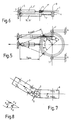
- FIGS. 1, 2 and 3 show the joint damping device according to the invention on an articulated bus, which represents a combination of the systems according to FIGS. 1, 2 and 3, 4.
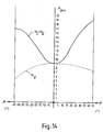
- a hydraulic cylinder 2 or shock absorber 2 'in its special arrangement is connected in parallel with a hydraulic cylinder 19 or shock absorber 19' in its special arrangement, so that a damping torque characteristic according to FIG. 14 is achieved, the damping torque already in the extended position of the Vehicle has a certain amount and later turns into a progressive curve that meets the higher damping requirements with increasing kink angle.
- the course of the stabilizing torque can be changed by changing the throttle cross sections or the articulation points of the hydraulic cylinder 19 or the shock absorber 19 'in such a way that the curve branches run symmetrically on both sides of the ordinate.
- the arrangement of the stabilizing joint according to FIGS. 5 and 6 with the associated course of the damping torque according to FIG. 14 shows the practical optimization of the system according to the invention, namely that a certain damping moment is built up in the extended position of the joint pull when buckling Counteracts "wagging" of the vehicle and, with a larger articulation angle, the damping torque increases progressively in relation to the risk of articulation.
- FIG. 15 shows a hydraulic circuit diagram with a cylinder 2, 19, which has connections 10 and 11 at its ends, which are connected by a line 9.
- adjustable throttle valves 12 and 13 are arranged on parallel connecting strands. In each case one line can be acted on, since shut-off valves 14, 15 are installed between the lines are, between which a line runs, in which a pressure relief valve 16 is installed.
- a pressure accumulator 18 is installed in the system to compensate for leakage losses and different stroke volumes. If a throttle valve, e.g. 12, is arranged, this can be used to modify the damping torque, while if two throttles 12 and 13 are arranged, they can both serve to modify the damping torque, but also have the task of designing the joint stabilization system according to FIGS.
- shut-off valve 17 a constant damping which is desirable in various situations can be switched on, the amount of which can be adjusted via the pressure relief valve 16.
- the shut-off valve 17 can be switched on by the driver by hand using a corresponding pushbutton in the dangerous situation or can be activated automatically by an ABS / ASR system.
Abstract
Description
Die Erfindung bezieht sich auf eine Gelenkdämpfungsvorrichtung zur Verwendung bei einem Gelenkomnibus mit einem Vorderwagen und einem mit diesem über einen Drehkranz (Drehgelenk) verbundenen Nachläufer, wobei zwischen den beiden Wagenkomponenten wenigstens ein Hydraulikzylinder oder Stoßdämpfer angeordnet ist.The invention relates to a joint damping device for use in an articulated bus with a front end and a follower connected to it via a swivel head (swivel joint), at least one hydraulic cylinder or shock absorber being arranged between the two end components.
Gelenkomnibusse mit Heckmotor und Antrieb auf der Nachläuferachse - sogenannte gedrückte oder geschobene Systeme - benötigen für den Wintereinsatz eine Knickschutzanlage. Darüber hinaus ist für solche Gelenkbuskonzeptionen wegen besonderer Massenverteilung, insbesondere aber bei höheren Fahrgeschwindigkeiten, aus Stabilitätsgründen eine Dämpfung im Gelenkbereich erforderlich.Articulated buses with a rear engine and drive on the trailing axle - so-called pushed or pushed systems - require an anti-kink system for winter use. In addition, damping in the joint area is required for such articulated bus designs because of special mass distribution, but in particular at higher driving speeds, for reasons of stability.
Knickwinkelsteuerungen für Gelenkomnibusse in der Form von Knickwinkelsperren oder Knickwinkeldämpfern sind in den manigfaltigsten Ausführungen bekannt. Es soll hier nur auf die drei im wesentlichen in praxi angewandten Systeme eingegangen werden. So ist eine Ausführung (DE-OS 24 20 203) der Knickwinkelsperre mit zwei zwischen Vorderwagen und Nachläufer angeordneten Hydraulikzylindern bekannt, deren Ansteuerung zum Blockieren des Knickgelenks über zwei Potentiometer, einer Elektronik und einem hydraulischen Steuerblock erfolgt und die Sperrung des Knickwinkels aus dem Vergleich Lenkwinkel/Knickwinkel resultiert, wobei u.U. auch noch die Parameter Fahrgeschwindigkeit, Knickwinkelgeschwindigkeit und Knickwinkelbeschleunigung mit einbezogen werden. Eine andere Ausführungsvariante (DE-OS 36 23 655) weist einen am Vorderwagen angebrachten, quer zur Fahrtrichtung liegenden, doppelt wirkenden Hydraulikzylinder auf, an dessen längsverschieblichem Zylindermantel zwei Stahlseile angebracht sind, die, über einen Drehschemel geführt, am Drehkranzteil des Nachläufers befestigt sind. Die Steuerung erfolgt knickwinkelgeschwindigkeitsabhängig über zwei Potentiometer, einer Elektronik und einem hydraulischen Steuerblock. Auch kann manuell auf Konstantdämpfung geschaltet werden.Articulation angle controls for articulated buses in the form of articulation angle locks or articulation angle dampers are known in the most varied versions. Only the three systems essentially used in practice will be discussed here. One version (DE-OS 24 20 203) of the articulation angle lock with two hydraulic cylinders arranged between the front end and the trailer is known, the actuation for blocking the articulation is carried out via two potentiometers, electronics and a hydraulic control block, and the articulation angle is blocked from the comparison of the steering angle / Buckling angle results, whereby the parameters driving speed, buckling angle speed and buckling angle acceleration may also be included. Another embodiment variant (DE-OS 36 23 655) has a double-acting hydraulic cylinder attached to the front of the vehicle and lying transversely to the direction of travel longitudinally displaceable cylinder jacket two steel cables are attached, which, guided by a turntable, are attached to the slewing ring part of the trailer. Depending on the buckling angle speed, the control is carried out via two potentiometers, an electronics and a hydraulic control block. You can also switch to constant damping manually.
Der für die bekannten Systeme notwendige hydraulische sowie elektronisch-elektrische Steuerungs- und Überwachungsaufwand ist erheblich. Abgesehen von der Störanfälligkeit in den umfangreich installierten elektrischen Anschlüssen und Bauteilen ist auch eine sehr zeitaufwendige und damit kostenintensive Einstell- und Abgleichprozedur erforderlich, die außerdem nur von geschultem Fachpersonal vorgenommen werden kann. Die Exporttauglichkeit eines solcherart ausgerüsteten Gelenkommibusses ist sehr eingeschränkt. Gefragt sind daher einfache, überschaubare Knickschutzsysteme, die bei Bedarf auch von durchschnittlich qualifiziertem Montagepersonal gewartet oder instandgesetzt werden können.The hydraulic and electronic-electrical control and monitoring effort required for the known systems is considerable. In addition to the susceptibility to faults in the extensively installed electrical connections and components, a very time-consuming and therefore costly setting and adjustment procedure is required, which can also only be carried out by trained specialist personnel. The suitability for export of such an articulated bus is very limited. What is needed are simple, manageable kink protection systems that can also be serviced or repaired by average qualified installation personnel if required.
Es ist eine Gelenkdämpfungsvorrichtung gemäß dem Oberbegriff des Anspruch 1 (DE 27 48 713 A1) bekannt, die ohne elektronische Steuerungselemente auskommt, wobei von der selbsttätigen Anpassung an die Straßenverhältnisse Gebrauch gemacht wird und die zwischen dem Primärwagen und Sekundärwagen angeordneten Zylinder als vorgespannte Dämpferzylinder ausgebildet sind, die stabilisierend auf das Kurvenverhalten des Gelenkzuges wirken.There is a joint damping device according to the preamble of claim 1 (DE 27 48 713 A1), which does not require electronic control elements, use being made of automatic adaptation to the road conditions and the cylinders arranged between the primary car and secondary car being designed as pre-tensioned damper cylinders , which have a stabilizing effect on the curve behavior of the joint pull.
Der Erfindung liegt die Aufgabe zugrunde, eine einfache Vorrichtung zur Regelung der Knickstabilität in Abhängigkeit vom Dämpfungsmoment über den Knickwinkel unter Verzicht auf eine aufwendige elektronisch-hydraulische Steuerung und Funktionsüberwachung zu schaffen.The object of the invention is to provide a simple device for regulating the buckling stability as a function of the damping torque via the buckling angle to create a complex electronic-hydraulic control and function monitoring.
Dies wird erfindungsgemäß dadurch erreicht, daß zwischen dem Vorderwagen und dem mit dem Drehkranzaußenring verbundene Nachläufer oder zwischen dem Nachläufer und dem mit dem Drehkranzinnenring verbundenen Vorderwagen in der Längsmittelebene des Gelenkomnibusses ein Hydraulikzylinder oder ein Stoßdämpfer angeordnet ist, der sich in Strecklage des Gelenkomnibusses in seiner inneren Totpunktlage befindet und in Parallelschaltung zu dem Hydraulikzylinder oder dem Stoßdämpfer ein weiterer Hydraulikzylinder oder Stoßdämpfer angeordnet ist, der sich, vorzugsweise in leichter Schräglage, mit Abstand zur Längsmittelebene des Gelenkomnibusses bei Strecklage des Gelenkomnibusses in seiner mittleren Hubstellung befindet, wobei der Hydraulikzylinder oder der Stoßdämpfer einen Endes an der jeweiligen Wagenkomponente und anderen Endes in der Quermittelebene des jeweiligen Drehkranzteils schwenkbar befestigt ist.This is achieved according to the invention in that a hydraulic cylinder or a shock absorber is arranged between the front carriage and the follower connected to the outer ring of the slewing ring or between the follower and the front carriage connected to the slewing ring inner ring in the longitudinal median plane of the articulated bus, which is in the extended position of the articulated bus in its interior Dead center position and a further hydraulic cylinder or shock absorber is arranged in parallel to the hydraulic cylinder or the shock absorber, which is preferably in a slightly inclined position at a distance from the longitudinal center plane of the articulated bus in the middle stroke position when the articulated bus is extended, the hydraulic cylinder or the shock absorber being one End is pivotally attached to the respective carriage component and other end in the transverse central plane of the respective slewing ring part.
Bei ausschließlicher Betrachtung des in der Längsmittelebene des Gelenkbusses angeordneten Hydraulikzylinders oder Stoßdämpfers ist der Hub und damit auch das Dämpfungsmoment des Hydraulikzylinders oder Stoßdämpfers abhängig vom Knickwinkel zwischen Vorderwagen und Nachläufer, und zwar mit der Tendenz, daß bei Geradeausfahrt das Moment 0 vorliegt, bei kleineren Abweichungen von der Geradeausfahrt kleine Dämpfungsmomente anliegen und mit zunehmendem Knickwinkel die Dämpfungsmomente gemäß einer zunächst degressiven, dann in eine progressive Kurve übergehend, exponentional anwachsen, so daß den Erfordernissen der Praxis, nämlich der mit zunehmendem Knickwinkel wachsenden Gefahr der klappmesserartigen Einknickung der Wagenkomponenten unter Anwendung einfachster Mittel optimal entgegengewirkt wird. Die Momentenkurve bei Druck auf den Zylinderkolben oder Dämpferkolben verläuft wesentlich flacher als bei Zug, d.h., dem Einfahren in die Kurve wird mehr Widerstand entgegengesetzt als dem Ausfahren (Streckung des Gelenkzuges).When only considering the hydraulic cylinder or shock absorber arranged in the longitudinal center plane of the articulated bus, the stroke and thus also the damping torque of the hydraulic cylinder or shock absorber depends on the articulation angle between the front end and the rear end, with the tendency that the
Bei ausschließlicher Betrachtung des mit Abstand zur Längsmittelebene angeordneten Hydraulikzylinders oder Stoßdämpfers ist auch bei Geradeausfahrt ein beträchtliches Moment vorhanden, so daß auch schon in der Strecklage eine das Schlingern verhindernde Dämpfung vorhanden ist. Durch die Kombination des in der Längsmittelebene und des im Abstand zu der Längsmittelebene angeordneten Zylinders in Parallelschaltung wird eine Charakteristik des Dämpfungsmomentes erzielt, die sich aus der Überlagerung der Dämpfungsmomente der einzelnen Zylinder ergibt, d.h., es steht schon bei der Strecklage ein Dämpfungsmoment zur Verfügung, das dann in einen progressiven Dämpfungsverlauf übergeht. Somit sind auch Situationen bei schwierigem Anfahren aus der Parkbucht, insbesondere aber eisglatten Straßenverhältnissen gut beherrschbar. Mittels der erfinderischen Anordnung wird auf wirtschaftlichste Art und Weise eine allen Straßen- und Fahrverhältnissen gerechtwerdende optimale Dämpfung erzielt.When looking exclusively at the hydraulic cylinder or shock absorber, which is arranged at a distance from the longitudinal center plane, there is a considerable moment even when driving straight ahead, so that even in the stretched position there is damping to prevent it from rolling. Through the combination of the cylinder arranged in parallel in the longitudinal center plane and the cylinder arranged at a distance from the longitudinal center plane, a characteristic of the damping moment is obtained which results from the superimposition of the damping moments of the individual cylinders, ie a damping moment is already available in the extended position, which then turns into a progressive damping curve. This means that even situations with difficult starting from the parking bay, but especially icy road conditions, can be mastered. By means of the arrangement according to the invention, an optimal damping which is suitable for all road and driving conditions is achieved in the most economical manner.
Der erfinderische Knickgelenkschutz funktioniert grundsätzlich mit je einem Hydraulikzylinder oder Stoßdämpfer. Das ist die billigste Lösung. Es können aber auch nach Anspruch 2 je zwei Hydraulikzylinder oder je zwei Stoßdämpfer mit unterschiedlicher Zweckstellung eingesetzt werden, nämlich um aus Raumgründen mit schlankeren Zylindern arbeiten zu können oder aber bei nicht reduzierten Zylinderdurchmessern ein redundantes System zu schaffen, das auch im Schadensfall eine Funktionsbeeinträchtigung des Fahrbetriebes ausschließt.The inventive articulated joint protection basically works with one hydraulic cylinder or shock absorber each. It is the cheapest solution. However, two hydraulic cylinders or two shock absorbers with different purposes can also be used according to
Nach einem Merkmal der Erfindung ist in der Verbindungsleitung zwischen den Anschlüssen der Verdrängungsräume des Hydraulikzylinders ein einstellbares Drosselventil angeordnet. Solcherart kann das Dämpfungsmoment modifiziert werden und gegebenenfalls den geographischen und jahreszeitlichen Streckenbedingungen angepaßt werden. Es kann auch in der Verbindungsleitung zwischen den Anschlüssen des Hydraulikzylinders jedem Anschluß je ein einstellbares Drosselventil zugeordnet sein, wobei der jeweils andere Anschluß über Rückschlagventile gesperrt ist.According to a feature of the invention, an adjustable throttle valve is arranged in the connecting line between the connections of the displacement spaces of the hydraulic cylinder. In this way, the damping torque can be modified and, if necessary, adapted to the geographical and seasonal route conditions. An adjustable throttle valve can also be assigned to each connection in the connecting line between the connections of the hydraulic cylinder, the other connection being blocked via check valves.
Nach einem anderen Merkmal der Erfindung ist vorgesehen, daß in einer Leitung mehrere parallelgeschaltete Drosselventile unterschiedlichen Drosselquerschnitts angeordnet sind, wobei die unterschiedlichen Drosselventile auf unterschiedliche Knickwinkelbereiche umschaltbar sind. Auf diese Weise können besonders gefährdete Knickwinkelbereiche deutlicher abgegrenzt werden.According to another feature of the invention, it is provided that a plurality of throttle valves of different throttle cross-section connected in parallel are arranged in a line, the different throttle valves being switchable to different kink angle ranges. In this way, particularly vulnerable buckling angle ranges can be more clearly delimited.
Indem ein Absperrventil in den hydraulischen Kreislauf eingesetzt wird, ergibt sich eine Konstantdämpfung, die beliebig hoch angesetzt sein kann und die sich durch die Zuordnung eines Überdruckventiles ergibt. Diese höhere Konstantdämpfung kann sich als notwendig erweisen, z.B. beim Ausfahren aus Parkbuchten oder bei plötzlich auftretenden gefährlichen Straßenverhältnissen, z.B. auf eisglatter Straße. Die Einschaltung der Konstantdämpfung kann sowohl aus dem subjektiven Empfinden des Fahrers über Tastendruck erfolgen als auch objektiv von einem ABS/ASR-System eingesteuert werden.By using a shut-off valve in the hydraulic circuit, constant damping results, which can be set as high as desired and which results from the assignment of a pressure relief valve. This higher constant damping may prove necessary, e.g. when exiting parking bays or suddenly occurring dangerous road conditions, e.g. on icy roads. The constant damping can be switched on both from the driver's subjective feeling at the push of a button and objectively controlled by an ABS / ASR system.
Gemäß einer alternativen Lösung zum Einsatz von Hydraulikzylindern können auch Stoßdämpfer mit über den Hubweg unterschiedlicher Dämpfercharakteristik zur Anwendung kommen, wobei im mittleren Hubbereich eine oder mehrere Nuten in der Zylinderwand zur Erzielung einer geringeren Dämpfung angeordnet sind, so daß der Bereich um die Strecklage des Gelenkzuges schnellere Manövrierbewegungen zuläßt.According to an alternative solution for the use of hydraulic cylinders, shock absorbers with different damper characteristics over the stroke can also be used, wherein one or more grooves are arranged in the cylinder wall in the middle stroke area in order to achieve a lower damping, so that the area around the extended position of the articulated train permits faster maneuvering movements.
Die Erfindung ist in einem Ausführungsbeispiel dargestellt und beschrieben.The invention is illustrated and described in an exemplary embodiment.
Es zeigen:
- Fig. 1
- eine Gelenkdämpfungsvorrichtung in der Draufsicht,
- Fig. 2
- eine Gelenkdämpfungsvorrichtung in Seitenansicht und Teilschnitt,
- Fig. 3
- eine Alternative eines Gelenkdämpfungsvorrichtung in der Draufsicht,
- Fig. 4
- eine Alternative eines Gelenkdämpfungsvorrichtung in Seitenansicht und Teilschnitt,
- Fig. 5
- die erfindungsgemäße Gelenkdämpfungsvorrichtung in der Draufsicht,
- Fig. 6
- die erfindungsgemäße Gelenkdämpfungsvorrichtung in Seitenansicht und Teilschnitt,
- Fig. 7
- eine schematische Darstellung eines Gelenkomnibusses
- Fig. 8
- ein Kräftedreieck zum Drehgelenk,
- Fig. 9
- ein Diagramm mit FQ über KW,
- Fig. 10
- ein Diagramm Zylinderhub und Kolbengeschwindigkeit über Knickwinkel (zu Fig. 1 und 2),
- Fig. 11
- ein Diagramm Stabilisierungsmoment um die Hochachse über dem Knickwinkel (zu Fig. 1 und 2),
- Fig. 12
- ein Diagramm Zylinderhub und Kolbengeschwindigkeit über dem Knickwinkel (zu Fig. 3 und 4),
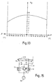
- Fig. 13
- ein Diagramm Stabilisierungsmoment um die Hochachse über dem Knickwinkel (zu Fig. 3 und 4),
- Fig. 14
- ein Diagramm Stabilisierungsmoment um die Hochachse über dem Knickwinkel (zu Fig. 5 und 6),
- Fig. 15
- Hydraulikschaltplan.
- Fig. 1
- a joint damping device in plan view,
- Fig. 2
- a joint damping device in side view and partial section,
- Fig. 3
- an alternative of a joint damping device in plan view,
- Fig. 4
- an alternative of a joint damping device in side view and partial section,
- Fig. 5
- the joint damping device according to the invention in plan view,
- Fig. 6
- the joint damping device according to the invention in side view and partial section,
- Fig. 7
- a schematic representation of an articulated bus
- Fig. 8
- a triangle of forces to the swivel,
- Fig. 9
- a diagram with F Q over KW,
- Fig. 10
- 1 shows a diagram of the cylinder stroke and piston speed over the buckling angle (for FIGS. 1 and 2),
- Fig. 11
- 1 shows a diagram of the stabilizing moment about the vertical axis over the articulation angle (for FIGS. 1 and 2),
- Fig. 12
- a diagram of cylinder stroke and piston speed over the articulation angle (to FIGS. 3 and 4),
- Fig. 13
- 1 shows a diagram of the stabilizing moment about the vertical axis over the bending angle (for FIGS. 3 and 4),
- Fig. 14
- 1 shows a diagram of the stabilizing moment about the vertical axis over the bending angle (for FIGS. 5 and 6),
- Fig. 15
- Hydraulic circuit diagram.
Die eigentliche Erfindung ist in den Fig. 5 und 6 gezeigt. Die Fig. 1 bis 4 und ihre begleitenden Diagramme dienen dem Verständnis der Erfindung, indem sie Problem und Lösung konturieren.The actual invention is shown in FIGS. 5 and 6. 1 to 4 and their accompanying diagrams serve to understand the invention by outlining the problem and the solution.
Fig. 1 zeigt eine Gelenkdämpfungsvorrichtung an einem Gelenkomnibus, wobei der Vorderwagen 3 mit dem Nachläufer 6 über einen Drehkranz 1 verbunden ist. Zwischen dem Vorderwagen 3 und dem über Drehgelenke 7 mit dem Nachläufer 6 verbundenen Drehkranzaußenring 1' ist in der Längsmittelebene des Fahrzeuges ein Hydraulikzylinder 2 oder Stoßdämpfer 2' angeordnet, der über Dreh- oder Kugelgelenk 4 am Drehkranzaußenring 1' und über Dreh- oder Kugelgelenk 5 am Vorderwagen 3 angebunden ist. Bei Geradeausfahrt, d.h., im gestreckten Zustand des Vorderwagens 3 und Nachläufers 6 nimmt der Hydraulikzylinder 2 oder Stoßdämpfer 3 seine innere Totlage ein, d.h., Kolbenhub, Dämpfungskraft und Dämpfungsmoment sind gleich 0.1 shows a joint damping device on an articulated bus, the
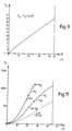
Mit zunehmendem Knickwinkel β vergrößert sich die aus Antriebskraft FA und Knickwinkel β resultierende Querkraft FQ gemäß FQ = FA sin β (siehe Fig. 7, 8 und 9). Aus der Fig. 10 ist der Hubverlauf (H) sowie der Verlauf der Hubgeschwindigkeit Vb bei zwei verschiedenen Konstanten Knickwinkelgeschwindigkeiten zu ersehen, wobei
![]()
![]()
Fig. 11 zeigt das Dämpfungsmoment M bei zwei verschiedenen Konstanten Knickwinkelgeschwindigkeiten unter Zugrundelegung einer Kraft FA = 30.000 N, wobei![]()
![]()
Die Fig. 3 und 4 zeigen eine andere Gelenkdämpfungsvorrichtung eines Gelenkomnibusses, wobei der Vorderwagen 3 mit dem Nachläufer 6 über einen Drehkranz 1 verbunden ist. Zwischen dem Vorderwagen 3 und dem über Drehgelenke 7 mit dem Nachläufer 6 verbundenen Drehkranzaußenring 1' ist ein Hydraulikzylinder 19 oder Stoßdämpfer 19' derart angeordnet, daß er einenendes über ein Dreh- oder Kugelgelenk 5 schwenkbar am Vorderwagen 3 und anderenendes über ein Dreh- oder Kugelgelenk 4 mit dem Drehkranzaußenteil 1', unterhalb des Drehkranzes in Quermittelebene angebracht, verbunden ist, wobei der Zylinder 19 oder der Stoßdämpfer 19' im Abstand, vorzugsweise in leichter Schräglage, zur Längsmittelebene des Fahrzeuges angeordnet ist und der Hydraulikzylinder 19 oder Stoßdämpfer 19' sich bei Strecklage des Fahrzeuges in der mittleren Hubstellung befindet.3 and 4 show another joint damping device of an articulated bus, the
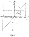
Gemäß Fig. 12 sind Kolbenhub H und Kolbengeschwindigkeit Vb über dem Knickwinkel β aufgetragen, wobei sich bei Strecklage des Gelenkzuges der Zylinder- oder Dämpferkolben in seiner mittleren Hubstellung befindet. Die Kolbengeschwindigkeit geht dabei nicht durch 0 und ist annähernd eine Gerade, wobei![]()
![]()
![]()
![]()
Aus Fig. 13 ist das entsprechende Dämpfungsmoment M zu ersehen.
Die Fig. 5 und 6 zeigen die erfindungsgemäße Gelenkdämpfungsvorrichtung an einem Gelenkomnibus, die eine Kombination der Systeme nach den Fig. 1, 2 und 3, 4 darstellt. Hierbei wird ein Hydraulikzylinder 2 oder Stoßdämpfer 2' in seiner speziellen Anordnung mit einem Hydraulikzylinder 19 oder Stoßdämpfer 19' in seiner speziellen Anordnung parallel geschaltet, so daß eine Dämpfungsmomentcharakteristik gemäß der Fig. 14 erzielt wird, wobei das Dämpfungsmoment schon in der Strecklage des Fahrzeuges einen gewissen Betrag aufweist und später in einen progressiven Kurvenverlauf übergeht, der den höheren Dämpfungsanforderungen bei steigendem Knickwinkel gerecht wird.5 and 6 show the joint damping device according to the invention on an articulated bus, which represents a combination of the systems according to FIGS. 1, 2 and 3, 4. Here, a
Die Kurve gemäß Fig. 14 resultiert aus einer Überlagerung der Kurven aus den Fig. 11 und 13.The curve according to FIG. 14 results from a superimposition of the curves from FIGS. 11 and 13.
Selbstverständlich kann der Verlauf des Stabilisierungsmomentes durch Verändern der Drosselquerschnitte oder der Anlenkpunkte des Hydraulikzylinders 19 oder des Stoßdämpfers 19' derart verändert werden, daß beiderseits der Ordinate die Kurvenäste symmetrisch verlaufen.Of course, the course of the stabilizing torque can be changed by changing the throttle cross sections or the articulation points of the
In der Anordnung des Stabilisierungsgelenkes gemäß den Fig. 5 und 6 mit dem dazugehörigen Verlauf des Dämpfungsmomentes nach Fig. 14 ist die praxisgerechte Optimierung des erfinderischen Systems zu sehen, indem nämlich schon in der Strecklage des Gelenkzuges beim Ausknicken ein gewisses Dämpfungsmoment aufgebaut ist, das einem "Schwänzeln" des Fahrzeuges entgegenwirkt und bei größerem Knickwinkel adäquat dem Ausknickrisiko das Dämpfungsmoment progressiv zunimmt.The arrangement of the stabilizing joint according to FIGS. 5 and 6 with the associated course of the damping torque according to FIG. 14 shows the practical optimization of the system according to the invention, namely that a certain damping moment is built up in the extended position of the joint pull when buckling Counteracts "wagging" of the vehicle and, with a larger articulation angle, the damping torque increases progressively in relation to the risk of articulation.
Die Fig. 15 zeigt einen Hydraulikschaltplan mit einem Zylinder 2, 19, der an seinen Enden Anschlüsse 10 und 11 aufweist, die durch eine Leitung 9 verbunden sind. Im weiteren Verlauf der Leitung 9 sind auf parallelen Verbindungssträngen verstellbare Drosselventile 12 und 13 angeordnet. Jeweils ein Strang ist beaufschlagbar, da zwischen den Strängen gegeneinandergeschaltete Absperrventile 14, 15 eingebaut sind, zwischen denen eine Leitung verläuft, in der ein Überdruckventil 16 eingebaut ist. Zum Ausgleich von Leckverlusten und unterschiedlichen Hubvolumina ist im System ein Druckspeicher 18 eingebaut. Bei Anordnung eines Drosselventiles, z.B. 12 kann dieses zur Modifizierung des Dämpfungsmomentes benutzt werden, während bei Anordnung von zwei Drosseln 12 und 13 diese sowohl zur Modifizierung des Dämpfungsmomentes dienen können, gleichwohl aber auch die Aufgabe haben, bei einer Ausführung des Gelenkstabilisierungssystems nach den Fig. 3 und 4 sowie 5 und 6 auf einen Ausgleich zwischen den unterschiedlichen Kolbenflächen eingestellt zu werden. Mit Hilfe des Absperrventiles 17 kann eine in verschiedenen Situationen wünschenswerte Konstantdämpfung eingeschaltet werden, deren Betrag sich über das Druckbegrenzungsventil 16 einstellen läßt. Die Zuschaltung des Absperrventiles 17 kann in der Gefahrensituation vom Fahrer per Hand über eine entsprechende Drucktaste erfolgen oder automatisch durch ein ABS/ASR-System eingesteuert werden.FIG. 15 shows a hydraulic circuit diagram with a
Die vorstehend dargestellten Ausführungsarten sind als Einzelanordnung beschrieben, sie können aber auch wie in den Ansprüchen dargestellt, als redundantes System ausgeführt werden, wobei man dann entweder den Vorteil von schlankeren Zylindern hat oder eben ein redundantes System erhält, das während des Fahrbetriebes nicht ausfallen kann.The embodiments described above are described as a single arrangement, but they can also be designed as a redundant system, as shown in the claims, in which case either one has the advantage of slimmer cylinders or one obtains a redundant system that cannot fail during driving operation.
- 11
- DrehkranzSlewing ring
- 1'1'
- DrehkranzaußenringSlewing ring outer ring
- 1''1''
- DrehkranzinnenringInner ring
- 22nd
- HydraulikzylinderHydraulic cylinder
- 2'2 '
- StoßdämpferShock absorber
- 33rd
- VorderwagenFront end
- 44th
- Dreh- oder Kugelgelenk am DrehkranzSwivel or ball joint on the slewing ring
- 55
- Dreh- oder Kugelgelenk am FahrzeugSwivel or ball joint on the vehicle
- 66
- NachläuferFollower
- 77
- DrehgelenkeSwivel joints
- 88th
- DrehgelenkmitteSwivel center
- 99
- VerbindungsleitungConnecting line
- 1010th
- Anschluß von 2, 19Connection of 2, 19
- 1111
- Anschluß von 2, 19Connection of 2, 19
- 1212
- DrosselventilThrottle valve
- 1313
- DrosselventilThrottle valve
- 1414
- Rückschlagventilcheck valve
- 1515
- Rückschlagventilcheck valve
- 1616
- ÜberdruckventilPressure relief valve
- 1717th
- AbsperrventilShut-off valve
- 1818th
- DruckspeicherPressure accumulator
- 1919th
- HydraulikzylinderHydraulic cylinder
- 19'19 '
- StoßdämpferShock absorber
- BB
- KnickwinkelKink angle
- aa
- Radius (Kolbenanlenkpunkt-Drehkranzmitte)Radius (center of the piston pivot point)
- H = bx-bmin H = w x -b min
- Kolbenhub bzw. H = bx - bmittel Piston stroke or H = b x - b medium
- FA F A
- AntriebskraftDriving force
- FV F V
- Schubkraft am VorderwagenThrust on the front end
- FQ F Q
- QuerkraftShear force
- Vb V b
- KolbenhubgeschwindigkeitPiston stroke speed
- MM
- Stabilisierungsmoment um die HochachseStabilizing moment around the vertical axis
- ff
- DämpfungsfaktorDamping factor
- Vβ V β
- KnickwinkelgeschwindigkeitBuckling angle speed
Claims (9)
- An articulated damping device for use in an articulated bus having a leading carriage (3), and a trailing carriage (6) connected thereto by means of a swivelling joint (1), at least one hydraulic cylinder or damper being arranged between the two carriages (3, 6), characterised in that a hydraulic cylinder (2) or a damper (2'), located at its inner dead centre position when the articulated bus is in its straight position, is arranged between the leading carriage (3) and the trailing carriage (6) connected to the outer ring (1') of the swivelling joint or between the trailing carriage (6) and the leading carriage (3) connected to the inner ring (1'') of the swivelling joint in the longitudinal median plane of the articulated bus, and a further hydraulic cylinder (19) or damper (19') is arranged in parallel with the hydraulic cylinder (2) or the damper (2') and is located in its central stroke position, preferably slightly tilted, and at a distance from the longitudinal median plane of the articulated bus when the articulated bus is in its straight position, wherein the hydraulic cylinder (19) or damper (19') is attached in a pivotable manner at one end to the respective carriage (3, 6) and at the other end in the transverse median plane of the respective swivelling joint component (1, 1', 1'').
- An articulated damping device according to claim 1, characterised in that a respective hydraulic cylinder (2) or damper (2') is arranged between the leading carriage (3) and its corresponding swivelling joint component, and also between the trailing carriage (6) and its corresponding swivelling joint component in the longitudinal median plane of the articulated bus in such a way that it is located at its inner dead centre position when the articulated bus is in its straight position, and a further hydraulic cylinder (19) or damper (19') is arranged hydraulically in parallel therewith, preferably slightly tilted, and at a distance from the longitudinal median plane of the articulated bus, and is located in its central stroke position when the articulated bus is in its straight position, wherein the hydraulic cylinder (19) or damper (19') is attached in a pivotable manner at one end to the respective carriage (3, 6) and at the other end in the transverse median plane of the respective swivelling joint component (1, 1', 1'').
- An articulated damping device according to claim 1 or 2, characterised in that an adjustable throttle valve (12) is arranged in the connection duct (9) between the points of attachment (10, 11) of the displacement areas of the hydraulic cylinder (2, 19).
- An articulated damping device according to claims 1 to 3, characterised in that in the connection duct (9) between the connection points (10, 11) of the hydraulic cylinder (2, 19), an adjustable throttle valve (12, 13) is allocated to each connection point (10, 11), and the other connection point respectively is blocked by a check valve (14, 15).
- An articulated damping device according to one or more of claims 1 to 4, characterised in that a plurality of parallel-connected throttle valves (12, 13) of different throttle cross-section are arranged in a duct (9) and the different throttle valves can be adjusted to different ranges of the turning angle.
- An articulated damping device according to one or more of claims 1 to 5, characterised in that a shut-off valve (17) is arranged in the connection duct (9) between the cylinder connections (10, 11) and in its locked position prevents the displacement volume from being drained via the throttle valves and thus achieves a constant damping over the entire turning angle range.
- An articulated damping device according to claim 6, characterised in that the shut-off valve (17) can be automatically switched on by an anti-lock system or automatic slip control.
- An articulated damping device according to one or more of claims 1 to 7, characterised in that when dampers (2', 19') are used, known dampers with damping characteristics differing over the stroke path are used.
- An articulated damping device according to one or more of claims 1 to 8, characterised in that when dampers (19') are used, they have one or more grooves on one or more stroke areas in a known manner, in order to achieve less damping.
Priority Applications (1)
| Application Number | Priority Date | Filing Date | Title |
|---|---|---|---|
| AT90103823T ATE90290T1 (en) | 1989-04-14 | 1990-02-27 | JOINT STABILIZATION SYSTEM. |
Applications Claiming Priority (2)
| Application Number | Priority Date | Filing Date | Title |
|---|---|---|---|
| DE3912383A DE3912383C1 (en) | 1989-04-14 | 1989-04-14 | |
| DE3912383 | 1989-04-14 |
Publications (3)
| Publication Number | Publication Date |
|---|---|
| EP0392177A2 EP0392177A2 (en) | 1990-10-17 |
| EP0392177A3 EP0392177A3 (en) | 1991-08-28 |
| EP0392177B1 true EP0392177B1 (en) | 1993-06-09 |
Family
ID=6378730
Family Applications (1)
| Application Number | Title | Priority Date | Filing Date |
|---|---|---|---|
| EP90103823A Expired - Lifetime EP0392177B1 (en) | 1989-04-14 | 1990-02-27 | Stabilized vehicle articulation system |
Country Status (5)
| Country | Link |
|---|---|
| US (1) | US5137107A (en) |
| EP (1) | EP0392177B1 (en) |
| AT (1) | ATE90290T1 (en) |
| DE (2) | DE3912383C1 (en) |
| HU (1) | HU209913B (en) |
Families Citing this family (13)
| Publication number | Priority date | Publication date | Assignee | Title |
|---|---|---|---|---|
| DE4007684A1 (en) * | 1990-03-10 | 1991-09-12 | Man Nutzfahrzeuge Ag | JOINT DAMPING DEVICE ON JOINT COMBUSES |
| DE4118612A1 (en) * | 1991-06-06 | 1992-12-10 | Man Nutzfahrzeuge Ag | SYNCHRONOUS DAMPER DEVICE |
| DE4139992C1 (en) * | 1991-12-04 | 1993-04-01 | Man Nutzfahrzeuge Ag, 8000 Muenchen, De | |
| BE1006915A3 (en) * | 1993-03-10 | 1995-01-24 | Hool Nv | Articulated bus. |
| HU213562B (en) * | 1993-12-23 | 1997-08-28 | Autoipari Kutato Fejlesztoe | Device for influencing articulation angle of articulated vehicle, mainly bus |
| US5957476A (en) * | 1996-02-28 | 1999-09-28 | Simpson; William A. | Anti-jackknife system for tractor-trailers |
| DE29822472U1 (en) * | 1998-12-18 | 1999-04-01 | Huebner Gummi & Kunststoff | Hydraulic system for damping the rotary movement of a swivel joint between two vehicle parts of an articulated vehicle, e.g. an articulated bus |
| DE10000744C2 (en) * | 2000-01-04 | 2002-05-29 | Hartmut Lorenz | Trailer coupling with anti-roll damping |
| DE10130530C1 (en) * | 2001-06-25 | 2002-12-12 | Weidemann Oswald | Hydraulic damping device for damping vibrations between the chassis parts of a center pivot steered vehicle comprises an autonomous vibration damper hinged to the central articulated |
| ATE242138T1 (en) * | 2001-09-17 | 2003-06-15 | Voith Turbo Scharfenberg Gmbh | JOINT ARRANGEMENT |
| EP2738071B1 (en) * | 2012-11-30 | 2015-08-12 | Hübner GmbH & Co. KG | Articulated vehicle with a joint between the vehicle sections |
| US10131380B1 (en) | 2014-07-15 | 2018-11-20 | Jack Simmons | Vertically articulating vehicle |
| US11490559B2 (en) * | 2017-07-21 | 2022-11-08 | Perma-Green Supreme, Inc. | Steering assistance systems, roll control systems, and vehicles having the same |
Family Cites Families (24)
| Publication number | Priority date | Publication date | Assignee | Title |
|---|---|---|---|---|
| US2843417A (en) * | 1955-06-20 | 1958-07-15 | Karl Kassbohrer G M B H | Connecting means for the vehicles of link-trains |
| US2896734A (en) * | 1957-09-27 | 1959-07-28 | Allis Chalmers Mfg Co | Hydraulic steering system for jointed vehicles |
| DE1191847B (en) * | 1959-06-19 | 1965-04-29 | Eugen Cramer Dipl Ing | Articulated rail trolleys |
| FR1305153A (en) * | 1960-11-17 | 1962-09-28 | Power steering mechanism | |
| US3176801A (en) * | 1962-10-12 | 1965-04-06 | Northrop Corp | Precision motion control device |
| GB1268932A (en) * | 1969-03-06 | 1972-03-29 | Simms Group Res Dev Ltd | Improvements in or relating to braking apparatus |
| US3877347A (en) * | 1973-03-13 | 1975-04-15 | Res Engineering Company | Hydraulic control |
| DE2420203B2 (en) * | 1974-04-26 | 1979-07-12 | Hamburger Hochbahn Ag, 2000 Hamburg | Device for protecting an articulated road vehicle against excessive buckling |
| DE2748713C2 (en) * | 1977-10-29 | 1986-11-27 | Daimler-Benz Ag, 7000 Stuttgart | Device for influencing the articulation angle for an articulated pull |
| JPS55114648A (en) * | 1979-02-06 | 1980-09-04 | Lucas Industries Ltd | Hydraulic pressure actuating antiskiddbrake system |
| DD155312A5 (en) * | 1979-08-21 | 1982-06-02 | Autoipari Kutato Intezet | DEVICE FOR INFLUENCING THE KNUCKLE ANGLE FOR JOINT ARMS |
| US4588171A (en) * | 1981-12-18 | 1986-05-13 | Applied Power Inc. | Shock absorber and air spring assembly |
| GR79630B (en) * | 1982-08-18 | 1984-10-31 | Falkenried Fahrzeug Gmbh | |
| DE3302790A1 (en) * | 1983-01-28 | 1984-08-09 | Fa. Albert Schnetz, 8000 München | HYDRAULIC LIMIT DAMPER |
| DE3405871A1 (en) * | 1983-02-19 | 1984-08-30 | Daimler-Benz Ag, 7000 Stuttgart | Anti-jackknifing control |
| DE3305751A1 (en) * | 1983-02-19 | 1984-08-30 | Daimler-Benz Ag, 7000 Stuttgart | KIND PROTECTION CONTROL |
| DE3414257C2 (en) * | 1984-04-14 | 1993-12-02 | Bosch Gmbh Robert | Spring element with variable hardness for vehicles |
| IT1174114B (en) * | 1984-05-30 | 1987-07-01 | Umberto Vigliani | ARTICULATION WITH NON-CONVENTIONAL TROLLEY WITH INDEPENDENT WHEELS FOR VEHICLES ON LOW-FLOOR RAIL |
| US4681335A (en) * | 1986-03-06 | 1987-07-21 | J. I. Case Company | Center pivot hitch assembly |
| DE3610937A1 (en) * | 1986-04-02 | 1987-10-08 | Bosch Gmbh Robert | DEVICE FOR DAMPING MOTION PROCESSES |
| DE3615071A1 (en) * | 1986-05-03 | 1987-11-05 | Daimler Benz Ag | Kink protection device for articulated vehicles |
| DE3623655A1 (en) * | 1986-07-12 | 1988-01-28 | Man Nutzfahrzeuge Gmbh | KINK PROTECTION DEVICE FOR ROAD VEHICLES |
| US4819770A (en) * | 1987-06-22 | 1989-04-11 | Rite-Hite Corporation | Hydraulic control device |
| US4890684A (en) * | 1988-04-22 | 1990-01-02 | Simmons-Rand Company | Articulated vehicle with hinged joint |
-
1989
- 1989-04-14 DE DE3912383A patent/DE3912383C1/de not_active Expired - Fee Related
-
1990
- 1990-02-27 EP EP90103823A patent/EP0392177B1/en not_active Expired - Lifetime
- 1990-02-27 DE DE9090103823T patent/DE59001656D1/en not_active Expired - Fee Related
- 1990-02-27 AT AT90103823T patent/ATE90290T1/en active
- 1990-03-08 HU HU901360A patent/HU209913B/en not_active IP Right Cessation
- 1990-03-13 US US07/492,764 patent/US5137107A/en not_active Expired - Fee Related
Also Published As
| Publication number | Publication date |
|---|---|
| HU901360D0 (en) | 1990-05-28 |
| DE59001656D1 (en) | 1993-07-15 |
| DE3912383C1 (en) | 1990-06-28 |
| HUT58225A (en) | 1992-02-28 |
| US5137107A (en) | 1992-08-11 |
| HU209913B (en) | 1994-11-28 |
| EP0392177A2 (en) | 1990-10-17 |
| EP0392177A3 (en) | 1991-08-28 |
| ATE90290T1 (en) | 1993-06-15 |
Similar Documents
| Publication | Publication Date | Title |
|---|---|---|
| EP0392177B1 (en) | Stabilized vehicle articulation system | |
| DE3031862C2 (en) | Articulated vehicle with several axles | |
| DE19714485A1 (en) | Steering for a multi-axle vehicle | |
| DD203706A5 (en) | STABILIZATION DEVICE FOR VEHICLE AXLES | |
| EP0446614B1 (en) | Articulation damping device for articulated buses | |
| EP0122956B1 (en) | Stabilising device for road trains with fifth wheel traction couplings and for articulated vehicles | |
| DE3305751C2 (en) | ||
| DE3743203A1 (en) | Wheel-guide unit | |
| EP3263428A1 (en) | Technique for air circulation of a semitrailer | |
| DE3204577A1 (en) | HULL CHASSIS WITH TANDEM ARRANGEMENT OF WHEELS | |
| DE19727289A1 (en) | Emergency vehicle, especially fire engine, for road and rail operations | |
| DE102006004930A1 (en) | With a towing vehicle via a gooseneck detachable heavy load vehicle | |
| DE3543085A1 (en) | FRAME-LIKE, FLEXIBLE AXLE SUSPENSION SYSTEM | |
| DE2741125A1 (en) | TRUCKS, ESPECIALLY LARGE SPACE VEHICLES OR SEMITRAILERS | |
| EP0518208B1 (en) | Device for changing over the steering of a self-propelling crane | |
| EP2239188B1 (en) | Goose-neck for a vehicle, especially for a heavy duty vehicle | |
| DE3441964C2 (en) | Brake pressure control unit | |
| DE2263506A1 (en) | CONTROL DEVICE FOR A TRAILED CAR | |
| EP3094527B1 (en) | Semi-trailer landing gear | |
| DE4137382C1 (en) | Utility site-work vehicle - is articulated with fixed wheels on front carriage and steering wheels on rear carriage. | |
| DE2913424C2 (en) | ||
| DE2927736A1 (en) | DEVICE FOR DISTRIBUTING THE WEIGHT OF A TRAIN VEHICLE BY MEANS OF AN ADDITIONAL LOAD | |
| DE3540880C2 (en) | ||
| DE102009028641A1 (en) | Steering device for vehicle axle, comprises four steering elements, which are work-connected with one another, where two steering elements are coupled with vehicle axle in area of their free ends | |
| DE19949152A1 (en) | Hydropneumatic suspension |
Legal Events
| Date | Code | Title | Description |
|---|---|---|---|
| PUAI | Public reference made under article 153(3) epc to a published international application that has entered the european phase |
Free format text: ORIGINAL CODE: 0009012 |
|
| AK | Designated contracting states |
Kind code of ref document: A2 Designated state(s): AT CH DE FR GB IT LI NL SE |
|
| PUAL | Search report despatched |
Free format text: ORIGINAL CODE: 0009013 |
|
| AK | Designated contracting states |
Kind code of ref document: A3 Designated state(s): AT CH DE FR GB IT LI NL SE |
|
| 17P | Request for examination filed |
Effective date: 19910912 |
|
| 17Q | First examination report despatched |
Effective date: 19920723 |
|
| GRAA | (expected) grant |
Free format text: ORIGINAL CODE: 0009210 |
|
| ITF | It: translation for a ep patent filed |
Owner name: DE DOMINICIS & MAYER S.R.L. |
|
| AK | Designated contracting states |
Kind code of ref document: B1 Designated state(s): AT CH DE FR GB IT LI NL SE |
|
| REF | Corresponds to: |
Ref document number: 90290 Country of ref document: AT Date of ref document: 19930615 Kind code of ref document: T |
|
| REF | Corresponds to: |
Ref document number: 59001656 Country of ref document: DE Date of ref document: 19930715 |
|
| ET | Fr: translation filed | ||
| GBT | Gb: translation of ep patent filed (gb section 77(6)(a)/1977) |
Effective date: 19930722 |
|
| PGFP | Annual fee paid to national office [announced via postgrant information from national office to epo] |
Ref country code: CH Payment date: 19931227 Year of fee payment: 5 |
|
| PGFP | Annual fee paid to national office [announced via postgrant information from national office to epo] |
Ref country code: SE Payment date: 19931229 Year of fee payment: 5 |
|
| PGFP | Annual fee paid to national office [announced via postgrant information from national office to epo] |
Ref country code: AT Payment date: 19940125 Year of fee payment: 5 |
|
| PGFP | Annual fee paid to national office [announced via postgrant information from national office to epo] |
Ref country code: DE Payment date: 19940209 Year of fee payment: 5 |
|
| PGFP | Annual fee paid to national office [announced via postgrant information from national office to epo] |
Ref country code: GB Payment date: 19940217 Year of fee payment: 5 |
|
| PLBE | No opposition filed within time limit |
Free format text: ORIGINAL CODE: 0009261 |
|
| STAA | Information on the status of an ep patent application or granted ep patent |
Free format text: STATUS: NO OPPOSITION FILED WITHIN TIME LIMIT |
|
| 26N | No opposition filed | ||
| EAL | Se: european patent in force in sweden |
Ref document number: 90103823.2 |
|
| PG25 | Lapsed in a contracting state [announced via postgrant information from national office to epo] |
Ref country code: GB Effective date: 19950227 Ref country code: AT Effective date: 19950227 |
|
| PG25 | Lapsed in a contracting state [announced via postgrant information from national office to epo] |
Ref country code: SE Effective date: 19950228 Ref country code: LI Effective date: 19950228 Ref country code: CH Effective date: 19950228 |
|
| GBPC | Gb: european patent ceased through non-payment of renewal fee |
Effective date: 19950227 |
|
| PG25 | Lapsed in a contracting state [announced via postgrant information from national office to epo] |
Ref country code: DE Effective date: 19951101 |
|
| EUG | Se: european patent has lapsed |
Ref document number: 90103823.2 |
|
| PGFP | Annual fee paid to national office [announced via postgrant information from national office to epo] |
Ref country code: FR Payment date: 19970114 Year of fee payment: 8 |
|
| PGFP | Annual fee paid to national office [announced via postgrant information from national office to epo] |
Ref country code: NL Payment date: 19970130 Year of fee payment: 8 |
|
| PG25 | Lapsed in a contracting state [announced via postgrant information from national office to epo] |
Ref country code: FR Free format text: THE PATENT HAS BEEN ANNULLED BY A DECISION OF A NATIONAL AUTHORITY Effective date: 19980228 |
|
| PG25 | Lapsed in a contracting state [announced via postgrant information from national office to epo] |
Ref country code: NL Free format text: LAPSE BECAUSE OF NON-PAYMENT OF DUE FEES Effective date: 19980901 |
|
| NLV4 | Nl: lapsed or anulled due to non-payment of the annual fee |
Effective date: 19980901 |
|
| REG | Reference to a national code |
Ref country code: FR Ref legal event code: ST |
|
| PG25 | Lapsed in a contracting state [announced via postgrant information from national office to epo] |
Ref country code: IT Free format text: LAPSE BECAUSE OF NON-PAYMENT OF DUE FEES;WARNING: LAPSES OF ITALIAN PATENTS WITH EFFECTIVE DATE BEFORE 2007 MAY HAVE OCCURRED AT ANY TIME BEFORE 2007. THE CORRECT EFFECTIVE DATE MAY BE DIFFERENT FROM THE ONE RECORDED. Effective date: 20050227 |