EP0391237B1 - Strahlungsdetektor - Google Patents
Strahlungsdetektor Download PDFInfo
- Publication number
- EP0391237B1 EP0391237B1 EP90105949A EP90105949A EP0391237B1 EP 0391237 B1 EP0391237 B1 EP 0391237B1 EP 90105949 A EP90105949 A EP 90105949A EP 90105949 A EP90105949 A EP 90105949A EP 0391237 B1 EP0391237 B1 EP 0391237B1
- Authority
- EP
- European Patent Office
- Prior art keywords
- reflecting
- radiation detector
- reflecting layers
- layers
- binder
- Prior art date
- Legal status (The legal status is an assumption and is not a legal conclusion. Google has not performed a legal analysis and makes no representation as to the accuracy of the status listed.)
- Expired - Lifetime
Links
- 230000005855 radiation Effects 0.000 title claims description 25
- 239000013078 crystal Substances 0.000 claims description 28
- 239000011230 binding agent Substances 0.000 claims description 21
- 239000003795 chemical substances by application Substances 0.000 claims description 18
- TZCXTZWJZNENPQ-UHFFFAOYSA-L barium sulfate Chemical compound [Ba+2].[O-]S([O-])(=O)=O TZCXTZWJZNENPQ-UHFFFAOYSA-L 0.000 claims description 12
- 229920000178 Acrylic resin Polymers 0.000 claims description 11
- 239000004925 Acrylic resin Substances 0.000 claims description 11
- 239000002245 particle Substances 0.000 claims description 10
- GWEVSGVZZGPLCZ-UHFFFAOYSA-N Titan oxide Chemical compound O=[Ti]=O GWEVSGVZZGPLCZ-UHFFFAOYSA-N 0.000 claims description 4
- NLHHRLWOUZZQLW-UHFFFAOYSA-N Acrylonitrile Chemical compound C=CC#N NLHHRLWOUZZQLW-UHFFFAOYSA-N 0.000 claims description 2
- 229920002319 Poly(methyl acrylate) Polymers 0.000 claims description 2
- XTXRWKRVRITETP-UHFFFAOYSA-N Vinyl acetate Chemical compound CC(=O)OC=C XTXRWKRVRITETP-UHFFFAOYSA-N 0.000 claims description 2
- BZHJMEDXRYGGRV-UHFFFAOYSA-N Vinyl chloride Chemical compound ClC=C BZHJMEDXRYGGRV-UHFFFAOYSA-N 0.000 claims description 2
- PNEYBMLMFCGWSK-UHFFFAOYSA-N aluminium oxide Inorganic materials [O-2].[O-2].[O-2].[Al+3].[Al+3] PNEYBMLMFCGWSK-UHFFFAOYSA-N 0.000 claims description 2
- 229910052593 corundum Inorganic materials 0.000 claims description 2
- CPLXHLVBOLITMK-UHFFFAOYSA-N magnesium oxide Inorganic materials [Mg]=O CPLXHLVBOLITMK-UHFFFAOYSA-N 0.000 claims description 2
- 229920001485 poly(butyl acrylate) polymer Polymers 0.000 claims description 2
- 229920000120 polyethyl acrylate Polymers 0.000 claims description 2
- 229910001845 yogo sapphire Inorganic materials 0.000 claims description 2
- 150000001252 acrylic acid derivatives Chemical class 0.000 claims 1
- 229920001577 copolymer Polymers 0.000 claims 1
- 229920001296 polysiloxane Polymers 0.000 description 8
- 239000000853 adhesive Substances 0.000 description 7
- 230000005251 gamma ray Effects 0.000 description 7
- 239000003973 paint Substances 0.000 description 7
- 239000004372 Polyvinyl alcohol Substances 0.000 description 6
- 229920002451 polyvinyl alcohol Polymers 0.000 description 6
- 230000001070 adhesive effect Effects 0.000 description 5
- 239000011347 resin Substances 0.000 description 5
- 229920005989 resin Polymers 0.000 description 5
- 229920000642 polymer Polymers 0.000 description 4
- 238000004299 exfoliation Methods 0.000 description 3
- 238000004519 manufacturing process Methods 0.000 description 3
- 239000000463 material Substances 0.000 description 3
- 238000005259 measurement Methods 0.000 description 3
- FVAUCKIRQBBSSJ-UHFFFAOYSA-M sodium iodide Chemical compound [Na+].[I-] FVAUCKIRQBBSSJ-UHFFFAOYSA-M 0.000 description 3
- 239000004809 Teflon Substances 0.000 description 2
- 229920006362 Teflon® Polymers 0.000 description 2
- NIXOWILDQLNWCW-UHFFFAOYSA-N acrylic acid group Chemical group C(C=C)(=O)O NIXOWILDQLNWCW-UHFFFAOYSA-N 0.000 description 2
- 239000007864 aqueous solution Substances 0.000 description 2
- XJHCXCQVJFPJIK-UHFFFAOYSA-M caesium fluoride Chemical compound [F-].[Cs+] XJHCXCQVJFPJIK-UHFFFAOYSA-M 0.000 description 2
- XQPRBTXUXXVTKB-UHFFFAOYSA-M caesium iodide Chemical compound [I-].[Cs+] XQPRBTXUXXVTKB-UHFFFAOYSA-M 0.000 description 2
- 238000001514 detection method Methods 0.000 description 2
- 238000010586 diagram Methods 0.000 description 2
- 238000002845 discoloration Methods 0.000 description 2
- 239000003822 epoxy resin Substances 0.000 description 2
- 150000002148 esters Chemical class 0.000 description 2
- 239000000203 mixture Substances 0.000 description 2
- 229920000647 polyepoxide Polymers 0.000 description 2
- 230000035945 sensitivity Effects 0.000 description 2
- 101100008049 Caenorhabditis elegans cut-5 gene Proteins 0.000 description 1
- 239000001856 Ethyl cellulose Substances 0.000 description 1
- ZZSNKZQZMQGXPY-UHFFFAOYSA-N Ethyl cellulose Chemical compound CCOCC1OC(OC)C(OCC)C(OCC)C1OC1C(O)C(O)C(OC)C(CO)O1 ZZSNKZQZMQGXPY-UHFFFAOYSA-N 0.000 description 1
- 229920002125 Sokalan® Polymers 0.000 description 1
- WUOACPNHFRMFPN-UHFFFAOYSA-N alpha-terpineol Chemical compound CC1=CCC(C(C)(C)O)CC1 WUOACPNHFRMFPN-UHFFFAOYSA-N 0.000 description 1
- 230000004075 alteration Effects 0.000 description 1
- OYLGJCQECKOTOL-UHFFFAOYSA-L barium fluoride Chemical compound [F-].[F-].[Ba+2] OYLGJCQECKOTOL-UHFFFAOYSA-L 0.000 description 1
- 229910001632 barium fluoride Inorganic materials 0.000 description 1
- 229910052797 bismuth Inorganic materials 0.000 description 1
- JCXGWMGPZLAOME-UHFFFAOYSA-N bismuth atom Chemical compound [Bi] JCXGWMGPZLAOME-UHFFFAOYSA-N 0.000 description 1
- WUKWITHWXAAZEY-UHFFFAOYSA-L calcium difluoride Chemical compound [F-].[F-].[Ca+2] WUKWITHWXAAZEY-UHFFFAOYSA-L 0.000 description 1
- 229910001634 calcium fluoride Inorganic materials 0.000 description 1
- 239000011248 coating agent Substances 0.000 description 1
- 238000000576 coating method Methods 0.000 description 1
- 238000007334 copolymerization reaction Methods 0.000 description 1
- SQIFACVGCPWBQZ-UHFFFAOYSA-N delta-terpineol Natural products CC(C)(O)C1CCC(=C)CC1 SQIFACVGCPWBQZ-UHFFFAOYSA-N 0.000 description 1
- 239000006185 dispersion Substances 0.000 description 1
- 238000001035 drying Methods 0.000 description 1
- 239000000839 emulsion Substances 0.000 description 1
- 229920001249 ethyl cellulose Polymers 0.000 description 1
- 235000019325 ethyl cellulose Nutrition 0.000 description 1
- 230000009969 flowable effect Effects 0.000 description 1
- LNEPOXFFQSENCJ-UHFFFAOYSA-N haloperidol Chemical compound C1CC(O)(C=2C=CC(Cl)=CC=2)CCN1CCCC(=O)C1=CC=C(F)C=C1 LNEPOXFFQSENCJ-UHFFFAOYSA-N 0.000 description 1
- 239000007788 liquid Substances 0.000 description 1
- 238000000034 method Methods 0.000 description 1
- 239000003960 organic solvent Substances 0.000 description 1
- 229920000058 polyacrylate Polymers 0.000 description 1
- 239000004584 polyacrylic acid Substances 0.000 description 1
- 229920005596 polymer binder Polymers 0.000 description 1
- 239000002491 polymer binding agent Substances 0.000 description 1
- 239000000843 powder Substances 0.000 description 1
- 230000001681 protective effect Effects 0.000 description 1
- 238000009877 rendering Methods 0.000 description 1
- 238000011160 research Methods 0.000 description 1
- 235000009518 sodium iodide Nutrition 0.000 description 1
- 239000007787 solid Substances 0.000 description 1
- 239000002904 solvent Substances 0.000 description 1
- 239000007921 spray Substances 0.000 description 1
- 239000000126 substance Substances 0.000 description 1
- 229920003002 synthetic resin Polymers 0.000 description 1
- 239000000057 synthetic resin Substances 0.000 description 1
- 229940116411 terpineol Drugs 0.000 description 1
- 229920002803 thermoplastic polyurethane Polymers 0.000 description 1
- XLYOFNOQVPJJNP-UHFFFAOYSA-N water Substances O XLYOFNOQVPJJNP-UHFFFAOYSA-N 0.000 description 1
Images


Classifications
-
- G—PHYSICS
- G01—MEASURING; TESTING
- G01T—MEASUREMENT OF NUCLEAR OR X-RADIATION
- G01T1/00—Measuring X-radiation, gamma radiation, corpuscular radiation, or cosmic radiation
- G01T1/16—Measuring radiation intensity
- G01T1/20—Measuring radiation intensity with scintillation detectors
- G01T1/202—Measuring radiation intensity with scintillation detectors the detector being a crystal
-
- G—PHYSICS
- G01—MEASURING; TESTING
- G01T—MEASUREMENT OF NUCLEAR OR X-RADIATION
- G01T1/00—Measuring X-radiation, gamma radiation, corpuscular radiation, or cosmic radiation
- G01T1/16—Measuring radiation intensity
- G01T1/20—Measuring radiation intensity with scintillation detectors
- G01T1/2002—Optical details, e.g. reflecting or diffusing layers
Definitions
- This invention relates to a radiation detector used in high energy physics or diagnostic radiology such as a X-ray computerized tomographic apparatus (X-ray CT) and a positron emission nuclide tomographic apparatus (positron CT).
- X-ray CT X-ray computerized tomographic apparatus
- positron CT positron emission nuclide tomographic apparatus
- a radiation detector having a photomultiplier tube and a scintillator generates scintillation light by irradiated radiation and then the photons of the light are detected by the photomultiplier tube.
- the scintillator thus is required to meet the following conditions:
- the conventional radiation detector uses, as the reflecting layers of Bi4Ge3O12 crystal (referred to as "BGO crystal” ), BaSO4 with a binder consisting of polyvinyl alcohol (referred to as "PVA binder").
- BGO crystal Bi4Ge3O12 crystal
- PVA binder polyvinyl alcohol
- a further prior art device is disclosed in US-A-4 543 485, which relates to a radiation detector comprising a photomultiplier tube, a scintillator crystal, such as a bismuth germanate (BGO) crystal, a face of which contacts the photomultiplier tube, and having a light reflective layer on faces other than the contacting face.
- the light reflective layer contains a powdery reflective agent dispersed in an organic binder such as ethyl cellulose, or an organic solvent such as terpineol.
- a synthetic resin such as an epoxy resin, an acrylic resin, or an urethane resin may be used as a protective outer layer of the radiation detector.
- the European patent application EP-A-0 146 255 discloses a formable light reflective composition which may be used as a radiation detector comprising a resin containing light-reflective solid particles having sizes of from 0.001 to 20 ⁇ m. Different flowable and curable resins comprising also polyacrylates may be used, but silicone type resins are preferred.
- This composition is used as a light reflective layer for preparing a radiation detector with sodium iodide, caesium fluoride, caesium iodide, barium fluoride and calcium fluoride as scintillation crystal.
- the reflecting layers are made into multiple layers from aqueous solutions of different concentration of PVA mingled with BaSO4 to be repeatedly coated thereon so many time that the process is onerous and expensive.
- This invention made to resolve such problematical points is intended to offer a radiation detector which meets the requirements of the scintillator, improves the reflecting properties and adhesiveness of the reflecting layers and can be readily manufactured. This is achieved by providing a radiation detector as defined in Claim 1.
- the inventors found that the mean particle size of the reflecting agent has a significant influence upon the reflectance of the layers.
- the radiation detector of this invention has a photomultiplier tube 1, a Bi4Ge3O12 crystal 2 and reflecting layers 3.
- the reflecting layer 3 contains a reflecting agent and an acrylic resin type binder which are provided on surfaces other than the face of the crystal 2 contacted to the photomultiplier tube 1.
- the contacting face of the crystal is mirror polished and the other surfaces ore rough polished
- the mean particle size of the reflecting agent is preferably not less than 0.8 ⁇ m and that the binder is a polymer type binder.
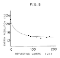
- the thickness of the reflecting layers 3 is preferably 50 ⁇ m or more.
- the mean particle sizes of the reflecting agent in the reflecting layers are more than 0.8 ⁇ m so that the reflecting layers enhance the reflectance. This implies a greater number of photons which reach the photomultiplier tube and better energy resolution. If the mean sizes are less than this value, the energy resolution will be increased as described later, which in turn worsens the sensitivity of the radiation detector.
- polymer type binder more specifically an acrylic resin
- the thickness of the layers which is more than 50 ⁇ m, permits to obtain small enough an energy resolution. If the thickness of the layers is not more than 50 ⁇ m, the scintillation in the BGO crystal leaks through the reflecting layers thereby rendering it impossible to have low enough an energy resolution.
- the radiation detector of this invention presents a high enough sensitivity with its energy resolution 16% or less.
- the reflecting agents used are known materials such as BaSO4, TiO2, Al2O3, MgO and the like. Since the energy resolution increases if the mean particle sizes of these reflecting agents are 0.8 ⁇ m or less. 0.8 ⁇ m or more of size, more preferably 0.8 to 2.5 ⁇ m thus is to be chosen.
- acrylic resin based synthetic paints as polymer type binder enables to retain scintillation value of BGO crystal 2 as well as excellent adhesion and hardly allows crack. It does not permit such discoloration of paint film as in case of epoxy resins. Further use of silicone-based binder to adhere the BGO crystal 2 onto the photomultiplier tube 1 can avoid permeation of the binder and such trouble as exfoliation of the reflecting layers 3.
- the acrylic resins used are known materials such as polyacrylic acid esters: for instance, polymethylacrylate, polyethylacrylate, polybutylacrylate; emulsions and solvents which are of copolymerization type of these esters with acrylonitrile, vinyl acetate, vinyl chloride and the like.
- the reflecting layers 3 are 50 ⁇ m or less in thickness, this thickness should be not less than 50 ⁇ m, more preferably 50 ⁇ m to 200 ⁇ m.
- the reflecting layers 3 may be overlaid with Teflon (Trade name; made by Du Pont Corporation) tape having reflective power.
- Teflon tape may be used Teflon tape as changing from reflecting layers containing reflecting powder agents and acrylic resins.
- FIG. 1 is a perspective illustration showing a working example of this invention
- FIG. 2 is a block diagram showing a system of measurement
- FIG. 3 represents a characteristic curve showing a relationship between a number of incidence ⁇ -ray and pulse height generated by the ⁇ -ray
- FIG. 4 is a characteristic diagram showing the relationship between mean particle sizes of the reflecting layers and an energy resolution in the working example
- FIG. 5 is another characteristic curve showing the relationship between the thickness of the reflecting layers and the energy resolution in the working example.
- 1 represents a photomultiplier tube
- 2 represents Bi4Ge3O12 crystal in rectangular parallelepiped form (referred to as BGO crystal) contacted to the entrance window 1a of the photomultiplier tube 1
- 3 represents reflecting layers of the BGO crystal 2 provided on faces other than a face contacted to the photomultiplier tube 1.
- the reflecting layers 3 consist of a reflecting agent and a polymer type binder.
- a paint of reflecting agent was prepared by mixing one volume part of liquid dispersion consisting of 1kg of powdered reflecting agent, 500g of water and 60g of 2.6% PVA aqueous solution and another one volume part of an acrylic type resin (NIPPEI HOME PAINT, a brand of NIPPON PAINT K. K.). This paint was coated on the five rough-polished faces by a means of a spray gun. After drying up the coated paint, the reflecting layers 3 were obtained on the 5 faces of the BGO crystal 2.
- an acrylic type resin as binder made it possible to have such layers by only once coating.
- the mirror polished face of this BGO crystal 2 was contacted to the photomultiplier tube 1 as shown in FIG. 1.
- a measuring system for an energy resolution of the above scintillator was build up as shown in FIG. 2.
- the energy resolution of the scintillator was then measured by using the system.
- the light generated by radiation of ⁇ -ray 4 irradiated onto the BGO crystal 2 was received and transferred to photo-electron by the photomultiplier tube 1.
- the photo-electron was amplified by the preamplifier 5 and the amplifier 6. Then the number of photons generated was counted up with the counter 7.
- the number 8 in the figure represents an electric source.
- pulse height produced per incidence ⁇ -ray was plotted on coordinate with the pulse height by incidence of the ⁇ - ray taken on an abscissa and the number of the incidence ⁇ -ray on the ordinate.
- FIG. 4 shows the results of measurement of this energy resolution using a wide variety of reflecting agents and varying the mean particle size thereof.
- the mean size of the agent is 0.8 ⁇ m or larger
- the energy resolution indicates a value 16% or less, which implies a good luminous efficiency and that the resolution is well stable.
- FIG. 5 indicates the result of measurement of energy resolution, made using BaSO4, 1 ⁇ m in mean particle size and varying the thickness of the reflecting layers 3.
- the energy resolution increases if the thickness is less than 50 ⁇ m, but it takes a stable value of less than 16% when the thickness is more than 50 ⁇ m. It was observed that any of these reflecting layers caused to grow no exfoliation nor crack.
- the BGO crystals 2 having the reflecting layers thus obtained were adhered with each other through intermediary of the layers with commonly used silicone-based adhesive "KE420" (brand of THE SHIN-ETSU CHEMICAL) and then assembled into a radiation detector. No exfoliation of the reflecting layers nor increased energy resolution was recognized.
- KE420 brand of THE SHIN-ETSU CHEMICAL
- the energy resolution of the radiation detector by this invention can be made smaller and stable by taken not less than 0.8 ⁇ m of the mean particle sizes of the reflecting agent that forms the reflecting layers provided on Bi4Ge3O12 crystal faces other than a face contacted to the entrance window of the photomultiplier tube, radiation can be detected with high accuracy.
- the detection accuracy can be improved since the energy resolution caused to be reduced and stabilized by raising the thickness of reflecting layers up to 50 ⁇ m or more.
- a binder for forming the reflecting layers of high polymer binder, more specifically acrylic resins, is effective in eliminating the influence of the silicone-based adhesive agent, which allows to enhance the reflectance and adhesion of the reflecting layers.
- a processing once suffices to build the reflecting layers thus resolving the problem of intricate manufacturing.
- a radiation detector comprising a photomultiplier tube, a Bi4Ge3O12 crystal of which a face contacted to the photomultiplier tube and reflecting layers which essentially consisting of reflecting powdery agent and an acrylic resin type binder provided on faces other than the face of the crystal, the energy resolution can be made smaller and stable. Thus, the resolution of the detector can be made higher.
- the detection accuracy can be improved since the energy resolution caused to be reduced and stabilized by raising the thickness of reflecting layers up to 50 ⁇ m or more.
- an acrylic resin, as a binder for forming the reflecting layers is effective in eliminating the influence of the silicone-based adhesive agent, which allows to enhance the reflectance and adhesion of the reflecting layers.
- a processing once suffices to build the reflecting layers thus resolving the problem of intricate manufacturing.
Landscapes
- Physics & Mathematics (AREA)
- Health & Medical Sciences (AREA)
- Life Sciences & Earth Sciences (AREA)
- General Physics & Mathematics (AREA)
- High Energy & Nuclear Physics (AREA)
- Molecular Biology (AREA)
- Spectroscopy & Molecular Physics (AREA)
- Chemical & Material Sciences (AREA)
- Crystallography & Structural Chemistry (AREA)
- Measurement Of Radiation (AREA)
- Electron Tubes For Measurement (AREA)
Claims (5)
- Strahlungsdetektor, umfassend eine Photoverstärkerröhre (1), einen vielflächigen Bi₄Ge₃O₁₂-Kristall (2), von dem eine Fläche mit der Photoverstärkerröhre in Kontakt ist und Reflexionsschichten (3), enthaltend ein pulverförmiges Reflexionsmittel und ein Bindemittel auf Flächen, die sich von der Kontaktfläche unterscheiden, dadurch gekennzeichnet, daß die Kontaktfläche spiegelpoliert ist und die anderen Oberflächen grobpoliert sind und das Bindemittel ein Acrylharz enthält.
- Strahlungsdetektor nach Anspruch 1, dadurch gekennzeichnet, daß das pulverförmige Reflexionsmittel eine mittlere Teilchengröße von 0,8 bis 2,5 µm besitzt.
- Strahlungsdetektor nach Anspruch 1, dadurch gekennzeichnet, daß das pulverförmige Reflexionsmittel mindestens eines ist, ausgewählt aus BaSO₄, TiO₂, Al₂O₃ und MgO.
- Strahlungsdetektor nach Anspruch 1, dadurch gekennzeichnet, daß das Acrylharz mindestens eines ist, ausgewählt aus Polymethylacrylat, Polyethylacrylat, Polybutylacrylat und Copolymeren von Acrylnitril, Vinylacetat und Vinylchlorid mit diesen Acrylaten.
- Strahlungsdetektor nach Anspruch 1, dadurch gekennzeichnet, daß die Dicke der Reflexionsschichten (3) nicht geringer als 50 µm ist.
Applications Claiming Priority (2)
| Application Number | Priority Date | Filing Date | Title |
|---|---|---|---|
| JP1086793A JPH02266287A (ja) | 1989-04-07 | 1989-04-07 | 放射線検出器 |
| JP86793/89 | 1989-04-07 |
Publications (2)
| Publication Number | Publication Date |
|---|---|
| EP0391237A1 EP0391237A1 (de) | 1990-10-10 |
| EP0391237B1 true EP0391237B1 (de) | 1993-07-21 |
Family
ID=13896660
Family Applications (1)
| Application Number | Title | Priority Date | Filing Date |
|---|---|---|---|
| EP90105949A Expired - Lifetime EP0391237B1 (de) | 1989-04-07 | 1990-03-28 | Strahlungsdetektor |
Country Status (4)
| Country | Link |
|---|---|
| US (1) | US5061855A (de) |
| EP (1) | EP0391237B1 (de) |
| JP (1) | JPH02266287A (de) |
| DE (1) | DE69002265T2 (de) |
Families Citing this family (20)
| Publication number | Priority date | Publication date | Assignee | Title |
|---|---|---|---|---|
| EP0535634B1 (de) * | 1991-10-03 | 1998-06-10 | Kabushiki Kaisha Toshiba | Strahlungsdetektor und Methode seiner Herstellung |
| JP3220245B2 (ja) * | 1992-08-10 | 2001-10-22 | 浜松ホトニクス株式会社 | 光電子増倍管 |
| JPH06103959A (ja) * | 1992-09-21 | 1994-04-15 | Hamamatsu Photonics Kk | 光電子増倍管の集合装置 |
| DE4301177A1 (de) * | 1993-01-19 | 1994-07-21 | Telefunken Microelectron | UV-Strahlungsdetektor |
| DE4327752A1 (de) * | 1993-08-18 | 1995-02-23 | Taurus Daten & Mestechnik Gmbh | Strahlungsmeßgerät zur Lumineszenz- und Fluoreszenzmessung |
| FR2718852B1 (fr) * | 1994-04-19 | 1996-05-15 | Commissariat Energie Atomique | Dispositif de détection à distance de rayonnement. |
| US5483070A (en) * | 1994-08-02 | 1996-01-09 | Packard Instrument Company | Scintillation counter |
| US7157014B1 (en) * | 2001-10-05 | 2007-01-02 | Cit Pet Systems, Inc. | Method for producing a high resolution detector array |
| US20030178570A1 (en) * | 2002-03-25 | 2003-09-25 | Hitachi Metals, Ltd. | Radiation detector, manufacturing method thereof and radiation CT device |
| US7420162B2 (en) * | 2004-06-30 | 2008-09-02 | Siemens Medical Solutions Usa, Inc. | Systems and methods for creating stable camera optics |
| DE102005035421A1 (de) * | 2005-07-28 | 2007-02-08 | Siemens Ag | Formbares und aushärtendes Reflektormaterial mit erhöhter Reflektivität |
| US7780912B2 (en) * | 2005-08-26 | 2010-08-24 | Lawrence Livermore National Security, Llc | Paint for detection of radiological or chemical agents |
| JP2009264751A (ja) * | 2008-04-21 | 2009-11-12 | Furukawa Co Ltd | シンチレータの製造方法、シンチレータ、シンチレータ用塗布液、これを調製する方法 |
| JP5317675B2 (ja) * | 2008-12-22 | 2013-10-16 | 株式会社東芝 | 放射線検出器およびその製造方法 |
| US9310323B2 (en) | 2009-05-16 | 2016-04-12 | Rapiscan Systems, Inc. | Systems and methods for high-Z threat alarm resolution |
| GB201312352D0 (en) * | 2013-07-10 | 2013-08-21 | Rapiscan Systems Ltd | Radiation detection |
| US9557427B2 (en) | 2014-01-08 | 2017-01-31 | Rapiscan Systems, Inc. | Thin gap chamber neutron detectors |
| FR3057073B1 (fr) * | 2016-09-30 | 2021-05-07 | Damavan Imaging | Dispositif et systeme de detection de rayonnements ionisants et de neutrons |
| CN112540395A (zh) * | 2020-12-04 | 2021-03-23 | 清远先导材料有限公司 | 闪烁晶体阵列及其组装方法和拆卸方法 |
| DE102022213891A1 (de) | 2022-12-19 | 2024-06-20 | Robert Bosch Gesellschaft mit beschränkter Haftung | Überwachungsvorrichtung |
Family Cites Families (7)
| Publication number | Priority date | Publication date | Assignee | Title |
|---|---|---|---|---|
| NL7802916A (nl) * | 1978-03-17 | 1979-09-19 | Philips Nv | Stralendetektorinrichting. |
| US4375423A (en) * | 1980-07-15 | 1983-03-01 | General Electric Company | Index-matched phosphor scintillator structures |
| US4543485A (en) * | 1981-11-24 | 1985-09-24 | Hitachi Chemical Company, Ltd. | Scintillator for radiation detection and process for producing the same |
| US4647781A (en) * | 1983-01-31 | 1987-03-03 | Hitachi Chemical Company, Ltd. | Gamma ray detector |
| US4533489A (en) * | 1983-12-07 | 1985-08-06 | Harshaw/Filtrol Partnership | Formable light reflective compositions |
| US4733088A (en) * | 1985-09-02 | 1988-03-22 | Hitachi, Ltd. | Radiation detector |
| US4788436A (en) * | 1986-12-24 | 1988-11-29 | Walter Koechner | Radiation sensitive optical fiber and detector |
-
1989
- 1989-04-07 JP JP1086793A patent/JPH02266287A/ja active Granted
-
1990
- 1990-03-28 DE DE90105949T patent/DE69002265T2/de not_active Expired - Fee Related
- 1990-03-28 EP EP90105949A patent/EP0391237B1/de not_active Expired - Lifetime
- 1990-04-09 US US07/506,864 patent/US5061855A/en not_active Expired - Lifetime
Also Published As
| Publication number | Publication date |
|---|---|
| JPH02266287A (ja) | 1990-10-31 |
| DE69002265D1 (de) | 1993-08-26 |
| JPH0575991B2 (de) | 1993-10-21 |
| US5061855A (en) | 1991-10-29 |
| DE69002265T2 (de) | 1993-11-25 |
| EP0391237A1 (de) | 1990-10-10 |
Similar Documents
| Publication | Publication Date | Title |
|---|---|---|
| EP0391237B1 (de) | Strahlungsdetektor | |
| CA2619931C (en) | Paint for detection of corrosion and warning of chemical and radiological attack | |
| US20130221229A1 (en) | Adhesive layer for digital detectors | |
| US4543485A (en) | Scintillator for radiation detection and process for producing the same | |
| JP2565278B2 (ja) | 放射線検出器 | |
| US4066908A (en) | Well-type scintillation assembly | |
| US4631409A (en) | Scintillator crystal having a highly reflective surface | |
| US20130092828A1 (en) | Scintillation detection device with pressure sensitive adhesive interfaces | |
| EP2920612B1 (de) | Digitaler radiografiedetektor | |
| EP0129109B1 (de) | Flaches Strahlungsmessgerät | |
| US4179614A (en) | Thermoluminescent dosimeter system | |
| WO2000077545A1 (en) | In-situ radioactivity detection | |
| JP5655030B2 (ja) | 放射性物質に直面していることを警告するシステム及び方法 | |
| KR20040028565A (ko) | 신틸레이션 검출기 | |
| JP2000258539A (ja) | 放射線検出装置及び方法 | |
| CN109313950A (zh) | 放射线图像转换屏和平板探测器 | |
| JPS63129304A (ja) | 発光効率の高いシンチレ−タ−フアイバ− | |
| JP2000235078A (ja) | 放射線検出用構造体と、それを用いた放射線検出器および放射線検査装置 | |
| EP0752711B1 (de) | Antistatischer Verstärkungsschirm für Röntgenstrahlen mit Fluoroalkylsulfonat-Salzen | |
| EP3391089A1 (de) | Szintillationsvorrichtung mit feuchtigkeitsbarriere | |
| JPS6114474B2 (de) | ||
| JPH03239786A (ja) | シンチレータおよびシンチレータを用いた放射線検出器 | |
| EP0127168B1 (de) | Verfahren zur Messung der Stralungsintensität | |
| DE60000949T2 (de) | Druckmessgeräte ausgestattet mit tribostimulierbarem Speicherleuchtstoff | |
| KR100639418B1 (ko) | 알파 입자 탐지용 박막 형태의 ZnS(Ag) 섬광 검출소재 및 그의 제조 방법 |
Legal Events
| Date | Code | Title | Description |
|---|---|---|---|
| PUAI | Public reference made under article 153(3) epc to a published international application that has entered the european phase |
Free format text: ORIGINAL CODE: 0009012 |
|
| AK | Designated contracting states |
Kind code of ref document: A1 Designated state(s): DE FR GB |
|
| 17P | Request for examination filed |
Effective date: 19910321 |
|
| 17Q | First examination report despatched |
Effective date: 19920225 |
|
| GRAA | (expected) grant |
Free format text: ORIGINAL CODE: 0009210 |
|
| AK | Designated contracting states |
Kind code of ref document: B1 Designated state(s): DE FR GB |
|
| ET | Fr: translation filed | ||
| REF | Corresponds to: |
Ref document number: 69002265 Country of ref document: DE Date of ref document: 19930826 |
|
| PLBE | No opposition filed within time limit |
Free format text: ORIGINAL CODE: 0009261 |
|
| STAA | Information on the status of an ep patent application or granted ep patent |
Free format text: STATUS: NO OPPOSITION FILED WITHIN TIME LIMIT |
|
| 26N | No opposition filed | ||
| PGFP | Annual fee paid to national office [announced via postgrant information from national office to epo] |
Ref country code: FR Payment date: 19990309 Year of fee payment: 10 |
|
| PGFP | Annual fee paid to national office [announced via postgrant information from national office to epo] |
Ref country code: GB Payment date: 19990401 Year of fee payment: 10 |
|
| PGFP | Annual fee paid to national office [announced via postgrant information from national office to epo] |
Ref country code: DE Payment date: 19990406 Year of fee payment: 10 |
|
| PG25 | Lapsed in a contracting state [announced via postgrant information from national office to epo] |
Ref country code: GB Free format text: LAPSE BECAUSE OF NON-PAYMENT OF DUE FEES Effective date: 20000328 |
|
| GBPC | Gb: european patent ceased through non-payment of renewal fee |
Effective date: 20000328 |
|
| PG25 | Lapsed in a contracting state [announced via postgrant information from national office to epo] |
Ref country code: FR Free format text: LAPSE BECAUSE OF NON-PAYMENT OF DUE FEES Effective date: 20001130 |
|
| REG | Reference to a national code |
Ref country code: FR Ref legal event code: ST |
|
| PG25 | Lapsed in a contracting state [announced via postgrant information from national office to epo] |
Ref country code: DE Free format text: LAPSE BECAUSE OF NON-PAYMENT OF DUE FEES Effective date: 20010103 |