EP0390770B1 - Méthode de correction électronique d'erreur de position pour un système de mesure incrémentiel et système de mesure pour mettre en oeuvre ce procédé - Google Patents
Méthode de correction électronique d'erreur de position pour un système de mesure incrémentiel et système de mesure pour mettre en oeuvre ce procédé Download PDFInfo
- Publication number
- EP0390770B1 EP0390770B1 EP90890081A EP90890081A EP0390770B1 EP 0390770 B1 EP0390770 B1 EP 0390770B1 EP 90890081 A EP90890081 A EP 90890081A EP 90890081 A EP90890081 A EP 90890081A EP 0390770 B1 EP0390770 B1 EP 0390770B1
- Authority
- EP
- European Patent Office
- Prior art keywords
- measuring system
- correction
- measuring
- divider
- selector switch
- Prior art date
- Legal status (The legal status is an assumption and is not a legal conclusion. Google has not performed a legal analysis and makes no representation as to the accuracy of the status listed.)
- Expired - Lifetime
Links
Images

Classifications
-
- G—PHYSICS
- G01—MEASURING; TESTING
- G01D—MEASURING NOT SPECIALLY ADAPTED FOR A SPECIFIC VARIABLE; ARRANGEMENTS FOR MEASURING TWO OR MORE VARIABLES NOT COVERED IN A SINGLE OTHER SUBCLASS; TARIFF METERING APPARATUS; MEASURING OR TESTING NOT OTHERWISE PROVIDED FOR
- G01D5/00—Mechanical means for transferring the output of a sensing member; Means for converting the output of a sensing member to another variable where the form or nature of the sensing member does not constrain the means for converting; Transducers not specially adapted for a specific variable
- G01D5/12—Mechanical means for transferring the output of a sensing member; Means for converting the output of a sensing member to another variable where the form or nature of the sensing member does not constrain the means for converting; Transducers not specially adapted for a specific variable using electric or magnetic means
- G01D5/244—Mechanical means for transferring the output of a sensing member; Means for converting the output of a sensing member to another variable where the form or nature of the sensing member does not constrain the means for converting; Transducers not specially adapted for a specific variable using electric or magnetic means influencing characteristics of pulses or pulse trains; generating pulses or pulse trains
- G01D5/24471—Error correction
- G01D5/2449—Error correction using hard-stored calibration data
-
- G—PHYSICS
- G01—MEASURING; TESTING
- G01D—MEASURING NOT SPECIALLY ADAPTED FOR A SPECIFIC VARIABLE; ARRANGEMENTS FOR MEASURING TWO OR MORE VARIABLES NOT COVERED IN A SINGLE OTHER SUBCLASS; TARIFF METERING APPARATUS; MEASURING OR TESTING NOT OTHERWISE PROVIDED FOR
- G01D5/00—Mechanical means for transferring the output of a sensing member; Means for converting the output of a sensing member to another variable where the form or nature of the sensing member does not constrain the means for converting; Transducers not specially adapted for a specific variable
- G01D5/12—Mechanical means for transferring the output of a sensing member; Means for converting the output of a sensing member to another variable where the form or nature of the sensing member does not constrain the means for converting; Transducers not specially adapted for a specific variable using electric or magnetic means
- G01D5/244—Mechanical means for transferring the output of a sensing member; Means for converting the output of a sensing member to another variable where the form or nature of the sensing member does not constrain the means for converting; Transducers not specially adapted for a specific variable using electric or magnetic means influencing characteristics of pulses or pulse trains; generating pulses or pulse trains
- G01D5/24471—Error correction
- G01D5/24485—Error correction using other sensors
-
- G—PHYSICS
- G05—CONTROLLING; REGULATING
- G05B—CONTROL OR REGULATING SYSTEMS IN GENERAL; FUNCTIONAL ELEMENTS OF SUCH SYSTEMS; MONITORING OR TESTING ARRANGEMENTS FOR SUCH SYSTEMS OR ELEMENTS
- G05B19/00—Programme-control systems
- G05B19/02—Programme-control systems electric
- G05B19/18—Numerical control [NC], i.e. automatically operating machines, in particular machine tools, e.g. in a manufacturing environment, so as to execute positioning, movement or co-ordinated operations by means of programme data in numerical form
- G05B19/19—Numerical control [NC], i.e. automatically operating machines, in particular machine tools, e.g. in a manufacturing environment, so as to execute positioning, movement or co-ordinated operations by means of programme data in numerical form characterised by positioning or contouring control systems, e.g. to control position from one programmed point to another or to control movement along a programmed continuous path
- G05B19/21—Numerical control [NC], i.e. automatically operating machines, in particular machine tools, e.g. in a manufacturing environment, so as to execute positioning, movement or co-ordinated operations by means of programme data in numerical form characterised by positioning or contouring control systems, e.g. to control position from one programmed point to another or to control movement along a programmed continuous path using an incremental digital measuring device
-
- G—PHYSICS
- G05—CONTROLLING; REGULATING
- G05B—CONTROL OR REGULATING SYSTEMS IN GENERAL; FUNCTIONAL ELEMENTS OF SUCH SYSTEMS; MONITORING OR TESTING ARRANGEMENTS FOR SUCH SYSTEMS OR ELEMENTS
- G05B2219/00—Program-control systems
- G05B2219/30—Nc systems
- G05B2219/37—Measurements
- G05B2219/37296—Electronic graduation, scale expansion, interpolation
-
- G—PHYSICS
- G05—CONTROLLING; REGULATING
- G05B—CONTROL OR REGULATING SYSTEMS IN GENERAL; FUNCTIONAL ELEMENTS OF SUCH SYSTEMS; MONITORING OR TESTING ARRANGEMENTS FOR SUCH SYSTEMS OR ELEMENTS
- G05B2219/00—Program-control systems
- G05B2219/30—Nc systems
- G05B2219/41—Servomotor, servo controller till figures
- G05B2219/41092—References, calibration positions for correction of value position counter
Definitions
- the invention relates to a method for the electronic correction of position errors in an incremental measuring system, in particular an incremental length measuring system, according to the preamble of claim 1.
- the invention also relates to an incremental measuring system according to the preamble of patent claim 2.
- the correspondingly designed incremental scale is scanned according to optoelectronic, capacitive, inductive or magnetic scanning principles, the evaluation usually being supplied with two measurement signals phase-shifted by 90 °, in which the length of a signal train usually corresponds to a division increment of the scale.
- the measuring graduation preferably consists of light and dark fields of the same width, which are scanned using the same graduation, but with mutually displaced fractions of the scanning grids using assigned lighting devices and photoelectric receivers.
- four photoelectric receivers are preferably used, connected in pairs in counter-connection.
- Another divider circuit is known from CH-A-650 334, in which the analog measurement signals are modulated with alternating voltages of higher frequency, which are obtained by means of a system clock and coasters and pulse formers, a fixed division factor being set via the coasters and a changeover to other subdivision factors is possible by switching the converter. A number of pulses corresponding to the phase angle of the measurement signal and thus to the currently scanned divisional fraction of the incremental division is generated and counted into a counting device. This enables an electronic subdivision of the scale increment by the fixed division factor, for example 100.
- Position errors result primarily from division errors of the measuring division, assembly errors of a length measuring system on an assigned machine and / or also from machine errors themselves. Further (mostly linear) measuring errors result from a different thermal expansion behavior of a length scale having the measuring division compared to a machine bed and a not exactly parallel one Arrangement of the scale in relation to the assigned guidance of a machine.
- the scannable correction template is formed from a link chain attached along a linear scale, which can be adjusted on the joints via eccentrics that can be actuated from the outside.
- a constant correction is possible with these mechanical correction methods.
- the corrections are limited by the possible adjustment path of the scanning unit relative to the driver, in particular when larger linear measurement errors occur and by the spacing of the setting points for the correction template, that is, they are not possible to any extent.
- the mechanical correction is extremely complex, requires a much larger housing for the measuring system and also a relatively large scanning unit with the necessary actuators and a correspondingly large mass and can in principle only be used if the measuring system is inherently used to carry out such mechanical corrections was built and designed.
- Stepless corrections for linear scale errors can be achieved when using metal scales by stretching or compressing the scale body, but here too there is considerable effort and a significant restriction in the design freedom for the creation of the measuring system.
- the object of the invention is to provide a method for the electronic correction of position errors, by simple means without changing the scale and the scanning unit Corrections can be made without counting jumps or equivalent measurement errors occurring at the correction points, whereby an almost infinitely variable correction curve is to be made possible, the correction range is not limited and the corrections can be freely programmed if necessary.
- a partial object of the invention is to provide an incremental measuring system according to the preamble of claim 2, which is suitable for making corrections according to the new method.
- the main task is solved by the features or method steps specified in claim 1.
- the essence of the invention is that correction steps take place electronically, the size of which is only a fraction of a counting step, so that the disadvantages mentioned at the outset are completely avoided.
- the method according to the invention can be used both with divider circuits and with other divider stages, e.g. B. with divider stages according to CH-A-650 334 equipped measuring systems. In the latter case, a higher division factor can be selected for the determination of the correction steps than is inherently necessary for the generation of the counting pulses.
- the corrections are carried out in such a way that a counting step is triggered at the correction point if the correction condition per se is given, the counting step for the correction corresponding to the normal counting step plus or minus the correction step.
- the subtask is solved by a measuring system according to claim 2.
- the device used for error correction can be fitted in place of the single divider circuit, which is usually provided externally anyway, the output signals being processed further, just like those of a single divider circuit.
- the one when switching from a divider circuit the next correction step that occurs again corresponds to the fraction of a counting step given by the number of divider circuits and can be kept negligibly small. Since the subdivision factor remains the same in the divider circuits, there are sufficiently large phase distances to the next tap point at the tapping points of a divider circuit and the evaluation device does not need to be changed.
- the electronically achievable sensitive correction in only a fraction of a counting step is comparable to the known mechanical correction, but it has the advantage over this that the correction curve, which according to the method according to the invention or in the specific case by switching to the different divider circuits can be adhered to, if necessary, can be adapted to each error curve by appropriate programming of the circuit of the selector switch.
- analog switches can be used which select and switch on the divider circuits, which usually consist of resistor chains, with which the sufficiency is found with common trigger and pulse shaper stages.
- trigger and pulse shaping stages form small and easily integrable modules, whereby it is even possible to combine the trigger stages with a divider circuit each.
- an embodiment according to claim 4 is advantageous, precise switchovers being possible even at high counting speeds and the number of switch connections to be made via the switch being reduced when using multiple divider chains.
- the evaluation units can include up-down counters, counting devices with free-running counters for the two adjustment directions, the respective status of which is recorded by a microcomputer and linked to previously stored values, and similar circuits.
- the evaluation units can proceed according to claim 5, so that the switch switches only at the predetermined level after the switching command to the following divider circuit. An additional possibility is specified in claim 6.
- a circuit according to claim 7 can be used, with a plurality of divider circuits also specifying in which direction the reversal takes place, ie. H. which of the two neighboring divider chains is switched on.
- Claim 8 specifies a possibility for correcting the temperature error. Any corrections can be made, the correction memory either being programmed with fixed memory values during manufacture, but also being freely programmable using an input device.
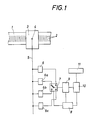
- a scale 1 preferably encapsulated in a housing, has a measuring graduation 2 consisting of light-dark fields.
- a scanning unit 3 can be adjusted via a driver, which has photoelectric receivers illuminated by the scale and scanning grids offset from one another by division fractions. at their outputs in their basic form sinusoidal, mutually phase-shifted analog measurement signals occur, normally at output 4 two 90 ° out-of-phase sinusoidal measurement signals appearing, which are fed via lines 5 shown only for further processing.
- Two or more divider circuits 6, 6a, 6b, 6c are connected in parallel to the lines 5.
- the number n of divider circuits used corresponds to the denominator of the fraction that indicates the size of the correction step in relation to a counting step.
- Each of the divider circuits 6 to 6c can be connected via an electronic switch 7, which is controlled by a control logic 8, to a downstream trigger and pulse shaper stage 9, where the signals sampled from the respectively connected divider circuit 6 to 6c when the scanning unit 3 is adjusted which result in corresponding trigger levels at the divider circuit, under electronic Subdivision of the scale division into electronic count signals are evaluated, which are fed to a processing unit, for example a counting device 10 with a downstream display device 11.
- the divider circuits 6 to 6c have the same division factors, but are offset with respect to the analog measurement signals with respect to their trigger levels by fractions of the division step, so that corrections for this correction step can be made by switching the switch 7.
- the switching direction of the switch 7 is determined here via the switching logic 8.
- the switching basically takes place immediately after tapping the last counting step from the previously switched-on divider circuit, the first trigger level obtained from the newly switched-on divider circuit being suppressed if a corresponding reduction in the counting steps by several Corrections should be achieved.
- the total display would then be displayed by one counting step less via four correction steps.
- four switches of switch 7, with divider stages 6 to 6c being switched on in succession would result in one more increment than if the position of switch 7 remained unchanged when the same scale distance was scanned.
- the switching logic 8 of the switch 7 can be controlled by a memory and by the control unit 10, so that any desired correction curve can be realized by selective switching in the two adjustment directions.
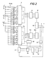
- a correction step the size of half a counting step is made possible using divider chains 6, 6b.
- the divider stages 6, 6b are designed as resistance divider chains, the divider stage 6 trigger points 0/18/36/54/72/90/108/126/144/162 el. Degrees and the divider chain 6b trigger points 9/27/45/63 / 81/99/117/135/153/171 el. Degrees determined.
- the electronic changeover switch 7, 7a in each case attaches a divider chain 6 or 6b to trigger stages 9, 9a, each of which is associated with logic logic with pulse shaper stages 12, 12a (shown separately here compared to the embodiment according to FIG. 1). If the analog switch 7, 7a is changed over from the divider chain 6 to the divider chain 6b, this means that if the switchover point is from 6 to 6b at the switchover point of 0 electrical degrees, the next trigger point is not at 18 electrical degrees but at 9 electrical degrees . Degree, or if this trigger point is suppressed by the switching logic, is 27 electrical degrees, ie a correction step is carried out by half a counting step.
- the control logic has a pulse quadruple circuit, known per se, which is connected via a switching logic 19 to the pulse shaper stages 12, 12a and has a directional discriminator 13, from which the direction-dependent counting pulses are fed to an up-down counter 14.
- the counter 14 is a counter with an adjustable partial ratio.
- a decoder stage with memory 15 is required, which can either be programmed via an input unit (not shown here) or is equipped with a pre-programmed read-only memory.
- the counter coding unit 14, 15 can also be formed by a computer with a read-only memory, into which correction points can be entered via an input unit or external interfaces.
- the signal obtained at the output of stage 14, 15 for triggering a correction step is processed in a synchronizing stage 16 in such a way that at the desired switching point (preferably at 0 or 9 el. degrees) a direction-dependent counting pulse is sent to an address counter 17 forming part of the switching logic 8 in order to advance the divider chains via the analog switches 7, 7a.
- each correction step will be assigned to a specific point of the periodic analog measurement signals and the correction step is preferably carried out at 0 degrees.
- This synchronization takes place in the synchronization stage 16, which triggers a counting step for the address counter 17 only when the condition mentioned is fulfilled.
- a release logic 18 has the effect that, at the switchover point at 0 or 9 electrical degrees, the individual divider stage 6 or 6b is only switched when the trigger point of the adjacent stage has been reached. At this point in time, a new switchover via the trigger output and the generation of a false pulse are avoided.
- the switching logic 19 already mentioned has the purpose of making it possible to use simple means to make successive corrections in the same direction, that is to say after corrective steps corresponding to a full counting step, to ensure the further processing of the signals without interference.
- the analog switches 7, 7a could each advance a full step by a full step after achieving a correction, that is to say z. B. switch the switch part previously connected to trigger point 0 or 9 to trigger point 36, 45, etc.
- the switchover logic 19 can be used to accomplish the same task with simpler means in the digital part of the circuit.
- the switching logic 19 is controlled by the address counter 17 and changes the connection of the pulse shaping stages 12, 12a with the outputs leading to further processing in accordance with the control signals.
- Circuit illustrates the analog signals occurring on the lines 5 and the derivation of the count signals T1, T2, T1 ', T2', from the tap of the divider chains when the two divider chains 6 and 6b are connected.
- a simplification of the circuit would be possible at least theoretically if exactly triangular analog signals are obtained for the analog measuring signals via the scanning unit 3 or a converter stage downstream of the scanning unit.
- the circuit 14, 15 is formed from a computer, one can compensate for external parameters and a linear error caused thereby, z. B. the thermal expansion error provide temperature sensors, which make appropriate corrections by periodically switching the switch 7, 7a.
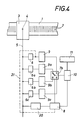
- each divider circuit 6 to 6c is also assigned a trigger and pulse shaper stage 9 to 9c, at the output of which digital count signals already occur, but which again relate to the Basic signals are offset by fractions of a counting step.
- the selector switch 7b is again controlled by the control logic 8 and is either synchronized to the analog measurement signals via a dedicated synchronization stage 20 on line 5 or, as indicated by dash-dotted lines via line 21, by connection to the output of one divider chain.
- the correction device according to the invention is primarily intended for length measuring systems, but can even be used in angle measuring systems or resolvers in which a fine-tuned mechanical correction has so far been used was impossible and corrections were only made if necessary by adding or suppressing counting steps.
Claims (9)
- Procédé de correction électronique d'erreurs de position dans un système de mesure incrémental, en particulier un système de mesure de longueur incrémental, dans lequel, par exploration d'une graduation de mesure (2) à l'aide d'une unité d'exploration (3), des signaux de mesure analogiques, périodiques, à forme de base sinusoïdale sont produits et dans lequel, à partir de ceux-ci, des signaux de comptage numériques (T₁, T₂) destinés à un dispositif d'exploitation (10, 11), dépendant du sens de réglage, sont dérivés, en vue d'obtenir une subdivision électronique de l'échelle graduée, chaque signal de comptage étant associé à une position de phase déterminée des signaux de mesure, caractérisé en ce que l'on détermine pour la correction d'erreurs, entre les niveaux de signaux présentant un décalage de phase par rapport aux endroits de subdivision et associés aux signaux de comptage (T₁, T₂), d'autres niveaux de signaux, décalés de la valeur de fractions définies du pas de division, et l'exploitation de la mesure effectuée suivant un programme de correction se référant à volonté aux niveaux de signaux décalés, de sorte que les corrections ne soient effectuées que dans des étapes de correction correspondant à des fractions du pas de la division.
- Système de mesure incrémental, dans lequel, par exploration d'une graduation de mesure (2), des signaux de mesure analogiques, à forme de base sinusoïdale, périodiques, produits à l'aide d'une unité d'exploration (3), sont amenés à un circuit diviseur (6) et, à partir d'eux, des signaux de comptage (T₁, T₂) numériques, dépendant du sens de déplacement de réglage, destinés à un dispositif d'exploitation (10, 11), par exemple un dispositif d'affichage ou de commande, sont dérivés par l'intermédiaire d'étages de déclenchement et de formation d'impulsion (9, 12), en opérant une subdivision électronique de la graduation de mesure (2), des dispositifs électroniques étant prévus pour la correction des erreurs,
caractérisé en ce que sont prévus pour la correction des erreurs deux ou plusieurs circuits diviseurs (6 à 6c), ayant chacun des facteurs de division égaux, mais avec des positions en phase des niveaux de déclenchement décalées les unes par rapport aux autres, de la valeur de fractions du pas de division, par rapport aux signaux de mesure analogiques et un interrupteur de sélection électronique (7, 7a, 7b), commandé suivant un programme de correction, étant chaque fois susceptible d'être mis en circuit avec le dispositif d'exploitation (10). - Système de mesure incrémental selon la revendication 2,
caractérisé en ce que l'interrupteur de sélection (7, 7a) est prévu entre les circuits diviseurs (6 à 6c) et les étages de déclenchement et de formation d'impulsion (9, 12) communs, associés au dispositif d'exploitation (10) - Système de mesure incrémental selon la revendication 2,
caractérisé en ce qu'à chaque circuit diviseur (6 à 6c) est associé un étage de déclenchement et/ou de formation d'impulsion (9 à 9c) propre et l'interrupteur de sélection (7b) étant réalisé sous forme de commutateur numérique, mis en circuit en aval de ceux-ci. - Système de mesure incrémental selon l'une des revendications 2 à 4,
caractérisé en ce que l'interrupteur de sélection (7, 7a, 7b) est synchronisé à un niveau prédéterminé d'au moins un signal de mesure analogique, de préférence à l'occasion de son passage à zéro. - Système de mesure incrémental selon l'une des revendications 2 à 5,
caractérisé en ce que pour l'interrupteur de sélection (7, 7a, 7b) est prévue une logique de commande (8; 14 à 19; 20), autorisant une commutation de l'interrupteur de sélection après prélèvement d'un signal de comptage dans le circuit diviseur (6 à 6c) raccordé momentanément. - Système de mesure incrémental selon l'une des revendications 2 à 6,
caractérisé en ce que pour la commande de l'interrupteur de sélection (7, 7a) est utilisé un dispositif de comptage (14, 15) réglable, alimenté avec les signaux de comptage, produisant un ordre de commutation pour l'interrupteur de sélection (7, 7a) chaque fois que l'état de compteur réglé est atteint. - Système de mesure incrémental selon la revendication 7,
caractérisé en ce que le dispositif de comptage (14, 15) est réglable en fonction de la température ambiante, appréhendée par un organe de surveillance de température. - Système de mesure incrémental selon l'une des revendications 2 à 8,
caractérisé en ce qu'est prévu une mémoire de correction (15), présentant des adresses interrogeables en fonction de la position de l'unité d'exploration (3) sur la règle graduée (1), en vue d'assurer la commande de l'interrupteur de sélection (7, 7a, 7b).
Applications Claiming Priority (2)
| Application Number | Priority Date | Filing Date | Title |
|---|---|---|---|
| AT716/89 | 1989-03-29 | ||
| AT716/89A AT393029B (de) | 1989-03-29 | 1989-03-29 | Inkrementales laengenmesssystem |
Publications (2)
| Publication Number | Publication Date |
|---|---|
| EP0390770A1 EP0390770A1 (fr) | 1990-10-03 |
| EP0390770B1 true EP0390770B1 (fr) | 1993-08-04 |
Family
ID=3497926
Family Applications (1)
| Application Number | Title | Priority Date | Filing Date |
|---|---|---|---|
| EP90890081A Expired - Lifetime EP0390770B1 (fr) | 1989-03-29 | 1990-03-21 | Méthode de correction électronique d'erreur de position pour un système de mesure incrémentiel et système de mesure pour mettre en oeuvre ce procédé |
Country Status (4)
| Country | Link |
|---|---|
| US (1) | US5021650A (fr) |
| EP (1) | EP0390770B1 (fr) |
| AT (1) | AT393029B (fr) |
| DE (1) | DE59002145D1 (fr) |
Cited By (1)
| Publication number | Priority date | Publication date | Assignee | Title |
|---|---|---|---|---|
| DE102004041391A1 (de) * | 2004-08-26 | 2006-03-02 | Jungheinrich Aktiengesellschaft | Messeinrichtung zum inkrementalen Messen von Positionen, Stellwegen oder Stellwinkeln und mit einer derartigen Messeinrichtung ausgestattetes Flurförderzeug |
Families Citing this family (15)
| Publication number | Priority date | Publication date | Assignee | Title |
|---|---|---|---|---|
| EP0480419B1 (fr) * | 1990-10-11 | 1997-07-23 | Canon Kabushiki Kaisha | Dispositif de positionnement |
| US5572019A (en) * | 1991-03-12 | 1996-11-05 | Canon Kabushiki Kaisha | Encoder with varying width light receiver and apparatus having the encoder |
| IT1279641B1 (it) * | 1995-10-03 | 1997-12-16 | Marposs Spa | Apparecchio per il controllo del diametro di perni di biella in moto orbitale |
| IT1321212B1 (it) * | 2000-03-06 | 2003-12-31 | Marposs Spa | Apparecchiatura per il controllo del diametro di perni . |
| US6396052B1 (en) | 2000-04-07 | 2002-05-28 | Lexmark International, Inc. | High precision analog encoder system |
| DE102005036161A1 (de) * | 2005-08-02 | 2007-02-08 | Dr. Johannes Heidenhain Gmbh | Feldmodulierende Winkelmesseinrichtung und Verfahren zu deren Betrieb |
| JP5112989B2 (ja) * | 2008-08-20 | 2013-01-09 | 株式会社ミツトヨ | 光電式エンコーダ |
| JP5149820B2 (ja) * | 2009-01-19 | 2013-02-20 | キヤノン株式会社 | コントローラおよび加工装置 |
| DE102009032353A1 (de) | 2009-07-08 | 2011-09-08 | Hommel-Etamic Gmbh | Verfahren zur Ermittlung der Form eines Werkstücks |
| DE102009042252B4 (de) | 2009-09-22 | 2014-03-06 | Jenoptik Industrial Metrology Germany Gmbh | Meßvorrichtung |
| JP5641746B2 (ja) * | 2010-02-12 | 2014-12-17 | 株式会社ミツトヨ | 光電式エンコーダ |
| DE102010013069B4 (de) * | 2010-03-26 | 2012-12-06 | Hommel-Etamic Gmbh | Meßvorrichtung |
| DE102010035147B4 (de) | 2010-08-23 | 2016-07-28 | Jenoptik Industrial Metrology Germany Gmbh | Meßvorrichtung |
| DE102012018580B4 (de) | 2012-09-20 | 2015-06-11 | Jenoptik Industrial Metrology Germany Gmbh | Messvorrichtung und Messverfahren zur Inprozess-Messung an Prüflingen während eines Bearbeitungsvorganges an einer Bearbeitungsmaschine, insbesondere einer Schleifmaschine |
| EP2908098B1 (fr) * | 2014-02-18 | 2016-11-30 | Hexagon Technology Center GmbH | Capteur linéaire avec fonctionnalité d'étalonnage |
Family Cites Families (10)
| Publication number | Priority date | Publication date | Assignee | Title |
|---|---|---|---|---|
| US2336550A (en) * | 1943-05-01 | 1943-12-14 | Fisher Scientific Co | Compensating spectrophotometer |
| US2985826A (en) * | 1959-11-19 | 1961-05-23 | Phillips Petroleum Co | Electrical measuring apparatus |
| US3039032A (en) * | 1960-03-30 | 1962-06-12 | Andrew H Fowler | Error compensator for a position transducer |
| US3182385A (en) * | 1963-03-29 | 1965-05-11 | Esposito Frank | Alternator field rotor separating tool |
| US3713139A (en) * | 1971-01-25 | 1973-01-23 | Bendix Corp | Apparatus and method of determining displacements |
| DE2942080C2 (de) * | 1979-10-18 | 1982-12-02 | Hottinger Baldwin Messtechnik Gmbh, 6100 Darmstadt | Verfahren und Schaltungsanordnung zur digitalen Messung von inkrementell unterteiltem Weg oder Drehwinkel |
| US4445110A (en) * | 1980-07-28 | 1984-04-24 | Itek Corporation | Absolute optical encoder system |
| DE3208591C2 (de) * | 1982-03-10 | 1986-06-05 | Dr. Johannes Heidenhain Gmbh, 8225 Traunreut | Digitales elektrisches Längen- oder Winkelmeßsystem |
| US4680466A (en) * | 1984-04-20 | 1987-07-14 | Yokogawa Hokushin Electric Corporation | Displacement transducer which simultaneously extracts signals via sequential switching |
| DE3416091A1 (de) * | 1984-04-30 | 1985-10-31 | Siemens AG, 1000 Berlin und 8000 München | Einrichtung zur massstabskorrektur bei einer numerisch gesteuerten werkzeugmaschine |
-
1989
- 1989-03-29 AT AT716/89A patent/AT393029B/de not_active IP Right Cessation
-
1990
- 1990-03-21 DE DE9090890081T patent/DE59002145D1/de not_active Expired - Fee Related
- 1990-03-21 EP EP90890081A patent/EP0390770B1/fr not_active Expired - Lifetime
- 1990-03-28 US US07/500,800 patent/US5021650A/en not_active Expired - Fee Related
Cited By (1)
| Publication number | Priority date | Publication date | Assignee | Title |
|---|---|---|---|---|
| DE102004041391A1 (de) * | 2004-08-26 | 2006-03-02 | Jungheinrich Aktiengesellschaft | Messeinrichtung zum inkrementalen Messen von Positionen, Stellwegen oder Stellwinkeln und mit einer derartigen Messeinrichtung ausgestattetes Flurförderzeug |
Also Published As
| Publication number | Publication date |
|---|---|
| AT393029B (de) | 1991-07-25 |
| US5021650A (en) | 1991-06-04 |
| ATA71689A (de) | 1990-12-15 |
| DE59002145D1 (de) | 1993-09-09 |
| EP0390770A1 (fr) | 1990-10-03 |
Similar Documents
| Publication | Publication Date | Title |
|---|---|---|
| EP0390770B1 (fr) | Méthode de correction électronique d'erreur de position pour un système de mesure incrémentiel et système de mesure pour mettre en oeuvre ce procédé | |
| DE4215798C2 (de) | Kettenwirkmaschine | |
| DE2724602C3 (de) | Einrichtung zur Gleichlaufregelung einer Zahnradbearbeitungsmaschine | |
| DE3900270A1 (de) | Vorrichtung zur positionserfassung | |
| EP0085161A2 (fr) | Dispositif digital électrique de mesure de longueurs ou d'angles | |
| DE2422104C3 (de) | Einrichtung zur Kompensation des beim Abrichten einer Schleifscheibe entstehenden Schleifscheibenschwundes | |
| DE3306325C2 (fr) | ||
| EP0062698B1 (fr) | Circuit d'évaluation pour un transducteur de vitesse de rotation | |
| DE1548692A1 (de) | Verfahren und Anordnung zum Interpolieren | |
| DE3402429C2 (fr) | ||
| EP0094986A1 (fr) | Dispositif pour la sous-division des signaux analogiques périodiques | |
| EP0399989B1 (fr) | Dispositif de mesurage incrémental | |
| DD269269A5 (de) | Geraet fuer die anzeige des wertes einer veraenderlichen groesse | |
| EP0291763B1 (fr) | Système de commande automatique pour des couteaux | |
| DE3742329C1 (de) | Positionsmesseinrichtung mit Unterteilungsschaltung | |
| EP0517690B1 (fr) | Système de mesure incrémentale | |
| EP0298183B1 (fr) | Système incrémental de mesure de la position | |
| DE2332981C3 (de) | Schaltung zur Erzeugung einer der Phasenverschiebung zweier Pulsfolgen proportionalen Spannung | |
| DE2400285C2 (de) | Auswerteeinrichtung für frequenz- oder periodendaueranaloge Meßsignale | |
| DE4120861C2 (de) | Stellweg-Meßeinrichtung | |
| DE10060185B4 (de) | Vorrichtung und Verfahren zum Messen von Winkeln | |
| CH673487A5 (fr) | ||
| EP0500860B1 (fr) | Procede de mesure de longueurs | |
| EP0384330B1 (fr) | Procédé pour la détection de la position par résolveur et synchro | |
| DE1163436B (de) | Verfahren und Vorrichtung zum automatischen Einstellen eines Maschinenteils |
Legal Events
| Date | Code | Title | Description |
|---|---|---|---|
| PUAI | Public reference made under article 153(3) epc to a published international application that has entered the european phase |
Free format text: ORIGINAL CODE: 0009012 |
|
| AK | Designated contracting states |
Kind code of ref document: A1 Designated state(s): BE CH DE FR GB IT LI LU NL SE |
|
| 17P | Request for examination filed |
Effective date: 19900925 |
|
| 17Q | First examination report despatched |
Effective date: 19921130 |
|
| GRAA | (expected) grant |
Free format text: ORIGINAL CODE: 0009210 |
|
| AK | Designated contracting states |
Kind code of ref document: B1 Designated state(s): BE CH DE FR GB IT LI LU NL SE |
|
| REF | Corresponds to: |
Ref document number: 59002145 Country of ref document: DE Date of ref document: 19930909 |
|
| ET | Fr: translation filed | ||
| ITF | It: translation for a ep patent filed |
Owner name: DOTT. GIOVANNI LECCE & |
|
| GBT | Gb: translation of ep patent filed (gb section 77(6)(a)/1977) |
Effective date: 19930927 |
|
| PGFP | Annual fee paid to national office [announced via postgrant information from national office to epo] |
Ref country code: SE Payment date: 19940310 Year of fee payment: 5 |
|
| PGFP | Annual fee paid to national office [announced via postgrant information from national office to epo] |
Ref country code: NL Payment date: 19940331 Year of fee payment: 5 Ref country code: LU Payment date: 19940331 Year of fee payment: 5 Ref country code: BE Payment date: 19940331 Year of fee payment: 5 |
|
| EPTA | Lu: last paid annual fee | ||
| PLBE | No opposition filed within time limit |
Free format text: ORIGINAL CODE: 0009261 |
|
| STAA | Information on the status of an ep patent application or granted ep patent |
Free format text: STATUS: NO OPPOSITION FILED WITHIN TIME LIMIT |
|
| 26N | No opposition filed | ||
| EAL | Se: european patent in force in sweden |
Ref document number: 90890081.4 |
|
| PG25 | Lapsed in a contracting state [announced via postgrant information from national office to epo] |
Ref country code: LU Free format text: LAPSE BECAUSE OF NON-PAYMENT OF DUE FEES Effective date: 19950321 |
|
| PG25 | Lapsed in a contracting state [announced via postgrant information from national office to epo] |
Ref country code: SE Effective date: 19950322 |
|
| PG25 | Lapsed in a contracting state [announced via postgrant information from national office to epo] |
Ref country code: BE Effective date: 19950331 |
|
| BERE | Be: lapsed |
Owner name: RSF-ELEKTRONIK G.M.B.H. Effective date: 19950331 |
|
| PG25 | Lapsed in a contracting state [announced via postgrant information from national office to epo] |
Ref country code: NL Effective date: 19951001 |
|
| NLV4 | Nl: lapsed or anulled due to non-payment of the annual fee |
Effective date: 19951001 |
|
| EUG | Se: european patent has lapsed |
Ref document number: 90890081.4 |
|
| PGFP | Annual fee paid to national office [announced via postgrant information from national office to epo] |
Ref country code: GB Payment date: 19980213 Year of fee payment: 9 Ref country code: FR Payment date: 19980213 Year of fee payment: 9 |
|
| PGFP | Annual fee paid to national office [announced via postgrant information from national office to epo] |
Ref country code: CH Payment date: 19980225 Year of fee payment: 9 |
|
| PG25 | Lapsed in a contracting state [announced via postgrant information from national office to epo] |
Ref country code: GB Free format text: LAPSE BECAUSE OF NON-PAYMENT OF DUE FEES Effective date: 19990321 |
|
| PG25 | Lapsed in a contracting state [announced via postgrant information from national office to epo] |
Ref country code: LI Free format text: LAPSE BECAUSE OF NON-PAYMENT OF DUE FEES Effective date: 19990331 Ref country code: CH Free format text: LAPSE BECAUSE OF NON-PAYMENT OF DUE FEES Effective date: 19990331 |
|
| GBPC | Gb: european patent ceased through non-payment of renewal fee |
Effective date: 19990321 |
|
| REG | Reference to a national code |
Ref country code: CH Ref legal event code: PL |
|
| PG25 | Lapsed in a contracting state [announced via postgrant information from national office to epo] |
Ref country code: FR Free format text: LAPSE BECAUSE OF NON-PAYMENT OF DUE FEES Effective date: 19991130 |
|
| REG | Reference to a national code |
Ref country code: FR Ref legal event code: ST |
|
| PG25 | Lapsed in a contracting state [announced via postgrant information from national office to epo] |
Ref country code: IT Free format text: LAPSE BECAUSE OF NON-PAYMENT OF DUE FEES;WARNING: LAPSES OF ITALIAN PATENTS WITH EFFECTIVE DATE BEFORE 2007 MAY HAVE OCCURRED AT ANY TIME BEFORE 2007. THE CORRECT EFFECTIVE DATE MAY BE DIFFERENT FROM THE ONE RECORDED. Effective date: 20050321 |
|
| PGFP | Annual fee paid to national office [announced via postgrant information from national office to epo] |
Ref country code: DE Payment date: 20060314 Year of fee payment: 17 |
|
| PG25 | Lapsed in a contracting state [announced via postgrant information from national office to epo] |
Ref country code: DE Free format text: LAPSE BECAUSE OF NON-PAYMENT OF DUE FEES Effective date: 20071002 |