EP0390770B1 - Method for the electronic correction of position error in an incremental measuring system and measuring system for implementation of the method - Google Patents
Method for the electronic correction of position error in an incremental measuring system and measuring system for implementation of the method Download PDFInfo
- Publication number
- EP0390770B1 EP0390770B1 EP90890081A EP90890081A EP0390770B1 EP 0390770 B1 EP0390770 B1 EP 0390770B1 EP 90890081 A EP90890081 A EP 90890081A EP 90890081 A EP90890081 A EP 90890081A EP 0390770 B1 EP0390770 B1 EP 0390770B1
- Authority
- EP
- European Patent Office
- Prior art keywords
- measuring system
- correction
- measuring
- divider
- selector switch
- Prior art date
- Legal status (The legal status is an assumption and is not a legal conclusion. Google has not performed a legal analysis and makes no representation as to the accuracy of the status listed.)
- Expired - Lifetime
Links
- 238000012937 correction Methods 0.000 title claims description 75
- 238000000034 method Methods 0.000 title claims description 15
- 238000005259 measurement Methods 0.000 claims description 21
- 238000007493 shaping process Methods 0.000 claims description 7
- 238000011156 evaluation Methods 0.000 claims description 5
- 230000001419 dependent effect Effects 0.000 claims description 4
- 230000000737 periodic effect Effects 0.000 claims description 3
- 230000001360 synchronised effect Effects 0.000 claims description 2
- 238000012545 processing Methods 0.000 description 4
- 238000010586 diagram Methods 0.000 description 3
- 238000009795 derivation Methods 0.000 description 2
- 238000010079 rubber tapping Methods 0.000 description 2
- 230000002411 adverse Effects 0.000 description 1
- 230000006399 behavior Effects 0.000 description 1
- 238000013461 design Methods 0.000 description 1
- 230000000694 effects Effects 0.000 description 1
- 230000001939 inductive effect Effects 0.000 description 1
- 230000007257 malfunction Effects 0.000 description 1
- 238000004519 manufacturing process Methods 0.000 description 1
- 239000002184 metal Substances 0.000 description 1
- 230000005693 optoelectronics Effects 0.000 description 1
- 230000001960 triggered effect Effects 0.000 description 1
- 238000011144 upstream manufacturing Methods 0.000 description 1
Images

Classifications
-
- G—PHYSICS
- G01—MEASURING; TESTING
- G01D—MEASURING NOT SPECIALLY ADAPTED FOR A SPECIFIC VARIABLE; ARRANGEMENTS FOR MEASURING TWO OR MORE VARIABLES NOT COVERED IN A SINGLE OTHER SUBCLASS; TARIFF METERING APPARATUS; MEASURING OR TESTING NOT OTHERWISE PROVIDED FOR
- G01D5/00—Mechanical means for transferring the output of a sensing member; Means for converting the output of a sensing member to another variable where the form or nature of the sensing member does not constrain the means for converting; Transducers not specially adapted for a specific variable
- G01D5/12—Mechanical means for transferring the output of a sensing member; Means for converting the output of a sensing member to another variable where the form or nature of the sensing member does not constrain the means for converting; Transducers not specially adapted for a specific variable using electric or magnetic means
- G01D5/244—Mechanical means for transferring the output of a sensing member; Means for converting the output of a sensing member to another variable where the form or nature of the sensing member does not constrain the means for converting; Transducers not specially adapted for a specific variable using electric or magnetic means influencing characteristics of pulses or pulse trains; generating pulses or pulse trains
- G01D5/24471—Error correction
- G01D5/2449—Error correction using hard-stored calibration data
-
- G—PHYSICS
- G01—MEASURING; TESTING
- G01D—MEASURING NOT SPECIALLY ADAPTED FOR A SPECIFIC VARIABLE; ARRANGEMENTS FOR MEASURING TWO OR MORE VARIABLES NOT COVERED IN A SINGLE OTHER SUBCLASS; TARIFF METERING APPARATUS; MEASURING OR TESTING NOT OTHERWISE PROVIDED FOR
- G01D5/00—Mechanical means for transferring the output of a sensing member; Means for converting the output of a sensing member to another variable where the form or nature of the sensing member does not constrain the means for converting; Transducers not specially adapted for a specific variable
- G01D5/12—Mechanical means for transferring the output of a sensing member; Means for converting the output of a sensing member to another variable where the form or nature of the sensing member does not constrain the means for converting; Transducers not specially adapted for a specific variable using electric or magnetic means
- G01D5/244—Mechanical means for transferring the output of a sensing member; Means for converting the output of a sensing member to another variable where the form or nature of the sensing member does not constrain the means for converting; Transducers not specially adapted for a specific variable using electric or magnetic means influencing characteristics of pulses or pulse trains; generating pulses or pulse trains
- G01D5/24471—Error correction
- G01D5/24485—Error correction using other sensors
-
- G—PHYSICS
- G05—CONTROLLING; REGULATING
- G05B—CONTROL OR REGULATING SYSTEMS IN GENERAL; FUNCTIONAL ELEMENTS OF SUCH SYSTEMS; MONITORING OR TESTING ARRANGEMENTS FOR SUCH SYSTEMS OR ELEMENTS
- G05B19/00—Programme-control systems
- G05B19/02—Programme-control systems electric
- G05B19/18—Numerical control [NC], i.e. automatically operating machines, in particular machine tools, e.g. in a manufacturing environment, so as to execute positioning, movement or co-ordinated operations by means of programme data in numerical form
- G05B19/19—Numerical control [NC], i.e. automatically operating machines, in particular machine tools, e.g. in a manufacturing environment, so as to execute positioning, movement or co-ordinated operations by means of programme data in numerical form characterised by positioning or contouring control systems, e.g. to control position from one programmed point to another or to control movement along a programmed continuous path
- G05B19/21—Numerical control [NC], i.e. automatically operating machines, in particular machine tools, e.g. in a manufacturing environment, so as to execute positioning, movement or co-ordinated operations by means of programme data in numerical form characterised by positioning or contouring control systems, e.g. to control position from one programmed point to another or to control movement along a programmed continuous path using an incremental digital measuring device
-
- G—PHYSICS
- G05—CONTROLLING; REGULATING
- G05B—CONTROL OR REGULATING SYSTEMS IN GENERAL; FUNCTIONAL ELEMENTS OF SUCH SYSTEMS; MONITORING OR TESTING ARRANGEMENTS FOR SUCH SYSTEMS OR ELEMENTS
- G05B2219/00—Program-control systems
- G05B2219/30—Nc systems
- G05B2219/37—Measurements
- G05B2219/37296—Electronic graduation, scale expansion, interpolation
-
- G—PHYSICS
- G05—CONTROLLING; REGULATING
- G05B—CONTROL OR REGULATING SYSTEMS IN GENERAL; FUNCTIONAL ELEMENTS OF SUCH SYSTEMS; MONITORING OR TESTING ARRANGEMENTS FOR SUCH SYSTEMS OR ELEMENTS
- G05B2219/00—Program-control systems
- G05B2219/30—Nc systems
- G05B2219/41—Servomotor, servo controller till figures
- G05B2219/41092—References, calibration positions for correction of value position counter
Definitions
- the invention relates to a method for the electronic correction of position errors in an incremental measuring system, in particular an incremental length measuring system, according to the preamble of claim 1.
- the invention also relates to an incremental measuring system according to the preamble of patent claim 2.
- the correspondingly designed incremental scale is scanned according to optoelectronic, capacitive, inductive or magnetic scanning principles, the evaluation usually being supplied with two measurement signals phase-shifted by 90 °, in which the length of a signal train usually corresponds to a division increment of the scale.
- the measuring graduation preferably consists of light and dark fields of the same width, which are scanned using the same graduation, but with mutually displaced fractions of the scanning grids using assigned lighting devices and photoelectric receivers.
- four photoelectric receivers are preferably used, connected in pairs in counter-connection.
- Another divider circuit is known from CH-A-650 334, in which the analog measurement signals are modulated with alternating voltages of higher frequency, which are obtained by means of a system clock and coasters and pulse formers, a fixed division factor being set via the coasters and a changeover to other subdivision factors is possible by switching the converter. A number of pulses corresponding to the phase angle of the measurement signal and thus to the currently scanned divisional fraction of the incremental division is generated and counted into a counting device. This enables an electronic subdivision of the scale increment by the fixed division factor, for example 100.
- Position errors result primarily from division errors of the measuring division, assembly errors of a length measuring system on an assigned machine and / or also from machine errors themselves. Further (mostly linear) measuring errors result from a different thermal expansion behavior of a length scale having the measuring division compared to a machine bed and a not exactly parallel one Arrangement of the scale in relation to the assigned guidance of a machine.
- the scannable correction template is formed from a link chain attached along a linear scale, which can be adjusted on the joints via eccentrics that can be actuated from the outside.
- a constant correction is possible with these mechanical correction methods.
- the corrections are limited by the possible adjustment path of the scanning unit relative to the driver, in particular when larger linear measurement errors occur and by the spacing of the setting points for the correction template, that is, they are not possible to any extent.
- the mechanical correction is extremely complex, requires a much larger housing for the measuring system and also a relatively large scanning unit with the necessary actuators and a correspondingly large mass and can in principle only be used if the measuring system is inherently used to carry out such mechanical corrections was built and designed.
- Stepless corrections for linear scale errors can be achieved when using metal scales by stretching or compressing the scale body, but here too there is considerable effort and a significant restriction in the design freedom for the creation of the measuring system.
- the object of the invention is to provide a method for the electronic correction of position errors, by simple means without changing the scale and the scanning unit Corrections can be made without counting jumps or equivalent measurement errors occurring at the correction points, whereby an almost infinitely variable correction curve is to be made possible, the correction range is not limited and the corrections can be freely programmed if necessary.
- a partial object of the invention is to provide an incremental measuring system according to the preamble of claim 2, which is suitable for making corrections according to the new method.
- the main task is solved by the features or method steps specified in claim 1.
- the essence of the invention is that correction steps take place electronically, the size of which is only a fraction of a counting step, so that the disadvantages mentioned at the outset are completely avoided.
- the method according to the invention can be used both with divider circuits and with other divider stages, e.g. B. with divider stages according to CH-A-650 334 equipped measuring systems. In the latter case, a higher division factor can be selected for the determination of the correction steps than is inherently necessary for the generation of the counting pulses.
- the corrections are carried out in such a way that a counting step is triggered at the correction point if the correction condition per se is given, the counting step for the correction corresponding to the normal counting step plus or minus the correction step.
- the subtask is solved by a measuring system according to claim 2.
- the device used for error correction can be fitted in place of the single divider circuit, which is usually provided externally anyway, the output signals being processed further, just like those of a single divider circuit.
- the one when switching from a divider circuit the next correction step that occurs again corresponds to the fraction of a counting step given by the number of divider circuits and can be kept negligibly small. Since the subdivision factor remains the same in the divider circuits, there are sufficiently large phase distances to the next tap point at the tapping points of a divider circuit and the evaluation device does not need to be changed.
- the electronically achievable sensitive correction in only a fraction of a counting step is comparable to the known mechanical correction, but it has the advantage over this that the correction curve, which according to the method according to the invention or in the specific case by switching to the different divider circuits can be adhered to, if necessary, can be adapted to each error curve by appropriate programming of the circuit of the selector switch.
- analog switches can be used which select and switch on the divider circuits, which usually consist of resistor chains, with which the sufficiency is found with common trigger and pulse shaper stages.
- trigger and pulse shaping stages form small and easily integrable modules, whereby it is even possible to combine the trigger stages with a divider circuit each.
- an embodiment according to claim 4 is advantageous, precise switchovers being possible even at high counting speeds and the number of switch connections to be made via the switch being reduced when using multiple divider chains.
- the evaluation units can include up-down counters, counting devices with free-running counters for the two adjustment directions, the respective status of which is recorded by a microcomputer and linked to previously stored values, and similar circuits.
- the evaluation units can proceed according to claim 5, so that the switch switches only at the predetermined level after the switching command to the following divider circuit. An additional possibility is specified in claim 6.
- a circuit according to claim 7 can be used, with a plurality of divider circuits also specifying in which direction the reversal takes place, ie. H. which of the two neighboring divider chains is switched on.
- Claim 8 specifies a possibility for correcting the temperature error. Any corrections can be made, the correction memory either being programmed with fixed memory values during manufacture, but also being freely programmable using an input device.
- a scale 1 preferably encapsulated in a housing, has a measuring graduation 2 consisting of light-dark fields.
- a scanning unit 3 can be adjusted via a driver, which has photoelectric receivers illuminated by the scale and scanning grids offset from one another by division fractions. at their outputs in their basic form sinusoidal, mutually phase-shifted analog measurement signals occur, normally at output 4 two 90 ° out-of-phase sinusoidal measurement signals appearing, which are fed via lines 5 shown only for further processing.
- Two or more divider circuits 6, 6a, 6b, 6c are connected in parallel to the lines 5.
- the number n of divider circuits used corresponds to the denominator of the fraction that indicates the size of the correction step in relation to a counting step.
- Each of the divider circuits 6 to 6c can be connected via an electronic switch 7, which is controlled by a control logic 8, to a downstream trigger and pulse shaper stage 9, where the signals sampled from the respectively connected divider circuit 6 to 6c when the scanning unit 3 is adjusted which result in corresponding trigger levels at the divider circuit, under electronic Subdivision of the scale division into electronic count signals are evaluated, which are fed to a processing unit, for example a counting device 10 with a downstream display device 11.
- the divider circuits 6 to 6c have the same division factors, but are offset with respect to the analog measurement signals with respect to their trigger levels by fractions of the division step, so that corrections for this correction step can be made by switching the switch 7.
- the switching direction of the switch 7 is determined here via the switching logic 8.
- the switching basically takes place immediately after tapping the last counting step from the previously switched-on divider circuit, the first trigger level obtained from the newly switched-on divider circuit being suppressed if a corresponding reduction in the counting steps by several Corrections should be achieved.
- the total display would then be displayed by one counting step less via four correction steps.
- four switches of switch 7, with divider stages 6 to 6c being switched on in succession would result in one more increment than if the position of switch 7 remained unchanged when the same scale distance was scanned.
- the switching logic 8 of the switch 7 can be controlled by a memory and by the control unit 10, so that any desired correction curve can be realized by selective switching in the two adjustment directions.
- a correction step the size of half a counting step is made possible using divider chains 6, 6b.
- the divider stages 6, 6b are designed as resistance divider chains, the divider stage 6 trigger points 0/18/36/54/72/90/108/126/144/162 el. Degrees and the divider chain 6b trigger points 9/27/45/63 / 81/99/117/135/153/171 el. Degrees determined.
- the electronic changeover switch 7, 7a in each case attaches a divider chain 6 or 6b to trigger stages 9, 9a, each of which is associated with logic logic with pulse shaper stages 12, 12a (shown separately here compared to the embodiment according to FIG. 1). If the analog switch 7, 7a is changed over from the divider chain 6 to the divider chain 6b, this means that if the switchover point is from 6 to 6b at the switchover point of 0 electrical degrees, the next trigger point is not at 18 electrical degrees but at 9 electrical degrees . Degree, or if this trigger point is suppressed by the switching logic, is 27 electrical degrees, ie a correction step is carried out by half a counting step.
- the control logic has a pulse quadruple circuit, known per se, which is connected via a switching logic 19 to the pulse shaper stages 12, 12a and has a directional discriminator 13, from which the direction-dependent counting pulses are fed to an up-down counter 14.
- the counter 14 is a counter with an adjustable partial ratio.
- a decoder stage with memory 15 is required, which can either be programmed via an input unit (not shown here) or is equipped with a pre-programmed read-only memory.
- the counter coding unit 14, 15 can also be formed by a computer with a read-only memory, into which correction points can be entered via an input unit or external interfaces.
- the signal obtained at the output of stage 14, 15 for triggering a correction step is processed in a synchronizing stage 16 in such a way that at the desired switching point (preferably at 0 or 9 el. degrees) a direction-dependent counting pulse is sent to an address counter 17 forming part of the switching logic 8 in order to advance the divider chains via the analog switches 7, 7a.
- each correction step will be assigned to a specific point of the periodic analog measurement signals and the correction step is preferably carried out at 0 degrees.
- This synchronization takes place in the synchronization stage 16, which triggers a counting step for the address counter 17 only when the condition mentioned is fulfilled.
- a release logic 18 has the effect that, at the switchover point at 0 or 9 electrical degrees, the individual divider stage 6 or 6b is only switched when the trigger point of the adjacent stage has been reached. At this point in time, a new switchover via the trigger output and the generation of a false pulse are avoided.
- the switching logic 19 already mentioned has the purpose of making it possible to use simple means to make successive corrections in the same direction, that is to say after corrective steps corresponding to a full counting step, to ensure the further processing of the signals without interference.
- the analog switches 7, 7a could each advance a full step by a full step after achieving a correction, that is to say z. B. switch the switch part previously connected to trigger point 0 or 9 to trigger point 36, 45, etc.
- the switchover logic 19 can be used to accomplish the same task with simpler means in the digital part of the circuit.
- the switching logic 19 is controlled by the address counter 17 and changes the connection of the pulse shaping stages 12, 12a with the outputs leading to further processing in accordance with the control signals.
- Circuit illustrates the analog signals occurring on the lines 5 and the derivation of the count signals T1, T2, T1 ', T2', from the tap of the divider chains when the two divider chains 6 and 6b are connected.
- a simplification of the circuit would be possible at least theoretically if exactly triangular analog signals are obtained for the analog measuring signals via the scanning unit 3 or a converter stage downstream of the scanning unit.
- the circuit 14, 15 is formed from a computer, one can compensate for external parameters and a linear error caused thereby, z. B. the thermal expansion error provide temperature sensors, which make appropriate corrections by periodically switching the switch 7, 7a.
- each divider circuit 6 to 6c is also assigned a trigger and pulse shaper stage 9 to 9c, at the output of which digital count signals already occur, but which again relate to the Basic signals are offset by fractions of a counting step.
- the selector switch 7b is again controlled by the control logic 8 and is either synchronized to the analog measurement signals via a dedicated synchronization stage 20 on line 5 or, as indicated by dash-dotted lines via line 21, by connection to the output of one divider chain.
- the correction device according to the invention is primarily intended for length measuring systems, but can even be used in angle measuring systems or resolvers in which a fine-tuned mechanical correction has so far been used was impossible and corrections were only made if necessary by adding or suppressing counting steps.
Landscapes
- Physics & Mathematics (AREA)
- General Physics & Mathematics (AREA)
- Engineering & Computer Science (AREA)
- Human Computer Interaction (AREA)
- Manufacturing & Machinery (AREA)
- Automation & Control Theory (AREA)
- Transmission And Conversion Of Sensor Element Output (AREA)
- Optical Transform (AREA)
- Length Measuring Devices With Unspecified Measuring Means (AREA)
Description
Die Erfindung betrifft ein Verfahren zur elektronischen Korrektur von Positionsfehlern bei einem inkrementalen Meßsystem, inbesondere einem inkrementalen Längenmeßsystem, gemäß dem Oberbegriff des Patentanspruches 1.The invention relates to a method for the electronic correction of position errors in an incremental measuring system, in particular an incremental length measuring system, according to the preamble of claim 1.
Die Erfindung betrifft auch ein inkrementales Meßsystem gemäß dem Oberbegriff des Patentanspruches 2.The invention also relates to an incremental measuring system according to the preamble of
Bei inkrementalen Meßsystemen, insbesondere Längenmeßsystemen, wird der entsprechend ausgebildete Inkrementalmaßstab nach optoelektronischen, kapazitiven, induktiven oder magnetischen Abtastprinzipien abgetastet, wobei der Auswertung meist zwei um 90° phasenverschobene Meßsignale zugeleitet werden, bei denen meist die Länge eines Signalzuges einem Teilungsinkrement des Maßstabes entspricht. Bei optisch oder optoelektronisch ablesbaren Inkrementalmaßstäben besteht die Meßteilung vorzugsweise aus gleich breiten Hell- und Dunkelfeldern, die über die gleiche Teilung aufweisende, gegeneinander aber um Teilungsbruchteile versetzte Abtastgitter unter Verwendung zugeordneter Beleuchtungseinrichtungen und photoelektrischer Empfänger abgetastet werden. Für die Erzeugung von zwei analogen Meßsignalen werden vorzugsweise vier, paarweise in Gegenschaltung verbundene photoelektrische Empfänger verwendet.In the case of incremental measuring systems, in particular length measuring systems, the correspondingly designed incremental scale is scanned according to optoelectronic, capacitive, inductive or magnetic scanning principles, the evaluation usually being supplied with two measurement signals phase-shifted by 90 °, in which the length of a signal train usually corresponds to a division increment of the scale. In the case of optically or optoelectronically readable incremental scales, the measuring graduation preferably consists of light and dark fields of the same width, which are scanned using the same graduation, but with mutually displaced fractions of the scanning grids using assigned lighting devices and photoelectric receivers. For the generation of two analog measurement signals, four photoelectric receivers are preferably used, connected in pairs in counter-connection.
Aus der CH-A-407 569 ist eine Möglichkeit der elektronischen Unterteilung des Maßstabes durch eine Teilerschaltung bekannt, wobei hier eine Potentiometerschaltung verwendet wird und die Nulldurchgänge bzw. Flankenwechsel des analogen Meßsignales an den einzelnen Potentiometerabgriffen über die Triggerstufen erfaßt werden. Häufig werden Teilerschaltungen verwendet, die eine Verfünffachung der Abtastsignale ergeben, so daß an den einzelnen Triggerstufen - bezogen auf das analoge Meßsignal - alle 18° ein Rechteck-Flankenwechsel erzeugt wird. Durch logische Verknüpfung dieser Signale werden die digitalen Zählsignale erhalten, die verstellrichtungsabhängig einer Zähleinrichtung zugeführt werden. Die Verstellrichtung ergibt sich daraus, daß schon bei den analogen Meßsignalen je nach Verstellrichtung das eine oder andere Signal gegenüber dem zweiten Signal voreilt.From CH-A-407 569 a possibility of electronic subdivision of the scale by a divider circuit is known, a potentiometer circuit being used here and the zero crossings or edge changes of the analog Measuring signals at the individual potentiometer taps can be detected via the trigger stages. Divider circuits are frequently used which result in a five-fold increase in the scanning signals, so that a square-wave edge change is generated at every 18 ° at the individual trigger stages, based on the analog measurement signal. By logically combining these signals, the digital counting signals are obtained, which are fed to a counting device depending on the direction of adjustment. The direction of adjustment results from the fact that even with the analog measurement signals, depending on the direction of adjustment, one or the other signal leads the second signal.
Aus der CH-A-650 334 ist eine andere Teilerschaltung bekannt, bei der die analogen Meßsignale mit Wechselspannungen höherer Frequenz moduliert werden, die mittels eines Systemtaktgebers und Untersetzern und Pulsformern erhalten werden, wobei über die Untersetzer ein fester Teilungsfaktor eingestellt wird und eine Umstellung auf andere Unterteilungsfaktoren durch Umschaltung des Umsetzers möglich ist. Es wird jeweils eine dem Phasenwinkel des Meßsignales und damit dem momentan abgetasteten Teilungsbruchteil der Inkrementalteilung entsprechende Anzahl von Impulsen erzeugt und in eine Zähleinrichtung eingezählt. Damit ist eine elektronische Unterteilung des Maßstabinkrementes um den festen Teilungsfaktor, beispielsweise 100, möglich.Another divider circuit is known from CH-A-650 334, in which the analog measurement signals are modulated with alternating voltages of higher frequency, which are obtained by means of a system clock and coasters and pulse formers, a fixed division factor being set via the coasters and a changeover to other subdivision factors is possible by switching the converter. A number of pulses corresponding to the phase angle of the measurement signal and thus to the currently scanned divisional fraction of the incremental division is generated and counted into a counting device. This enables an electronic subdivision of the scale increment by the fixed division factor, for example 100.
Bei der Längen- und Winkelmessung treten Fehler auf, die ohne Korrektur das Meßergebnis besonders bei hochgenauen Messungen oder Maschinensteuerungen nachteilig beeinflussen. Positionsfehler ergeben sich vor allem durch Teilungsfehler der Meßteilung, Montagefehler eines Längenmeßsystems an einer zugeordneten Maschine und/oder auch durch Maschinenfehler selbst. Weitere (meist lineare) Meßfehler ergeben sich durch ein unterschiedliches Wärmedehnungsverhalten eines die Meßteilung aufweisenden Längenmaßstabes gegenüber einem Maschinenbett und eine nicht exakt parallele Anordnung des Maßstabes gegenüber der zugeordneten Führung einer Maschine.Errors occur in the length and angle measurement which, without correction, adversely affect the measurement result, particularly in the case of highly precise measurements or machine controls. Position errors result primarily from division errors of the measuring division, assembly errors of a length measuring system on an assigned machine and / or also from machine errors themselves. Further (mostly linear) measuring errors result from a different thermal expansion behavior of a length scale having the measuring division compared to a machine bed and a not exactly parallel one Arrangement of the scale in relation to the assigned guidance of a machine.
Bei bekannten elektronischen Korrekturverfahren (DE-A-34 16 091) werden einfache Schaltungen verwendet, die den Zählerstand für die Anzeige- oder Steuereinrichtung bei vorgegebenen Zählerständen nach einer gespeicherten Korrekturtabelle korrigieren. Nachteilig dabei ist die jeweils sprunghafte Änderung des Zählerstandes um wenigstens einen Zählschritt am Korrekturpunkt, wobei im Extremfall am Korrekturpunkt bei Richtungsumkehr und neuerlichem Anfahren des Meßpunktes Differenzen um mehrere Zählschritte auftreten können. Wegen dieser Zählsprünge ist keine kontinuierliche Zählweise möglich, so daß für bestimmte Positionen der Abtasteinheit kein äquivalenter (durch fortlaufende Zählung erhaltener) Anzeigewert vorhanden ist. Dies könnte bei entsprechend ausgestatteten Maschinensteuerungen zu entscheidenden Betriebsstörungen führen. Es ist zwar bekannt, zur Beseitigung dieser Nachteile bereits vor dem Eingang der Zählerschaltung, etwa in der Impulsformerstufe, digitale Zählsignale zu unterdrücken oder zusätzlich einzufügen, doch treten auch hier an den Korrekturpunkten Sprünge auf, die Meßungenauigkeiten wenigstens in der Größenordnung der einem oder mehreren Zählschritten zugeordneten Teile eines Längeninkrementes hervorrufen. Selbst eine Korrektur nach gespeicherten Korrekturwerten und unter Verwendung eines Interpolationsrechners kann zu entsprechenden Ungenauigkeiten führen und setzt überdies eine entsprechende Ausstattung des Meßsystems mit einem Rechner voraus.Known electronic correction methods (DE-A-34 16 091) use simple circuits which correct the counter reading for the display or control device at predetermined counter readings according to a stored correction table. The disadvantage here is the sudden change in the counter reading by at least one counting step at the correction point, and in extreme cases at the correction point when reversing the direction and approaching the measuring point again, differences of several counting steps can occur. Because of these increments in counting, continuous counting is not possible, so that there is no equivalent display value (obtained by continuous counting) for certain positions of the scanning unit. With appropriately equipped machine controls, this could lead to decisive malfunctions. Although it is known to suppress or additionally insert digital counting signals before the input of the counter circuit, for example in the pulse shaper stage, in order to eliminate these disadvantages, jumps also occur here at the correction points, the measurement inaccuracies at least in the order of magnitude of the one or more counting steps cause associated parts of a length increment. Even a correction according to stored correction values and using an interpolation computer can lead to corresponding inaccuracies and, moreover, requires the measuring system to be equipped with a computer.
Da bei den bekannten elektronischen Korrekturverfahren Meß- bzw . Anzeigeungenauigkeiten in der Größenordnung von wenigstens der einem Zählschritt zugeordneten Längen- oder Winkeleinheit auftreten und vielfach große Zählsprünge in Kauf genommen werden müssen, werden bisher für genauere Messungen und genauere Korrekturen bevorzugt mechanische Korrekturverfahren und entsprechende Einrichtungen vorgesehen, bei denen dem Prinzip nach die Abtasteinheit gegenüber dem Meßfühler über Stelltriebe in Meßrichtung verstellt wird. Die Stelltriebe tasten in einem Maßstabgehäuse angebrachte, individuell einstellbare Korrekturschablonen ab und stellen die Abtasteinrichtung entsprechend dieser Abtastung gegenüber dem Meßfühler vor oder zurück. Entsprechende Korrekturverfahren und -einrichtungen sind aus der DE-C-866 403 und den US-A-3 039 032, 3 182 385, 2 336 550 und 2 985 826 bekannt. Nach der DE-C-27 24 858 wird die abtastbare Korrekturschablone aus einer entlang eines Linearmaßstabes angebrachten Gliederkette gebildet, die an den Gelenken über von außen betätigbare Exzenter einstellbar ist. Bei diesen mechanischen Korrekturverfahren ist im Gegensatz zur sprunghaften Korrektur der bekannten elektronischen Korrekturverfahren in den einzelnen Maßstabbereichen eine stetige Korrektur möglich. Die Korrekturen sind durch den möglichen Verstellweg der Abtasteinheit gegenüber dem Mitnehmer, insbesondere beim Auftreten größerer linearer Meßfehler und durch die Abstände der Einstellpunkte für die Korrekturschablone begrenzt, also nicht in jedem beliebigen Ausmaß möglich. Die mechanische Korrektur ist äußerst aufwendig, setzt ein wesentlich grösseres Gehäuse für das Meßsystem und auch eine relativ große Abtasteinheit mit den notwendigen Stelltrieben und entsprechend großer Masse voraus und kann prinzipiell nur dann eingesetzt werden, wenn das Meßsystem von Haus aus für die Durchführung solcher mechanischer Korrekturen gebaut und ausgelegt wurde. Stufenlose Korrekturen bei linearen Maßstabfehlern lassen sich bei Verwendung von Metallmaßstäben durch Dehnen oder Stauchen des Maßstabkörpers erzielen, doch ergibt sich auch hier ein beträchtlicher Aufwand und eine wesentliche Einschränkung bei der Konstruktionsfreiheit für die Erstellung des Meßsystems.Since in the known electronic correction methods measuring or. Inaccuracies in the order of magnitude of at least the unit of length or angle assigned to a counting step and large increments of count often have to be accepted, mechanical correction methods and corresponding devices have previously been provided for more precise measurements and more precise corrections, in which the principle according to which the scanning unit is adjusted relative to the sensor via actuators in the measuring direction. The actuators scan individually adjustable correction templates mounted in a scale housing and move the scanning device forward or backward relative to the measuring sensor in accordance with this scanning. Corresponding correction methods and devices are known from DE-C-866 403 and US-A-3 039 032, 3 182 385, 2 336 550 and 2 985 826. According to DE-C-27 24 858, the scannable correction template is formed from a link chain attached along a linear scale, which can be adjusted on the joints via eccentrics that can be actuated from the outside. In contrast to the abrupt correction of the known electronic correction methods in the individual scale ranges, a constant correction is possible with these mechanical correction methods. The corrections are limited by the possible adjustment path of the scanning unit relative to the driver, in particular when larger linear measurement errors occur and by the spacing of the setting points for the correction template, that is, they are not possible to any extent. The mechanical correction is extremely complex, requires a much larger housing for the measuring system and also a relatively large scanning unit with the necessary actuators and a correspondingly large mass and can in principle only be used if the measuring system is inherently used to carry out such mechanical corrections was built and designed. Stepless corrections for linear scale errors can be achieved when using metal scales by stretching or compressing the scale body, but here too there is considerable effort and a significant restriction in the design freedom for the creation of the measuring system.
Aufgabe der Erfindung ist es, ein Verfahren zur elektronischen Korrektur von Positionsfehlern anzugeben, nach dem mit einfachen Mitteln ohne Veränderung des Maßstabes und der Abtasteinheit Korrekturen vorgenommen werden können, ohne daß an den Korrekturpunkten Zählsprünge oder äquivalente Meßfehler auftreten, wobei die Einhaltung einer nahezu stufenlosen Korrekturkurve ermöglicht werden soll, der Korrekturbereich nicht begrenzt ist und die Korrekturen im Bedarfsfall frei programmiert werden können. Eine Teilaufgabe der Erfindung besteht darin, ein inkrementales Meßsystem nach dem Oberbegriff des Anspruches 2 zu schaffen, das für die Durchführung von Korrekturen nach dem neuen Verfahren geeignet ist.The object of the invention is to provide a method for the electronic correction of position errors, by simple means without changing the scale and the scanning unit Corrections can be made without counting jumps or equivalent measurement errors occurring at the correction points, whereby an almost infinitely variable correction curve is to be made possible, the correction range is not limited and the corrections can be freely programmed if necessary. A partial object of the invention is to provide an incremental measuring system according to the preamble of
Die gestellte Hauptaufgabe wird durch die im Anspruch 1 angegebenen Merkmale bzw. Verfahrensschritte gelöst. Das Wesen der Erfindung besteht darin, daß auf elektronischem Wege Korrekturschritte erfolgen, deren Größe nur einen Bruchteil eines Zählschrittes ausmacht, so daß die eingangs aufgezeigten Nachteile voll vermieden werden. Grundsätzlich kann das erfindungsgemäße Verfahren sowohl bei mit Teilerschaltungen als bei mit anderen Teilerstufen, z. B. mit Teilerstufen nach der CH-A-650 334 ausgestatteten Meßsystemen verwirklicht werden. Im letzteren Fall kann man für die Bestimmung der Korrekturschritte einen höheren Teilungsfaktor wählen als er an sich von Haus aus für die Erzeugung der Zählimpulse notwendig ist. Die Korrekturen werden so vorgenommen, daß am Korrekturpunkt ein Zählschritt ausgelöst wird, wenn an sich die Korrekturbedingung gegeben ist, wobei der Zählschritt für die Korrektur dem normalen Zählschritt plus oder minus dem Korrekturschritt entspricht.The main task is solved by the features or method steps specified in claim 1. The essence of the invention is that correction steps take place electronically, the size of which is only a fraction of a counting step, so that the disadvantages mentioned at the outset are completely avoided. In principle, the method according to the invention can be used both with divider circuits and with other divider stages, e.g. B. with divider stages according to CH-A-650 334 equipped measuring systems. In the latter case, a higher division factor can be selected for the determination of the correction steps than is inherently necessary for the generation of the counting pulses. The corrections are carried out in such a way that a counting step is triggered at the correction point if the correction condition per se is given, the counting step for the correction corresponding to the normal counting step plus or minus the correction step.
Die gestellte Teilaufgabe wird durch ein Meßsystem nach dem Patentanspruch 2 gelöst.The subtask is solved by a measuring system according to
Dabei kann die der Fehlerkorrektur dienende Einrichtung an Stelle der ohnehin meist extern vorgesehenen einzigen Teilerschaltung angebracht werden, wobei die Ausgangssignale ebenso wie jene einer einzigen Teilerschaltung weiterverarbeitet werden. Der beim Umschalten von einer Teilerschaltung auf die nächste auftretende Korrekturschritt entspricht wieder dem durch die Anzahl der Teilerschaltungen gegebenen Bruchteil eines Zählschrittes und kann vernachlässigbar klein gehalten werden. Da der Unterteilungsfaktor in den Teilerschaltungen untereinander gleich bleibt, ergeben sich an den Abgriffpunkten einer Teilerschaltung hinreichend große Phasenabstände zum nächsten Abgriffpunkt und die Auswertungseinrichtung braucht nicht verändert zu werden. Die elektronisch erzielbare feinfühlige Korrektur in nur Bruchteile eines Zählschrittes ausmachenden Stufen ist in dieser Hinsicht mit der bekannten mechanischen Korrektur vergleichbar, hat aber dieser gegenüber den Vorteil, daß die Korrekturkurve, die nach dem erfindungsgemäßen Verfahren bzw. im konkreten Fall durch Umschaltung auf die verschiedenen Teilerschaltungen eingehalten werden kann, im Bedarfsfall durch entsprechende Programmierung der Schaltung des Wählschalters an jede Fehlerkurve angepaßt werden kann.In this case, the device used for error correction can be fitted in place of the single divider circuit, which is usually provided externally anyway, the output signals being processed further, just like those of a single divider circuit. The one when switching from a divider circuit the next correction step that occurs again corresponds to the fraction of a counting step given by the number of divider circuits and can be kept negligibly small. Since the subdivision factor remains the same in the divider circuits, there are sufficiently large phase distances to the next tap point at the tapping points of a divider circuit and the evaluation device does not need to be changed. In this respect, the electronically achievable sensitive correction in only a fraction of a counting step is comparable to the known mechanical correction, but it has the advantage over this that the correction curve, which according to the method according to the invention or in the specific case by switching to the different divider circuits can be adhered to, if necessary, can be adapted to each error curve by appropriate programming of the circuit of the selector switch.
Bei einer Ausbildung des Längemeßsystems nach Anspruch 3 können Analogschalter Verwendung finden, die die meist aus Widerstandketten bestehenden Teilerschaltungen auswählen und anschalten, wobei mit gemeinsamen Trigger- und Impulsformerstufen das Auslangen gefunden wird.In an embodiment of the length measuring system according to
Es gibt auch integrierte Schaltkreise, bei denen die Trigger- und Impulsformerstufen kleine und leicht integrierbare Bausteine bilden, wobei es sogar möglich ist, die Triggerstufen mit je einer Teilerschaltung zu kombinieren. Bei solchen Bausteinen ist eine Ausbildung gemäß Anspruch 4 vorteilhaft, wobei hier auch bei hohen Zählgeschwindigkeiten exakte Umschaltungen möglich sind und bei Verwendung mehrerer Teilerketten die Anzahl der über den Schalter herzustellenden Schaltverbindungen verringert wird.There are also integrated circuits in which the trigger and pulse shaping stages form small and easily integrable modules, whereby it is even possible to combine the trigger stages with a divider circuit each. In the case of such modules, an embodiment according to
Bei der Verwirklichung des Erfindungsgegenstandes wird man eine Anpassung an die jeweils verwendeten Trigger- und Impulsformsterstufen bzw. die nachgeordneten Auswertungsstufen vornehmen, um Steuerungs- oder Anzeigefehler zu vermeiden. Die Auswertungseinheiten können dabei Vor-Rückwärtszähler, Zähleinrichtungen mit freilaufenden Zählern für die beiden Verstellrichtungen, deren jeweiliger Stand über eine Mikrocomputer erfaßt und mit vorher festgehaltenen Speicherwerten verknüpft wird, und ähnliche Schaltungen umfassen. Zur Vermeidung von Fehlimpulsen kann man gemäß Anspruch 5 vorgehen, so daß der Schalter nur bei dem vorgegebenen Pegel nach dem Umschaltbefehl auf die folgende Teilerschaltung umschaltet. Eine zusätzliche Möglichkeit ist in Anspruch 6 angegeben.When realizing the subject matter of the invention, one will adapt to the trigger and pulse shape master stages used in each case or perform the subordinate evaluation levels to avoid control or display errors. The evaluation units can include up-down counters, counting devices with free-running counters for the two adjustment directions, the respective status of which is recorded by a microcomputer and linked to previously stored values, and similar circuits. To avoid false pulses, one can proceed according to
Vor allem für den Ausgleich linearer Meßfehler kann man eine Schaltung nach Anspruch 7 einsetzen, wobei bei mehreren Teilerschaltungen auch vorgegeben wird, in welcher Richtung die Umsteuerung erfolgt, d. h. welche der beiden benachbarten Teilerketten angeschaltet wird. Durch von der Lage der Abtasteinheit am Maßstab abhängige Änderung der Zählereinstellung des Steuerzählers kann man eine Annäherung an beliebige Korrekturkurven in linearen Abschnitten erzielen. Anspruch 8 gibt eine Möglichkeit zur Korrektur des Temperaturfehlers an. Nach Anspruch 9 können beliebige Korrekturen vorgenommen werden, wobei der Korrekturspeicher entweder bei der Herstellung mit festen Speicherwerten programmiert wird, aber auch über eine Eingabeeinrichtung frei programmierbar sein kann.Especially for the compensation of linear measurement errors, a circuit according to
Weitere Einzelheiten und Vorteile des Erfindungsgegenstandes entnimmt man der nach folgenden Zeichnungsbeschreibung.Further details and advantages of the subject matter of the invention can be found in the following description of the drawings.
In der Zeichnung ist als Ausführungsbeispiel ein inkrementales Längenmeßsystem veranschaulicht. Es zeigen
- Fig. 1
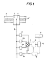
- in stark vereinfachter Darstellungsweise ein Blockschaltschema eines Längenmeßsystems,
- Fig. 2
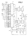
- zur näheren Erläuterung der Funktionsweise eine Korrektureinrichtung mit zwei Teilerschaltungen, einem zugeordneten Umschalter, den Trigger- und Impulsformerstufen und einer Steuereinrichtung für den Umschalter,
- Fig. 3
- in einem Diagramm die Ableitung der digitalen Zählsignale aus den analogen Meßsignalen unter Verwendung der beiden Teilerschaltungen und
- Fig. 4
- in der Fig. 1 entsprechender Darstellungsweise ein Blockschaltschema einer Ausführungsvariante.
- Fig. 1
- in a greatly simplified representation, a block circuit diagram of a length measuring system,
- Fig. 2
- for a more detailed explanation of how it works Correction device with two divider circuits, an assigned changeover switch, the trigger and pulse shaping stages and a control device for the changeover switch,
- Fig. 3
- in a diagram, the derivation of the digital count signals from the analog measurement signals using the two divider circuits and
- Fig. 4
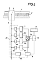
- 1 a block diagram of an embodiment variant.
Nach Fig. 1 besitzt ein vorzugsweise in einem Gehäuse gekapselter Maßstab 1 eine aus Hell-Dunkelfeldern bestehende Meßteilung 2. Entlang des Maßstabes 1 ist über einen Mitnehmer eine Abtasteinheit 3 verstellbar, die durch den Maßstab und gegeneinander um Teilungsbruchteile versetzte Abtastgitter beleuchtete photoelektrische Empfänger aufweist, an deren Ausgängen in ihrer Grundform sinusförmige, gegeneinander phasenverschobene analoge Meßsignale auftreten, wobei im Normalfall am Ausgang 4 zwei um 90° gegeneinander phasenverschobene sinusförmige Meßsignale auftreten, die über nur einpolig dargestellte Leitungen 5 der weiteren Verarbeitung zugeführt werden.According to FIG. 1, a scale 1, preferably encapsulated in a housing, has a measuring
An die Leitungen 5 sind in Parallelschaltung zwei oder mehrere Teilerschaltungen 6, 6a, 6b, 6c angeschlossen. Dabei entspricht die Anzahl n der verwendeten Teilerschaltungen dem Nenner jenes Bruches, der die Größe des Korrekturschrittes im Verhältnis zu einem Zählschritt angibt.Two or
Jede der Teilerschaltungen 6 bis 6c kann über einen elektronischen Umschalter 7, der von einer Steuerlogik 8 gesteuert wird, an eine nachgeordnete Trigger- und Impulsformerstufe 9 angeschaltet werden, wo die aus der jeweils angeschalteten Teilerschaltung 6 bis 6c bei der Verstellung der Abtasteinheit 3 abgetasteten Signale die an der Teilerschaltung entsprechende Triggerpegel ergeben, unter elektronischer Unterteilung der Maßstabteilung in elektronische Zählsignale ausgewertet werden, die einer Verarbeitungseinheit, beispielsweise einer Zähleinrichtung 10 mit nachgeordneter Anzeigeeinrichtung 11 zugeführt werden. Die Teilerschaltungen 6 bis 6c haben untereinander gleiche Teilungsfaktoren, sind aber bezüglich den analogen Meßsignalen hinsichtlich ihrer Triggerpegel um Bruchteile des Teilungsschrittes versetzt, so daß durch Umschaltung des Schalters 7 Korrekturen um diesen Korrekturschritt vorgenommen werden können. Über die Schaltlogik 8 wird hier die Umschaltrichtung des Schalters 7 bestimmt. Ferner kann vorgesehen werden, daß zumindest bei der einen Umschaltrichtung des Schalters die Umschaltung grundsätzlich unmittelbar nach Abgriff des letzten Zählschrittes aus der bisher angeschalteten Teilerschaltung erfolgt, wobei der erste von der neu angeschalteten Teilerschaltung erhaltene Triggerpegel unterdrückt wird, wenn eine sinngemäße Verringerung der Zählschritte durch mehrere Korrekturen erzielt werden soll. Bei dieser Umschaltrichtung würde dann nach einem vollständigen Umlauf des Schalters 7 in der gleichen Richtung über vier Korrekturschritte die Gesamtanzeige um einen Zählschritt weniger anzeigen. Bei umgekehrter Schaltrichtung des Schalters 7 würde über vier Umschaltungen des Schalters 7, wobei die Teilerstufen 6 bis 6c nacheinander angeschaltet werden, ein Zählschritt mehr auftreten als dann, wenn bei Abtastung der gleichen Maßstabstrecke die Stellung des Schalters 7 unverändert bleibt.Each of the
Die Schaltlogik 8 des Schalters 7 kann von einem Speicher und von der Steuereinheit 10 gesteuert werden, so daß durch gezielte Umschaltung in den beiden Verstellrichtungen jede gewünschte Korrekturkurve realisiert werden kann.The switching
Nach Erläuterung des Korrekturprinzips im Zusammenhang mit der Fig. 1 wird nun eine Ausführungsform mit nur zwei Teilerstufen im Zusammenhang mit den Fig. 2 und 3 näher erläutert. Mit dieser Schaltung wird unter Verwendung von Teilerketten 6, 6b ein Korrekturschritt in der Größe eines halben Zählschrittes ermöglicht. Die Teilerstufen 6, 6b sind als Widerstandsteilerketten ausgebildet, wobei die Teilerstufe 6 Triggerpunkte 0/18/36/54/72/90/108/126/144/162 el. Grad und die Teilerkette 6b Triggerpunkte 9/27/45/63/81/99/117/135/153/171 el. Grad bestimmt. Der elektronische Umschalter 7, 7a legt jeweils die eine Teilerkette 6 oder 6b an Triggerstufen 9, 9a, denen je eine Verknüpfungslogik mit Impulsformerstufe 12, 12a (hier gegenüber der Ausführung nach Fig. 1 gesondert gezeichnet) zugeordnet ist. Wird der Analogschalter 7, 7a von der Teilerkette 6 auf die Teilerkette 6b umgestellt, so bedeutet dies, daß, wenn beim Umschaltpunkt 0 el. Grad von 6 auf 6b umgeschaltet wird, der nächste Triggerpunkt nicht bei 18 el. Grad, sondern bei 9 el. Grad, oder wenn durch die Schaltlogik dieser Triggerpunkt unterdrückt wird, bei 27 el. Grad liegt, also ein Korrekturschritt um einen halben Zählschritt ausgeführt wird.After explanation of the correction principle in connection with FIG. 1, an embodiment with only two divider stages in connection with FIGS. 2 and 3 will now be explained in more detail. With this circuit, a correction step the size of half a counting step is made possible using
Die Steuerlogik besitzt eine über eine Umschaltlogik 19 mit den Impulsformerstrufen 12, 12a verbundene, an sich bekannte Impulsvervierfacherschaltung mit Richtungsdiskriminator 13, von dem aus die richtungsabhängigen Zählimpulse einem Vor-Rückwärtszähler 14 zugeführt werden. Im einfachsten Fall bei linearer Korrektur handelt es sich beim Zähler 14 um einen Zähler mit einstellbarem Teilverhältnis. Bei nicht linearer Korrektur ist eine Decoderstufe mit Speicher 15 erforderlich, die entweder über eine hier nicht dargestellte Eingabeeinheit programmiert werden kann oder mit einem vorprogrammierten Festwertspeicher bestückt ist. Die Zähler-Codiereinheit 14, 15 kann auch durch einen Rechner mit Festwertspeicher gebildet werden, in den über eine Eingabeeinheit oder externe Schnittstellen Korrekturpunkte eingegeben werden können. Das am Ausgang der Stufe 14, 15 gewonnene Signal zur Auslösung eines Korrekturschrittes wird in einer Synchronisierstufe 16 so aufbereitet, daß am gewünschten Schaltpunkt (vorzugsweise bei 0 bzw. 9 el. Grad) ein richtungsabhängiger Zählimpuls an einen einen Teil der Schaltlogik 8 bildenden Adresszähler 17 zur Weiterschaltung der Teilerketten über die Analogschalter 7, 7a abgegeben wird.The control logic has a pulse quadruple circuit, known per se, which is connected via a switching
Um Fehlimpulse zu vermeiden, wird man jeden Korrekturschritt einem bestimmten Punkt der periodischen analogen Meßsignale zuordnen und den Korrekturschritt vorzugsweise bei 0 el. Grad vornehmen. Diese Synchronisierung erfolgt in der Synchronisierstufe 16, die einen Zählschritt für den Adresszähler 17 nur dann auslöst, wenn die genannte Bedingung erfüllt ist. Eine Freigabelogik 18 bewirkt, daß am Umschaltpunkt bei 0 bzw. 9 el. Grad die eigene Teilerstufe 6 bzw. 6b erst dann geschaltet wird, wenn der Triggerpunkt der benachbarten Stufe erreicht ist. Es wird dadurch zu diesem Zeitpunkt eine neuerliche Umschaltung über den Triggerausgang und die Erzeugung eines Fehlimpulses vermieden.In order to avoid false impulses, each correction step will be assigned to a specific point of the periodic analog measurement signals and the correction step is preferably carried out at 0 degrees. This synchronization takes place in the
Die schon erwähnte Umschaltlogik 19 hat den Zweck, mit einfachen Mitteln aufeinanderfolgende gleichsinnige Korrekturen zu ermöglichen, also nach Vornahme von einem vollen Zählschritt entsprechenden Korrekturschritten, die Weiterverarbeitung der Signale störungsfrei zu gewährleisten. Theoretisch könnten zur Lösung dieser Aufgabe die Analogschalter 7, 7a jeweils nach Erreichen einer Korrektur um einen ganzen Zählschritt um eine volle Stufe weiterschalten, also z. B. den bisher mit dem Triggerpunkt 0 bzw. 9 verbundenen Schalterteil auf den Triggerpunkt 36, 45 umschalten usw. Über die Umschaltlogik 19 läßt sich die gleiche Aufgabe mit einfacheren Mitteln in dem digitalen Teil der Schaltung lösen. Die Umschaltlogik 19 wird zu diesem Zweck vom Adresszähler 17 gesteuert und wechselt entsprechend den Steuersignalen die Verbindung der Impulsformerstufen 12, 12a mit den zur weiteren Verarbeitung führenden Ausgängen.The switching
In Fig. 3 sind zur Verdeutlichung der Wirkungsweise der erfindungsgemäßen Schaltung die an den Leitungen 5 auftretenden Analogsignale und die Ableitung der Zählsignale T1, T2, T1', T2', aus dem Abgriff der Teilerketten bei Anschaltung der beiden Teilerketten 6 bzw. 6b veranschaulicht.In Fig. 3 are to illustrate the operation of the invention Circuit illustrates the analog signals occurring on the
Eine Vereinfachung der Schaltung wäre zumindest theoretisch dann möglich, wenn über die Abtasteinheit 3 oder eine der Abtasteinheit nachgeordnete Umformerstufe für die analogen Meßsignale genau dreieckförmige Analogsignale erhalten werden. Hier könnte mit nur einer Teilerkette gearbeitet werden, bei der zur Phasenverschiebung der Teilerpunkte Widerstände über den Schalter 7 vor- bzw. nachgeschaltet werden.A simplification of the circuit would be possible at least theoretically if exactly triangular analog signals are obtained for the analog measuring signals via the
Besonders, wenn die Schaltung 14, 15 aus einem Rechner gebildet wird, kann man zum Ausgleich äußerer Parameter und eines dadurch bedingten linearen Fehlers, z. B. des Wärmedehnungsfehlers Temperaturfühler vorsehen, die entsprechende Korrekturen durch periodische Umschaltung des Schalters 7, 7a bewirken.Especially when the
Die Ausführung nach Fig. 4 unterscheidet sich von der Ausbildung nach Fig. 1 dadurch, daß jeder Teilerschaltung 6 bis 6c auch eine Trigger- und Impulsformerstufe 9 bis 9c zugeordnet ist, an deren Ausgang an sich bereits digitale Zählsignale auftreten, die aber wieder bezüglich des Grundsignales um Zählschrittbruchteile versetzt sind. Der Wählschalter 7b wird wieder von der Steuerlogik 8 gesteuert und ist entweder über eine eigene, an der Leitung 5 liegende Synchronisierstufe 20 oder, wie strichpunktiert über die Leitung 21 angedeutet, durch Verbindung mit dem Ausgang der einen Teilerkette auf die analogen Meßsignale synchronisiert.The embodiment according to FIG. 4 differs from the embodiment according to FIG. 1 in that each
Die erfindungsgemäße Korrektureinrichtung ist zwar vorwiegend für Längenmeßsysteme bestimmt, kann aber sogar bei Winkelmeßsystemen oder Drehmeldern eingesetzt werden, bei denen bisher eine feinstufige mechanische Korrektur überhaupt unmöglich war und Korrekturen im Bedarfsfall nur durch Hinzufügen oder Unterdrücken von Zählschritten vorgenommen wurden.The correction device according to the invention is primarily intended for length measuring systems, but can even be used in angle measuring systems or resolvers in which a fine-tuned mechanical correction has so far been used was impossible and corrections were only made if necessary by adding or suppressing counting steps.
Claims (9)
- A method of electronic correction of position errors in an incremental measuring system, more particularly an incremental length-measuring system, in which periodic, basically sinusoidal analog measuring signals are generating by scanning a measuring graduation (2) by means of a scanning unit (3) and are used in a divider stage (6), with electronic subdivision of the scale, to derive digital counting signals (T₁, T₂), dependent on the direction of adjustment, for an evaluating device (10, 11), each counting signal being associated with a particular phase position of the measuring signals, characterised in that for the purpose of error correction, additional signal levels offset by defined fractions of the graduation step are determined between the signal levels associated with the counting signals (T₁, T₂) and spaced apart in phase with the subdivision places, and the evaluation of the measurement is optionally related to the offset signal levels in accordance with a corrective program, so that corrections can be made in steps corresponding just to fractions of the graduation step.
- An incremental measuring system in which periodic, basically sinusoidal analog measuring signals generated by scanning a measuring graduation (2) by means of a scanning unit (3) are supplied to a divider circuit (6) and used via trigger and pulse-shaping stages (9, 12) with electronic subdivision of the measuring graduation (2) of the scale (1) to derive digital counting signals (T₁, T₂), dependent on the direction of adjustment, for an evaluating circuit (10, 11), e.g. a display or control circuit, electronic error correction means being provided, characterised in that for the purpose of error correction, two or more divider circuits (6 - 6c) are provided with the same subdivision factor but with trigger level positions which are phase-shifted from one another by fractions of the graduation step relative to the analog measuring signal, and each circuit can be connected to the evaluating circuit (10) via an electronic selector switch (7, 7a, 7b) controlled in accordance with a correction program.
- A length-measuring system according to claim 2, characterised in that the selector switch (7, 7a) is provided between the divider circuits (6 - 6c) and the common trigger and pulse-shaping stages (9, 12) associated with the evaluating circuit (10).
- A length-measuring system according to claim 2, characterised in that each divider circuit (6 - 6c) is associated with a separate trigger and/or pulse-shaping stage (9 - 9c) and the selector switch (7b) is a digital change-over switch downstream of the pulse-shaping stages.
- A length-measuring system according to any of claims 2 to 4, characterised in that the selector switch (7, 7a, 7b) is synchronised with a preset level of at least one analog measuring signal, preferably with the passage thereof through zero.
- A length-measuring system according to any of claims 2 to 5, characterised in that the selector switch (7, 7a, 7b) is provided with a control logic (8; 14 to 19; 20) which does not allow the selector switch to change over until a counting signal has been tapped from the instantaneously connected divider circuit (6 to 6c).
- A length-measuring system according to any of claims 2 to 6, characterised in that the electronic selector switch (7, 7a) is controlled by an adjustable counter (14, 15) which is supplied with the counting signals and which generates a change-over command for the selector switch (7, 7a) whenever the set counter level is reached.
- A length-measuring system according to claim 7, characterised in that the counter (14, 15) is adjustable in dependence on the ambient temperature detected by a temperature monitor.
- A length-measuring system according to any of claims 2 to 8, characterised in that a correction memory (15) for controlling the selector switch (7, 7a, 7b) is provided and contains addresses which can be interrogated in dependence on the position of the scanning unit (3) on the scale (1).
Applications Claiming Priority (2)
| Application Number | Priority Date | Filing Date | Title |
|---|---|---|---|
| AT716/89A AT393029B (en) | 1989-03-29 | 1989-03-29 | INCREMENTAL LENGTH MEASURING SYSTEM |
| AT716/89 | 1989-03-29 |
Publications (2)
| Publication Number | Publication Date |
|---|---|
| EP0390770A1 EP0390770A1 (en) | 1990-10-03 |
| EP0390770B1 true EP0390770B1 (en) | 1993-08-04 |
Family
ID=3497926
Family Applications (1)
| Application Number | Title | Priority Date | Filing Date |
|---|---|---|---|
| EP90890081A Expired - Lifetime EP0390770B1 (en) | 1989-03-29 | 1990-03-21 | Method for the electronic correction of position error in an incremental measuring system and measuring system for implementation of the method |
Country Status (4)
| Country | Link |
|---|---|
| US (1) | US5021650A (en) |
| EP (1) | EP0390770B1 (en) |
| AT (1) | AT393029B (en) |
| DE (1) | DE59002145D1 (en) |
Cited By (1)
| Publication number | Priority date | Publication date | Assignee | Title |
|---|---|---|---|---|
| DE102004041391A1 (en) * | 2004-08-26 | 2006-03-02 | Jungheinrich Aktiengesellschaft | Measuring device for the incremental measurement of positions, travel ranges or angles and equipped with such a measuring device truck |
Families Citing this family (15)
| Publication number | Priority date | Publication date | Assignee | Title |
|---|---|---|---|---|
| DE69126938T2 (en) * | 1990-10-11 | 1998-02-12 | Canon Kk | Positioning device |
| US5572019A (en) * | 1991-03-12 | 1996-11-05 | Canon Kabushiki Kaisha | Encoder with varying width light receiver and apparatus having the encoder |
| IT1279641B1 (en) | 1995-10-03 | 1997-12-16 | Marposs Spa | APPARATUS FOR CHECKING THE DIAMETER OF CONNECTING ROD PINS IN ORBITAL MOTION |
| IT1321212B1 (en) * | 2000-03-06 | 2003-12-31 | Marposs Spa | PIN DIAMETER CONTROL EQUIPMENT. |
| US6396052B1 (en) | 2000-04-07 | 2002-05-28 | Lexmark International, Inc. | High precision analog encoder system |
| DE102005036161A1 (en) * | 2005-08-02 | 2007-02-08 | Dr. Johannes Heidenhain Gmbh | Field modulating angle measuring device and method for its operation |
| JP5112989B2 (en) * | 2008-08-20 | 2013-01-09 | 株式会社ミツトヨ | Photoelectric encoder |
| JP5149820B2 (en) * | 2009-01-19 | 2013-02-20 | キヤノン株式会社 | Controller and processing equipment |
| DE102009032353A1 (en) | 2009-07-08 | 2011-09-08 | Hommel-Etamic Gmbh | Method for determining the shape of a workpiece |
| DE102009042252B4 (en) | 2009-09-22 | 2014-03-06 | Jenoptik Industrial Metrology Germany Gmbh | measuring device |
| JP5641746B2 (en) * | 2010-02-12 | 2014-12-17 | 株式会社ミツトヨ | Photoelectric encoder |
| DE102010013069B4 (en) * | 2010-03-26 | 2012-12-06 | Hommel-Etamic Gmbh | measuring device |
| DE102010035147B4 (en) | 2010-08-23 | 2016-07-28 | Jenoptik Industrial Metrology Germany Gmbh | measuring device |
| DE102012018580B4 (en) | 2012-09-20 | 2015-06-11 | Jenoptik Industrial Metrology Germany Gmbh | Measuring device and measuring method for in-process measurement on test specimens during a machining operation on a processing machine, in particular a grinding machine |
| EP2908098B1 (en) * | 2014-02-18 | 2016-11-30 | Hexagon Technology Center GmbH | Linear encoder with calibrating functionality |
Family Cites Families (10)
| Publication number | Priority date | Publication date | Assignee | Title |
|---|---|---|---|---|
| US2336550A (en) * | 1943-05-01 | 1943-12-14 | Fisher Scientific Co | Compensating spectrophotometer |
| US2985826A (en) * | 1959-11-19 | 1961-05-23 | Phillips Petroleum Co | Electrical measuring apparatus |
| US3039032A (en) * | 1960-03-30 | 1962-06-12 | Andrew H Fowler | Error compensator for a position transducer |
| US3182385A (en) * | 1963-03-29 | 1965-05-11 | Esposito Frank | Alternator field rotor separating tool |
| US3713139A (en) * | 1971-01-25 | 1973-01-23 | Bendix Corp | Apparatus and method of determining displacements |
| DE2942080C2 (en) * | 1979-10-18 | 1982-12-02 | Hottinger Baldwin Messtechnik Gmbh, 6100 Darmstadt | Method and circuit arrangement for the digital measurement of incrementally subdivided paths or angles of rotation |
| US4445110A (en) * | 1980-07-28 | 1984-04-24 | Itek Corporation | Absolute optical encoder system |
| DE3208591C2 (en) * | 1982-03-10 | 1986-06-05 | Dr. Johannes Heidenhain Gmbh, 8225 Traunreut | Digital electrical length or angle measuring system |
| US4680466A (en) * | 1984-04-20 | 1987-07-14 | Yokogawa Hokushin Electric Corporation | Displacement transducer which simultaneously extracts signals via sequential switching |
| DE3416091A1 (en) * | 1984-04-30 | 1985-10-31 | Siemens AG, 1000 Berlin und 8000 München | Device for scale correction in a numerically controlled machine tool |
-
1989
- 1989-03-29 AT AT716/89A patent/AT393029B/en not_active IP Right Cessation
-
1990
- 1990-03-21 DE DE9090890081T patent/DE59002145D1/en not_active Expired - Fee Related
- 1990-03-21 EP EP90890081A patent/EP0390770B1/en not_active Expired - Lifetime
- 1990-03-28 US US07/500,800 patent/US5021650A/en not_active Expired - Fee Related
Cited By (1)
| Publication number | Priority date | Publication date | Assignee | Title |
|---|---|---|---|---|
| DE102004041391A1 (en) * | 2004-08-26 | 2006-03-02 | Jungheinrich Aktiengesellschaft | Measuring device for the incremental measurement of positions, travel ranges or angles and equipped with such a measuring device truck |
Also Published As
| Publication number | Publication date |
|---|---|
| AT393029B (en) | 1991-07-25 |
| DE59002145D1 (en) | 1993-09-09 |
| US5021650A (en) | 1991-06-04 |
| EP0390770A1 (en) | 1990-10-03 |
| ATA71689A (en) | 1990-12-15 |
Similar Documents
| Publication | Publication Date | Title |
|---|---|---|
| EP0390770B1 (en) | Method for the electronic correction of position error in an incremental measuring system and measuring system for implementation of the method | |
| DE4215798C2 (en) | Warp knitting machine | |
| DE2724602C3 (en) | Device for synchronizing a gear processing machine | |
| DE69717245T2 (en) | Procedure for changing interpolation factors | |
| DE3900270A1 (en) | DEVICE FOR POSITION DETECTION | |
| DE2422104C3 (en) | Device to compensate for the grinding wheel shrinkage that occurs when dressing a grinding wheel | |
| DE3306325C2 (en) | ||
| EP0062698B1 (en) | Evaluation circuit for a digital rotational speed transducer | |
| DE3202356C1 (en) | Device for dividing periodic analog signals | |
| DE1548692A1 (en) | Method and arrangement for interpolating | |
| DE3788329T2 (en) | Device for displaying the value of a variable. | |
| CH669354A5 (en) | ||
| EP0399989B1 (en) | Incremental measuring system | |
| EP0291763B1 (en) | Control system for a cutter | |
| DE3742329C1 (en) | Position measuring device with subdivision circuit | |
| EP0517690B1 (en) | Incremental measuring system | |
| EP0298183B1 (en) | Incremental position measuring system | |
| DE2332981C3 (en) | Circuit for generating a voltage proportional to the phase shift of two pulse trains | |
| DE2400285C2 (en) | Evaluation device for frequency or period duration analog measurement signals | |
| DE4120861C2 (en) | Travel measuring device | |
| DE10060185B4 (en) | Device and method for measuring angles | |
| CH673487A5 (en) | ||
| AT404191B (en) | Measurement system | |
| EP0500860B1 (en) | Method of measuring lengths | |
| DE1163436B (en) | Method and device for the automatic adjustment of a machine part |
Legal Events
| Date | Code | Title | Description |
|---|---|---|---|
| PUAI | Public reference made under article 153(3) epc to a published international application that has entered the european phase |
Free format text: ORIGINAL CODE: 0009012 |
|
| AK | Designated contracting states |
Kind code of ref document: A1 Designated state(s): BE CH DE FR GB IT LI LU NL SE |
|
| 17P | Request for examination filed |
Effective date: 19900925 |
|
| 17Q | First examination report despatched |
Effective date: 19921130 |
|
| GRAA | (expected) grant |
Free format text: ORIGINAL CODE: 0009210 |
|
| AK | Designated contracting states |
Kind code of ref document: B1 Designated state(s): BE CH DE FR GB IT LI LU NL SE |
|
| REF | Corresponds to: |
Ref document number: 59002145 Country of ref document: DE Date of ref document: 19930909 |
|
| ET | Fr: translation filed | ||
| ITF | It: translation for a ep patent filed | ||
| GBT | Gb: translation of ep patent filed (gb section 77(6)(a)/1977) |
Effective date: 19930927 |
|
| PGFP | Annual fee paid to national office [announced via postgrant information from national office to epo] |
Ref country code: SE Payment date: 19940310 Year of fee payment: 5 |
|
| PGFP | Annual fee paid to national office [announced via postgrant information from national office to epo] |
Ref country code: NL Payment date: 19940331 Year of fee payment: 5 Ref country code: LU Payment date: 19940331 Year of fee payment: 5 Ref country code: BE Payment date: 19940331 Year of fee payment: 5 |
|
| EPTA | Lu: last paid annual fee | ||
| PLBE | No opposition filed within time limit |
Free format text: ORIGINAL CODE: 0009261 |
|
| STAA | Information on the status of an ep patent application or granted ep patent |
Free format text: STATUS: NO OPPOSITION FILED WITHIN TIME LIMIT |
|
| 26N | No opposition filed | ||
| EAL | Se: european patent in force in sweden |
Ref document number: 90890081.4 |
|
| PG25 | Lapsed in a contracting state [announced via postgrant information from national office to epo] |
Ref country code: LU Free format text: LAPSE BECAUSE OF NON-PAYMENT OF DUE FEES Effective date: 19950321 |
|
| PG25 | Lapsed in a contracting state [announced via postgrant information from national office to epo] |
Ref country code: SE Effective date: 19950322 |
|
| PG25 | Lapsed in a contracting state [announced via postgrant information from national office to epo] |
Ref country code: BE Effective date: 19950331 |
|
| BERE | Be: lapsed |
Owner name: RSF-ELEKTRONIK G.M.B.H. Effective date: 19950331 |
|
| PG25 | Lapsed in a contracting state [announced via postgrant information from national office to epo] |
Ref country code: NL Effective date: 19951001 |
|
| NLV4 | Nl: lapsed or anulled due to non-payment of the annual fee |
Effective date: 19951001 |
|
| EUG | Se: european patent has lapsed |
Ref document number: 90890081.4 |
|
| PGFP | Annual fee paid to national office [announced via postgrant information from national office to epo] |
Ref country code: GB Payment date: 19980213 Year of fee payment: 9 Ref country code: FR Payment date: 19980213 Year of fee payment: 9 |
|
| PGFP | Annual fee paid to national office [announced via postgrant information from national office to epo] |
Ref country code: CH Payment date: 19980225 Year of fee payment: 9 |
|
| PG25 | Lapsed in a contracting state [announced via postgrant information from national office to epo] |
Ref country code: GB Free format text: LAPSE BECAUSE OF NON-PAYMENT OF DUE FEES Effective date: 19990321 |
|
| PG25 | Lapsed in a contracting state [announced via postgrant information from national office to epo] |
Ref country code: LI Free format text: LAPSE BECAUSE OF NON-PAYMENT OF DUE FEES Effective date: 19990331 Ref country code: CH Free format text: LAPSE BECAUSE OF NON-PAYMENT OF DUE FEES Effective date: 19990331 |
|
| GBPC | Gb: european patent ceased through non-payment of renewal fee |
Effective date: 19990321 |
|
| REG | Reference to a national code |
Ref country code: CH Ref legal event code: PL |
|
| PG25 | Lapsed in a contracting state [announced via postgrant information from national office to epo] |
Ref country code: FR Free format text: LAPSE BECAUSE OF NON-PAYMENT OF DUE FEES Effective date: 19991130 |
|
| REG | Reference to a national code |
Ref country code: FR Ref legal event code: ST |
|
| PG25 | Lapsed in a contracting state [announced via postgrant information from national office to epo] |
Ref country code: IT Free format text: LAPSE BECAUSE OF NON-PAYMENT OF DUE FEES;WARNING: LAPSES OF ITALIAN PATENTS WITH EFFECTIVE DATE BEFORE 2007 MAY HAVE OCCURRED AT ANY TIME BEFORE 2007. THE CORRECT EFFECTIVE DATE MAY BE DIFFERENT FROM THE ONE RECORDED. Effective date: 20050321 |
|
| PGFP | Annual fee paid to national office [announced via postgrant information from national office to epo] |
Ref country code: DE Payment date: 20060314 Year of fee payment: 17 |
|
| PG25 | Lapsed in a contracting state [announced via postgrant information from national office to epo] |
Ref country code: DE Free format text: LAPSE BECAUSE OF NON-PAYMENT OF DUE FEES Effective date: 20071002 |