EP0388346A2 - Auf Berührung reagierendes Bildschirmgerät - Google Patents
Auf Berührung reagierendes Bildschirmgerät Download PDFInfo
- Publication number
- EP0388346A2 EP0388346A2 EP90480041A EP90480041A EP0388346A2 EP 0388346 A2 EP0388346 A2 EP 0388346A2 EP 90480041 A EP90480041 A EP 90480041A EP 90480041 A EP90480041 A EP 90480041A EP 0388346 A2 EP0388346 A2 EP 0388346A2
- Authority
- EP
- European Patent Office
- Prior art keywords
- display
- springs
- spring
- display screen
- crt
- Prior art date
- Legal status (The legal status is an assumption and is not a legal conclusion. Google has not performed a legal analysis and makes no representation as to the accuracy of the status listed.)
- Granted
Links
Images


Classifications
-
- G—PHYSICS
- G06—COMPUTING; CALCULATING OR COUNTING
- G06F—ELECTRIC DIGITAL DATA PROCESSING
- G06F3/00—Input arrangements for transferring data to be processed into a form capable of being handled by the computer; Output arrangements for transferring data from processing unit to output unit, e.g. interface arrangements
- G06F3/01—Input arrangements or combined input and output arrangements for interaction between user and computer
- G06F3/03—Arrangements for converting the position or the displacement of a member into a coded form
- G06F3/041—Digitisers, e.g. for touch screens or touch pads, characterised by the transducing means
- G06F3/0414—Digitisers, e.g. for touch screens or touch pads, characterised by the transducing means using force sensing means to determine a position
- G06F3/04142—Digitisers, e.g. for touch screens or touch pads, characterised by the transducing means using force sensing means to determine a position the force sensing means being located peripherally, e.g. disposed at the corners or at the side of a touch sensing plate
Definitions
- This invention relates to position indicating data input touch systems and position dependent force measuring systems such as are employed in touch sensitive tablet and position locating systems in general, and relates specifically to a touch sensing display screen apparatus of the type generally known as a "touchscreen”.
- US Patent 4,340,777 to DeCosta et al discloses a unique mounting and force application system for providing moment-free unidirectional force to sensors utilized in a touch input device as well as methods of sampling various sensors and determining when threshold levels of touch discrimination have been reached.
- US Patent 4,355,202 to DeCosta et al shows various applications of the moment-free force input sensor structure of US Patent 4,340,777 in a system which directly employs a CRT or other data display apparatus as the touch tablet or screen.
- Yet another object of the present invention is to provide an improved touch input display system of simple and robust structure which does not require extensive additional elements or parallax-inducing, vision-obstructing elements or panels.
- any desired electro-optical display such as a cathode ray tube (CRT), a cold plasma display screen, a liquid crystal display (LCD), light emitting diode displays (LEDs), electroluminescent panels, incandescent or neon bulb panels or any similar "electro-optic" display device is supported directly upon a plurality of beam springs.
- the beam springs are preferably double cantilever mounted to provide essentially only a single degree of freedom in bending in a plane perpendicular to the long axis of the beam.
- each leaf spring is rigidly affixed to a mounting point serving as mechanical ground in the frame or housing of the display device and the other end of each spring is rigidly affixed to the display screen itself or to a frame which is affixed to the display screen itself.
- the springs thereby provide the sole physical support for the mass of the display screen.
- the dimensions of each leaf spring are chosen so as to provide for deflection in essentially a single axis of bending that is arranged to lie along an axis generally perpendicular to to the surface of the display screen itself.
- a CRT is supported at its four corners by the cantilever mounted beam springs which bear the entire weight of the CRT display. Forces imposed by touching the surface of the CRT are measured by strain gauges affixed to the flat surfaces of the beam springs which are stressed in response to forces applied to the surface of the CRT display.
- High output sensitivity is maintained despite the very small deflections of the system by providing high sensitivity foil or semiconductive strain gauges bonded securely to the supporting springs in the assembly.
- the springs themselves are preferably flat leaf or beam springs mounted in double cantilever fashion, i.e. both ends securely mounted and clamped to provide bending stresses only in responses to deflections of the supported element.
- the strain gauges are placed relative to the inflection of an S-shaped bend in the spring to put some gauges in tension and some others in compression. By appropriate placement and connection of the gauges into a Wheatstone bridge measurement circuit, high electrical output may be obtained from very small physical strains imposed in the cantilever springs.
- the springs may be made relatively wide in the axis transverse to the bending axis so that side deflec tions or loads imposed upon the supported display screen are strongly resisted and little or no deflection occurs in any axis other than the axis generally perpendicular to the surface of the display screen. This is a uniaxial freedom of movement or unidirectional freedom of movement supporting system. Removing the strain gauges or force sensing elements from the role of having to directly support the mass and weight of the screen or touch tablet greatly alleviates the potential of damages from stresses applied to these sensitive elements.
- FIG. 1 an exploded view of the major components of a touch sensitive input display screen apparatus according to the preferred embodiment of the invention is shown.
- a CRT 1 is chosen as the representative electro-optical display screen or device, but it will be understood that any electro-optical display device such as LCDs, LEDs, electroluminescent display, flat panel plasma displays or even incandescent or fluorescent displays, gas discharge displays or any of the like are generally encompassed by the term "electro-optical” display.
- CRTs are the most commonly employed electro-optical devices today, particularly in applications involving the use of interactive user application programs on computer systems. Consequently, the preferred embodiment is illustrated utilizing a CRT that will be employed with a computer system monitor display.
- the CRT 1 is normally supplied with a stout metal band 2 incorporating mounting tabs or ears 3 with which the CRT is normally firmly affixed inside a bezel 4 or to a mounting framework in the chassis of a CRT display monitor and/or its housing (not shown).
- each beam spring 5 is tightly affixed to clamping plate or mounting surface elements 6 in the bezel 4.
- the springs 5 are thus cantilever mounted and are rigidly held by the mounting element 6 at one end of each spring 5.
- the other end of each spring 5 is connected either directly to the mounting tab or ears 3, or to an intermediate adjustable clamp 7 which permits adjustment relative to the springs 5.
- This adjustment permits the display 1 to be oriented with its surface coplanar to the front of the bezel 4 and to account for any slight mechanical construction variance tolerances in the placement of the locating ears or mounting tabs 3, the mounting plate 6 and the spring elements 5.
- each end of each spring 5 is thus rigidly clamped in a supporting structure upon assembly.
- flexure of the beam springs 5 mounted in their cantilever fashion is primarily limited to the Z axis direction. Flexure is in response to any forces applied in the XY plane on the surface of the CRT 1.
- Flexible cables 8 are terminated in a connector 9 which may be supplied, optionally, with a cable 10 for connection remotely to another connector 11 mounted on an electrical calculator processor card 12 that carries out the X,Y and Z resultant force locus calculations and total force summations from the signals supplied to it.
- the processor or calculation card may preferably be a microprocessor of a commercially available type such as the Intel Corporation's 80C196 Microcontroller which advantageously incorporates a 10 bit A to D converter on it together with other appropriate circuitry as will be described in greater detail later.
- Strain gauges 13 are mounted on each spring 5 and connected via cable 8 and connector 9/11 to the calculating processor card 12 for supplying the electrical input signals thereto.
- the strain gauges 13 are connected in a full four-way Wheatstone bridge at each spring 5, i.e. four individual strain gauges may be employed on each spring 5 as will be described in greater detail later.
- the X, Y and Z calculating microprocessor 12 supplies its output in the form of electrical signals representing the locus of the application of force to the surface of the screen of the display device 1 and the magnitude of the force in the Z axis. These outputs are clocked at high speed to provide signals essentially continuously via output cable 14 to the input port 15 of the system computer 16.
- There the XY position data and the Z axis total force information from the processor 12 may be utilized in a variety of interactive application programs as is apparent to those of skill in this art.
- the applications for the X, Y and Z input data resulting from the output of the calculating processor 12 are amply described in the aforementioned patents listed under the prior art section hereof and need no further description to those of skill in this field.
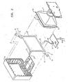
- FIG 2 an exploded view of a somewhat more detailed form of an alternative embodiment of the preferred invention mechanical structure is shown.
- This alternative embodiment incorporates a rigid separate frame 17.
- Frame 17 incorporates the spring mounting and clamping arrangement for one end of each spring 5 as shown by element 7 which, in this case is integrally made with frame 17.
- the frame 17 is attached to the mounting ears or lugs 3 which are part of the CRT 1's usual mechanical support elements as previously noted.
- the other elements are similarly numbered to those same elements as shown in Figure 1 and are not discussed further with respect to this drawing.
- Figure 3 comprising Figures 3A through 3D, a more detailed explanation of the use of the double cantilever mounted beam spring elements 5 depicted in Figures 1 and 2 will be given.
- FIG 3A a plan view of a generally flat leaf spring 5 is shown.
- Leaf spring 5 in the preferred embodiment may be formed of heat treated 17-7 PH stainless steel having approximately 190,000 psi minimum yield strength.
- the typical dimensions found advantageous in a preferred embodiment for leaf spring 5 are length L of .972 inches, a width W of .550 inches and a thickness T of .032 inches.
- Mounting holes 18 are drilled, stamped or etched in each end of the spring 5 as shown in Figure 3A and four strain gauges 13-1 through 13-4 are firmly bonded with the usual strain gauge bonding agent to the surface of spring 5.
- the gauges are roughly equidistant from the center line/inflection point of bending as shown by the dotted line through the center of spring 5 in its depictions in Figures 3A through 3D.
- the strain gauges 13-1 through 13-4 are the commercially available constantan foil type gauges having a gauge factor Gf of approximately and a nominal resistance of 1200 ohms, where E is the unit of strain and R is resistance in ohms. As implemented on the springs in the preferred embodiment, these gauges yield approximately a millivolt per pound of force as a signal output with a 10 volt DC input when implemented in a full four way Wheatstone bridge.
- Figure 3B illustrates the horizontal cross section of beam spring 5 and the placement of the strain gauges 13 on its surface.
- Figure 3C illustrates a beam spring 5 mounted in double cantilever fashion between mounts 6 and 7 and under strain imposed by finger pressure applied to a display surface 1 so that spring 5 is deflected in bending into an approximate capital S shape.
- This has been shown highly exaggerated in Figure 3C in order to illustrate the fact that gauges 13-1 and 13-2 will be placed in tension while gauges 13-3 and 13-4 will be placed in compression.
- Gauges 13-1 and 13-2 will be connected in diagonally opposite legs of the full Wheatstone bridge arrangement and gauges 13-3 and 13-4 are connected in the other two diagonally opposed legs as will be well understood by those of skill in the art. Utilizing four strain gauges with two being in compression and two being in extension provides twice the electrical output signal as would be provided by a single pair of gauges.
- Figure 3D is the resultant stress diagram of the spring 5 when it is cantilever mounted as shown. It clarifies the point that two of the gauges are located so as to experience tensile strain while those of its compliment experience compressive strain.
- springs 5 yield a stiffness of 4,181 pounds per inch for each spring 5 when mounted as shown.
- the total stiffness is 16,724 pounds of force per inch of deflection, approximately, when a rigid frame is utilized to eliminate torsional moments at the end of springs 5 adjacent to the CRT 1.
- a force of four pounds will produce a deflection of approximately two ten thousandths of an inch.
- the CRT 1 is solely supported by its integral band 2 and mounting lugs 3 to a rigid framework 17 which has integrally made into it the mounting clamp 7 for one end of each spring 5.
- a screw or other suitable fastening means 19 secures the mounting lug 3 to the framework 17 that substantially eliminates any torsional moments from being applied to spring 5.
- a rigid mounting clamp comprising element 7 and screw 20 with a washer or a spacer 21 is also employed.
- Clamp 6 comprises a screw 22 and washers or clamp members 23 as shown. Strain gauges 13 are shown without the electrical connecting leads which are well known in the art.
- the housing or bezel 4 for the CRT is seen not to actually be in physical contact with the CRT 1. Hence it will be observed that the entire weight or mass of the cathode ray tube 1 (or any equivalent electro-optical display device) is, in accordance with the present invention, fully floatingly supported by the beam springs 5.
- springs 5 are configured to exhibit essentially only a single degree of freedom in bending.
- the lateral width of each spring 5 is chosen to be relatively great as compared to its thickness to resist any substantial transverse axial forces either horizontally or longitudinally.
- spring 5 is essentially free to bend only in the axis perpendicular to its own longitudinal axis and parallel with the Z axis of orientation of the display screen 1.
- a theoretical natural resonant frequency of the free floating CRT, beam spring and end mounting arrangement is approximately 100 hz.
- the natural resonant frequency drops to approximately 10 hz due to the inherent flexibility of the plastic or metal bezel which allows some slight torsional and bending moment at the end where clamp 6 connects the bezel 4 to the spring 5.
- the torsional moment is primarily due to the flexing of the bezel 4 as will be apparent to those of skill in the art.
- the bezel 4 may be made of cast metal and made very stiff so that the theoretical resonant frequency of the assembly remains higher.
- the suitable range of stiffness for springs 5 thus lies in the range of approximately 40 to 40,000 pounds per inch and conservatively in the range of 100 to 10,000 pounds per inch compliance.
- Figure 5 illustrates in some detail an enlarged corner section of an alternative mounting arrangement for the CRT display 1 within the bezel 4 utilizing the spring elements 5 as previously noted.
- the stiff framework 17 has integral clamp portion 7 similar to those described with respect to Figure 4.
- the screw element 19 which fastens the mounting ears 3 of the CRT to the frame 17 is outfitted with an adjusting nut so that the Z axis placement of the CRT 1 relative to the frame 17 may be slightly adjusted to account for any manufacturing tolerances or errors in the placement of the support clamps 6, the length of springs 5, mechanical differences in the thickness or dimension of clamps 7 and frame 17 or of the mounting lugs 3 and band 2 on the surface of the CRT 1.
- This enables alignment of the CRT 1 along the Z axis with equal load applied to all springs 5 when forces are imposed on the center of the display 1.
- Elements not specifically discussed herein are similarly numbered to those appearing in Figures 1 through 4 and are thus not discussed further.
- the preferred embodiment of the invention is realized commercially in an embodiment utilizing a computer monitor-CRT as a user interactive touch surface input device.
- the surface of the CRT is directly touched and pushed by a human user to indicate selection of a displayed element on the face of the display.
- the forces imposed on the system due to the human touch on the CRT are monitored at each corner of the display via the sole support elements, the relatively thin beam springs 5 with appropriately mounted strain sensing elements 13 as discussed.
- the beam springs 5 are attached via clamping arrangements 6 and 7 at each end to provide cantilever mounting for the beams.
- the beam springs 5 are designed to deflect only slightly or, to a human, imperceptibly when a force is applied to the screen of the display device.
- the beam spring material and physical dimensions as described herein are optimized to provide both adequate deflection to provide adequate signals under low touch input forces in the range of one pound while still providing adequate material fatigue and impact strength to withstand millions of flexures and to resist the stresses imposed by shipment, intentional attempts at overstress by vandals, and the like.
- Heat treatable steel is preferred for the springs 5 since such materials exhibit a relatively constant elastic modulus that is needed for providing transducer linearity and consequent signal linearity in the output from the strain gauges.
- the width and thickness of each beam spring are also advantageously optimized to decrease force sensitivity in the X or Y directions and to provide a strong and secure mounting of the CRT or display screen within its chassis or bezel.
- Allowing the CRT or display device to be floatingly mounted on the beam springs 5 alone does increase the vibration susceptibility of the system since the mass of the CRT is relatively high. It follows that stiff springs must be employed in order to keep excursions in the Z axis low (and the natural resonant frequency high) in response to vibration forces and accelerations commonly present in today's environment.
Applications Claiming Priority (2)
| Application Number | Priority Date | Filing Date | Title |
|---|---|---|---|
| US324777 | 1989-03-14 | ||
| US07/324,777 US5038142A (en) | 1989-03-14 | 1989-03-14 | Touch sensing display screen apparatus |
Publications (3)
| Publication Number | Publication Date |
|---|---|
| EP0388346A2 true EP0388346A2 (de) | 1990-09-19 |
| EP0388346A3 EP0388346A3 (de) | 1991-04-10 |
| EP0388346B1 EP0388346B1 (de) | 1997-11-12 |
Family
ID=23265068
Family Applications (1)
| Application Number | Title | Priority Date | Filing Date |
|---|---|---|---|
| EP90480041A Expired - Lifetime EP0388346B1 (de) | 1989-03-14 | 1990-03-13 | Auf Berührung reagierendes Bildschirmgerät |
Country Status (4)
| Country | Link |
|---|---|
| US (1) | US5038142A (de) |
| EP (1) | EP0388346B1 (de) |
| JP (1) | JPH02275522A (de) |
| DE (1) | DE69031691T2 (de) |
Cited By (8)
| Publication number | Priority date | Publication date | Assignee | Title |
|---|---|---|---|---|
| EP0561669A1 (de) * | 1992-03-17 | 1993-09-22 | SEXTANT Avionique | Vorrichtung zur Eingabe mittels Berührung |
| EP0901229A2 (de) * | 1997-09-04 | 1999-03-10 | Delco Electronics Europe GmbH | Betrieb einer elektrisch bedienbaren Vorrichtung |
| WO2012036804A2 (en) | 2010-09-14 | 2012-03-22 | Rosemount Inc. | Capacitive touch interface assembly |
| GB2505661A (en) * | 2012-09-06 | 2014-03-12 | Teknologian Tutkimuskeskus Vtt Oy | Force sensitive touch screen using strain gauges |
| WO2017124033A1 (en) * | 2016-01-15 | 2017-07-20 | Kauflite Management Llc | Apparatus for detecting an input force on an electronic device |
| DE102021125966A1 (de) | 2021-10-06 | 2023-04-06 | Minebea Mitsumi Inc. | Elektronische Eingabevorrichtung |
| DE102021125968A1 (de) | 2021-10-06 | 2023-04-06 | Minebea Mitsumi Inc. | Elektronische Eingabevorrichtung |
| DE102021125967A1 (de) | 2021-10-06 | 2023-04-06 | Minebea Mitsumi Inc. | Elektronische Eingabevorrichtung |
Families Citing this family (64)
| Publication number | Priority date | Publication date | Assignee | Title |
|---|---|---|---|---|
| DE68928987T2 (de) * | 1989-10-02 | 1999-11-11 | Koninkl Philips Electronics Nv | Datenverarbeitungssystem mit einer Berührungsanzeige und einem Digitalisiertablett, beide integriert in einer Eingabevorrichtung |
| EP0563477A1 (de) * | 1992-03-25 | 1993-10-06 | Visage Inc. | Berührungsbilschirm-Sensorvorrichtung |
| JP3050348B2 (ja) * | 1992-04-17 | 2000-06-12 | インターナショナル・ビジネス・マシーンズ・コーポレイション | プロセス制御システムにおけるユーザ制御のための方法と装置 |
| US5296871A (en) * | 1992-07-27 | 1994-03-22 | Paley W Bradford | Three-dimensional mouse with tactile feedback |
| US5510784A (en) * | 1992-11-25 | 1996-04-23 | U.S. Philips Corporation | Touch control device and keyboard |
| US5563632A (en) * | 1993-04-30 | 1996-10-08 | Microtouch Systems, Inc. | Method of and apparatus for the elimination of the effects of internal interference in force measurement systems, including touch - input computer and related displays employing touch force location measurement techniques |
| US5594574A (en) * | 1994-11-30 | 1997-01-14 | Rockwell International Corp. | LCD multi-axis floating mount |
| US5708460A (en) * | 1995-06-02 | 1998-01-13 | Avi Systems, Inc. | Touch screen |
| KR970049359A (ko) | 1995-12-26 | 1997-07-29 | 베일리 웨인 피 | 감지 패널에 대한 물체의 상대 속도에 의한 접촉 감지 방법 및 그 장치 |
| US5808920A (en) * | 1996-03-19 | 1998-09-15 | Digital Lightwave, Inc. | Communications line test apparatus with an improved graphical user interface |
| US6088023A (en) * | 1996-12-10 | 2000-07-11 | Willow Design, Inc. | Integrated pointing and drawing graphics system for computers |
| US7102621B2 (en) * | 1997-09-30 | 2006-09-05 | 3M Innovative Properties Company | Force measurement system correcting for inertial interference |
| US6417893B1 (en) * | 1998-05-05 | 2002-07-09 | Apple Computer, Inc. | Method and system for supporting a cathode ray tube display |
| US20050135259A1 (en) * | 2000-06-05 | 2005-06-23 | Sami Yazdi | Hand-held electronic tester for telecommunications networks |
| US6879318B1 (en) * | 2000-10-06 | 2005-04-12 | Industrial Technology Research Institute | Touch screen mounting assembly for LCD panel and method for fabrication |
| US7183948B2 (en) * | 2001-04-13 | 2007-02-27 | 3M Innovative Properties Company | Tangential force control in a touch location device |
| US20020149571A1 (en) | 2001-04-13 | 2002-10-17 | Roberts Jerry B. | Method and apparatus for force-based touch input |
| JP2005513575A (ja) * | 2001-12-29 | 2005-05-12 | タイグエン エンタープライズ カンパニーリミテッド | 誘導層に薄膜アンテナ列を格子状に内蔵したタッチ制御型ディスプレイ |
| US7746325B2 (en) * | 2002-05-06 | 2010-06-29 | 3M Innovative Properties Company | Method for improving positioned accuracy for a determined touch input |
| US7532202B2 (en) * | 2002-05-08 | 2009-05-12 | 3M Innovative Properties Company | Baselining techniques in force-based touch panel systems |
| US7158122B2 (en) * | 2002-05-17 | 2007-01-02 | 3M Innovative Properties Company | Calibration of force based touch panel systems |
| US7176897B2 (en) * | 2002-05-17 | 2007-02-13 | 3M Innovative Properties Company | Correction of memory effect errors in force-based touch panel systems |
| CN2567694Y (zh) * | 2002-09-16 | 2003-08-20 | 台均实业有限公司 | 内置导线网格电磁感应层的触摸控制显示屏 |
| US20090231299A1 (en) * | 2002-09-16 | 2009-09-17 | Taiguen Technology (Shen Zhen) Co., Ltd. | Touch control display screen apparatus with a built-in electromagnetic induction layer of wire lattice |
| CN1320421C (zh) * | 2002-12-04 | 2007-06-06 | 皇家飞利浦电子股份有限公司 | 具有触摸检测能力的用于设备的控制面板及其控制方法 |
| US7109976B2 (en) * | 2003-04-01 | 2006-09-19 | 3M Innovative Properties Company | Display screen seal |
| WO2006036948A2 (en) * | 2004-09-28 | 2006-04-06 | Wms Gaming Inc. | Transmissive lcd display system for gaming machine |
| US8616969B2 (en) * | 2004-11-02 | 2013-12-31 | Wms Gaming Inc. | Gaming machine with LED display that is an integral part of game play |
| US20060284856A1 (en) * | 2005-06-10 | 2006-12-21 | Soss David A | Sensor signal conditioning in a force-based touch device |
| US7337085B2 (en) * | 2005-06-10 | 2008-02-26 | Qsi Corporation | Sensor baseline compensation in a force-based touch device |
| US7903090B2 (en) * | 2005-06-10 | 2011-03-08 | Qsi Corporation | Force-based input device |
| US20080170043A1 (en) * | 2005-06-10 | 2008-07-17 | Soss David A | Force-based input device |
| US7924029B2 (en) | 2005-12-22 | 2011-04-12 | Synaptics Incorporated | Half-bridge for capacitive sensing |
| JP2009545817A (ja) * | 2006-07-31 | 2009-12-24 | キュー・エス・アイ・コーポレーション | 高くされた接触面を有する感圧式入力装置 |
| KR20100015501A (ko) * | 2007-03-15 | 2010-02-12 | 에프-오리진, 인크. | 힘 감응 터치 스크린의 마찰 없는 이동을 위한 집적된 특성 |
| WO2008147917A2 (en) * | 2007-05-22 | 2008-12-04 | Qsi Corporation | Touch-based input device with boundary defining a void |
| US8169332B2 (en) * | 2008-03-30 | 2012-05-01 | Pressure Profile Systems Corporation | Tactile device with force sensitive touch input surface |
| US9477342B2 (en) * | 2008-08-26 | 2016-10-25 | Google Technology Holdings LLC | Multi-touch force sensing touch-screen devices and methods |
| EP2368170B1 (de) * | 2008-11-26 | 2017-11-01 | BlackBerry Limited | Berührungsempfindliches anzeigeverfahren und vorrichtung |
| CN102388354A (zh) * | 2009-02-17 | 2012-03-21 | 诺亚·安格林 | 漂浮平面触摸检测系统 |
| TWI406158B (zh) * | 2009-04-27 | 2013-08-21 | Chunghwa Picture Tubes Ltd | 座標定位方法 |
| US9001053B2 (en) | 2010-10-28 | 2015-04-07 | Honeywell International Inc. | Display system for controlling a selector symbol within an image |
| US8738224B2 (en) | 2011-01-12 | 2014-05-27 | GM Global Technology Operations LLC | Steering wheel system |
| US20120242587A1 (en) | 2011-03-25 | 2012-09-27 | GM Global Technology Operations LLC | Character recognition system |
| US20120271500A1 (en) | 2011-04-20 | 2012-10-25 | GM Global Technology Operations LLC | System and method for enabling a driver to input a vehicle control instruction into an autonomous vehicle controller |
| US8706432B2 (en) * | 2011-05-19 | 2014-04-22 | Microsoft Corporation | Resistor matrix offset compensation |
| US9417754B2 (en) | 2011-08-05 | 2016-08-16 | P4tents1, LLC | User interface system, method, and computer program product |
| US9652928B2 (en) * | 2011-08-12 | 2017-05-16 | Bally Gaming, Inc. | Gaming machine, gaming machine display and method |
| US9240296B2 (en) | 2012-08-06 | 2016-01-19 | Synaptics Incorporated | Keyboard construction having a sensing layer below a chassis layer |
| CN103342068B (zh) * | 2013-06-25 | 2015-07-15 | 谢虹 | 一种荧光板 |
| US20150296622A1 (en) * | 2014-04-11 | 2015-10-15 | Apple Inc. | Flexible Printed Circuit With Semiconductor Strain Gauge |
| US20150296607A1 (en) * | 2014-04-11 | 2015-10-15 | Apple Inc. | Electronic Device With Flexible Printed Circuit Strain Gauge Sensor |
| US9588616B2 (en) * | 2014-05-06 | 2017-03-07 | Corning Incorporated | Cantilevered displacement sensors and methods of determining touching forces on a touch screen |
| US20160286671A1 (en) * | 2015-03-27 | 2016-09-29 | Corning Incorporated | Portable electronic device with cover glass protection |
| KR101680004B1 (ko) | 2016-01-29 | 2016-11-25 | 현대자동차주식회사 | 터치입력장치 |
| KR101714300B1 (ko) | 2016-01-29 | 2017-03-08 | 현대자동차주식회사 | 터치입력장치 |
| KR101714302B1 (ko) | 2016-01-29 | 2017-03-08 | 현대자동차주식회사 | 3차원 터치 인식 장치 및 방법 |
| KR101714314B1 (ko) | 2016-05-04 | 2017-03-08 | 현대자동차주식회사 | 힘 기반 터치 인터페이스 장치 및 그의 보정 방법 |
| KR101745267B1 (ko) | 2016-06-07 | 2017-06-08 | 현대자동차주식회사 | 힘 기반 터치 인터페이스를 구비한 보안장치 |
| KR101786389B1 (ko) | 2016-10-04 | 2017-10-17 | 현대자동차주식회사 | 터치입력장치 |
| KR101956432B1 (ko) | 2016-11-03 | 2019-03-08 | 현대자동차주식회사 | 터치입력장치 |
| US10375930B1 (en) * | 2017-07-07 | 2019-08-13 | Chad R. James | Animal training device that controls stimulus using proportional pressure-based input |
| DE112018007679T5 (de) * | 2018-06-01 | 2021-03-11 | Lg Electronics Inc. | Anzeigegerät |
| US10976824B1 (en) * | 2019-09-26 | 2021-04-13 | Apple Inc. | Reluctance haptic engine for an electronic device |
Citations (7)
| Publication number | Priority date | Publication date | Assignee | Title |
|---|---|---|---|---|
| US4355202A (en) * | 1980-12-08 | 1982-10-19 | Bell Telephone Laboratories, Incorporated | Mounting arrangement for a position locating system |
| JPS58101322A (ja) * | 1981-12-14 | 1983-06-16 | Nec Corp | デ−タ転送制御回路 |
| JPS5952343A (ja) * | 1983-08-12 | 1984-03-26 | Hitachi Ltd | タツチ式座標入力装置 |
| EP0126345A1 (de) * | 1983-05-23 | 1984-11-28 | International Business Machines Corporation | Positionsdateneingabe mittels Kraftabtastung |
| US4550384A (en) * | 1981-10-20 | 1985-10-29 | Alps Electric Co., Ltd. | Touch system coordinates input apparatus |
| US4558757A (en) * | 1983-06-06 | 1985-12-17 | Matsushita Electric Industrial Co., Ltd. | Position coordinate input device |
| FR2605735A1 (fr) * | 1986-10-24 | 1988-04-29 | Labo Electronique Physique | Dispositif d'entree de coordonnees de reperage de la zone d'appui d'une force |
Family Cites Families (2)
| Publication number | Priority date | Publication date | Assignee | Title |
|---|---|---|---|---|
| US4675569A (en) * | 1986-08-04 | 1987-06-23 | International Business Machines Corporation | Touch screen mounting assembly |
| US4800973A (en) * | 1988-03-04 | 1989-01-31 | Shlomo Angel | Portable electronic scale of minimal thickness and weight |
-
1989
- 1989-03-14 US US07/324,777 patent/US5038142A/en not_active Expired - Lifetime
-
1990
- 1990-03-13 EP EP90480041A patent/EP0388346B1/de not_active Expired - Lifetime
- 1990-03-13 DE DE69031691T patent/DE69031691T2/de not_active Expired - Fee Related
- 1990-03-14 JP JP2061338A patent/JPH02275522A/ja active Granted
Patent Citations (7)
| Publication number | Priority date | Publication date | Assignee | Title |
|---|---|---|---|---|
| US4355202A (en) * | 1980-12-08 | 1982-10-19 | Bell Telephone Laboratories, Incorporated | Mounting arrangement for a position locating system |
| US4550384A (en) * | 1981-10-20 | 1985-10-29 | Alps Electric Co., Ltd. | Touch system coordinates input apparatus |
| JPS58101322A (ja) * | 1981-12-14 | 1983-06-16 | Nec Corp | デ−タ転送制御回路 |
| EP0126345A1 (de) * | 1983-05-23 | 1984-11-28 | International Business Machines Corporation | Positionsdateneingabe mittels Kraftabtastung |
| US4558757A (en) * | 1983-06-06 | 1985-12-17 | Matsushita Electric Industrial Co., Ltd. | Position coordinate input device |
| JPS5952343A (ja) * | 1983-08-12 | 1984-03-26 | Hitachi Ltd | タツチ式座標入力装置 |
| FR2605735A1 (fr) * | 1986-10-24 | 1988-04-29 | Labo Electronique Physique | Dispositif d'entree de coordonnees de reperage de la zone d'appui d'une force |
Non-Patent Citations (2)
| Title |
|---|
| PATENT ABSTRACTS OF JAPAN vol. 7, no. 206 (P-222)(1351), 10 September 1983; & JP - A - 58101322 (NIPPON DENSHIN DENWA KOSHA) 16.06.1983 * |
| PATENT ABSTRACTS OF JAPAN vol. 8, no. 153 (P-287)(1590), 17 July 1984; & JP - A - 59052343 (HITACHI SEISAKUSHO K.K.) 26.03.1984 * |
Cited By (11)
| Publication number | Priority date | Publication date | Assignee | Title |
|---|---|---|---|---|
| EP0561669A1 (de) * | 1992-03-17 | 1993-09-22 | SEXTANT Avionique | Vorrichtung zur Eingabe mittels Berührung |
| FR2688957A1 (fr) * | 1992-03-17 | 1993-09-24 | Sextant Avionique | Procede et dispositif d'alimentation et de fixation d'un capteur de detection d'actionnement. |
| EP0901229A2 (de) * | 1997-09-04 | 1999-03-10 | Delco Electronics Europe GmbH | Betrieb einer elektrisch bedienbaren Vorrichtung |
| EP0901229A3 (de) * | 1997-09-04 | 1999-04-21 | Delco Electronics Europe GmbH | Betrieb einer elektrisch bedienbaren Vorrichtung |
| WO2012036804A2 (en) | 2010-09-14 | 2012-03-22 | Rosemount Inc. | Capacitive touch interface assembly |
| EP2616895A4 (de) * | 2010-09-14 | 2017-04-26 | Rosemount Inc. | Anordnung aus kapazitiven berührungsoberflächen |
| GB2505661A (en) * | 2012-09-06 | 2014-03-12 | Teknologian Tutkimuskeskus Vtt Oy | Force sensitive touch screen using strain gauges |
| WO2017124033A1 (en) * | 2016-01-15 | 2017-07-20 | Kauflite Management Llc | Apparatus for detecting an input force on an electronic device |
| DE102021125966A1 (de) | 2021-10-06 | 2023-04-06 | Minebea Mitsumi Inc. | Elektronische Eingabevorrichtung |
| DE102021125968A1 (de) | 2021-10-06 | 2023-04-06 | Minebea Mitsumi Inc. | Elektronische Eingabevorrichtung |
| DE102021125967A1 (de) | 2021-10-06 | 2023-04-06 | Minebea Mitsumi Inc. | Elektronische Eingabevorrichtung |
Also Published As
| Publication number | Publication date |
|---|---|
| DE69031691D1 (de) | 1997-12-18 |
| EP0388346B1 (de) | 1997-11-12 |
| JPH0550009B2 (de) | 1993-07-27 |
| EP0388346A3 (de) | 1991-04-10 |
| JPH02275522A (ja) | 1990-11-09 |
| DE69031691T2 (de) | 1998-06-04 |
| US5038142A (en) | 1991-08-06 |
Similar Documents
| Publication | Publication Date | Title |
|---|---|---|
| US5038142A (en) | Touch sensing display screen apparatus | |
| US7190350B2 (en) | Touch screen with rotationally isolated force sensor | |
| EP0065568B1 (de) | Anordnung zum bestimmen einer berührungsposition | |
| EP0434314B1 (de) | Berührungsempfindliches Anzeigegerät | |
| US8780543B2 (en) | Integrated feature for friction-less movement of force sensitive touch screen | |
| US5376948A (en) | Method of and apparatus for touch-input computer and related display employing touch force location external to the display | |
| JPH0651898A (ja) | タッチスクリーン装置 | |
| US7158122B2 (en) | Calibration of force based touch panel systems | |
| US8547350B2 (en) | Floating plane touch detection system | |
| EP1382007A2 (de) | Berührungsempfindlicher bildschirm mit rotationsisolierten kraftsensoren | |
| US6417466B2 (en) | Load cell with bossed sensor plate for an electrical weighing scale | |
| US20100127140A1 (en) | Suspension for a pressure sensitive touch display or panel | |
| US5327164A (en) | Method and apparatus for providing a touch screen | |
| US20050103535A1 (en) | Multipoint scale | |
| JPH05215624A (ja) | タッチパネルを支持し、かつタッチパネルにかかる力を測定するための装置 | |
| CN111397789A (zh) | 扭力压力感测装置及电动起子 | |
| JPS5952343A (ja) | タツチ式座標入力装置 | |
| EP0574978A1 (de) | Durch Kraft aktivierter Berührungsbildschirm, der die Verformung der Frontplatte misst | |
| AU2002245562A1 (en) | Method and apparatus for force-based touch input | |
| JPS61177531A (ja) | 座標入力装置 | |
| JPS61122740A (ja) | 座標入力装置 |
Legal Events
| Date | Code | Title | Description |
|---|---|---|---|
| PUAI | Public reference made under article 153(3) epc to a published international application that has entered the european phase |
Free format text: ORIGINAL CODE: 0009012 |
|
| AK | Designated contracting states |
Kind code of ref document: A2 Designated state(s): DE FR GB |
|
| 17P | Request for examination filed |
Effective date: 19901213 |
|
| PUAL | Search report despatched |
Free format text: ORIGINAL CODE: 0009013 |
|
| RHK1 | Main classification (correction) |
Ipc: G06K 11/16 |
|
| AK | Designated contracting states |
Kind code of ref document: A3 Designated state(s): DE FR GB |
|
| 17Q | First examination report despatched |
Effective date: 19930730 |
|
| APCB | Communication from the board of appeal sent |
Free format text: ORIGINAL CODE: EPIDOS OBAPE |
|
| APCB | Communication from the board of appeal sent |
Free format text: ORIGINAL CODE: EPIDOS OBAPE |
|
| APAB | Appeal dossier modified |
Free format text: ORIGINAL CODE: EPIDOS NOAPE |
|
| GRAG | Despatch of communication of intention to grant |
Free format text: ORIGINAL CODE: EPIDOS AGRA |
|
| GRAH | Despatch of communication of intention to grant a patent |
Free format text: ORIGINAL CODE: EPIDOS IGRA |
|
| GRAH | Despatch of communication of intention to grant a patent |
Free format text: ORIGINAL CODE: EPIDOS IGRA |
|
| GRAA | (expected) grant |
Free format text: ORIGINAL CODE: 0009210 |
|
| AK | Designated contracting states |
Kind code of ref document: B1 Designated state(s): DE FR GB |
|
| REF | Corresponds to: |
Ref document number: 69031691 Country of ref document: DE Date of ref document: 19971218 |
|
| ET | Fr: translation filed | ||
| PLBE | No opposition filed within time limit |
Free format text: ORIGINAL CODE: 0009261 |
|
| STAA | Information on the status of an ep patent application or granted ep patent |
Free format text: STATUS: NO OPPOSITION FILED WITHIN TIME LIMIT |
|
| 26N | No opposition filed | ||
| REG | Reference to a national code |
Ref country code: GB Ref legal event code: IF02 |
|
| PGFP | Annual fee paid to national office [announced via postgrant information from national office to epo] |
Ref country code: DE Payment date: 20050217 Year of fee payment: 16 |
|
| PGFP | Annual fee paid to national office [announced via postgrant information from national office to epo] |
Ref country code: GB Payment date: 20050302 Year of fee payment: 16 |
|
| PGFP | Annual fee paid to national office [announced via postgrant information from national office to epo] |
Ref country code: FR Payment date: 20050321 Year of fee payment: 16 |
|
| APAH | Appeal reference modified |
Free format text: ORIGINAL CODE: EPIDOSCREFNO |
|
| PG25 | Lapsed in a contracting state [announced via postgrant information from national office to epo] |
Ref country code: GB Free format text: LAPSE BECAUSE OF NON-PAYMENT OF DUE FEES Effective date: 20060313 |
|
| PG25 | Lapsed in a contracting state [announced via postgrant information from national office to epo] |
Ref country code: DE Free format text: LAPSE BECAUSE OF NON-PAYMENT OF DUE FEES Effective date: 20061003 |
|
| REG | Reference to a national code |
Ref country code: GB Ref legal event code: 732E |
|
| GBPC | Gb: european patent ceased through non-payment of renewal fee |
Effective date: 20060313 |
|
| REG | Reference to a national code |
Ref country code: FR Ref legal event code: TP |
|
| REG | Reference to a national code |
Ref country code: FR Ref legal event code: ST Effective date: 20061130 |
|
| PG25 | Lapsed in a contracting state [announced via postgrant information from national office to epo] |
Ref country code: FR Free format text: LAPSE BECAUSE OF NON-PAYMENT OF DUE FEES Effective date: 20060331 |