EP0387413B1 - Séparateur de faisceaux à fibre optique - Google Patents
Séparateur de faisceaux à fibre optique Download PDFInfo
- Publication number
- EP0387413B1 EP0387413B1 EP89122940A EP89122940A EP0387413B1 EP 0387413 B1 EP0387413 B1 EP 0387413B1 EP 89122940 A EP89122940 A EP 89122940A EP 89122940 A EP89122940 A EP 89122940A EP 0387413 B1 EP0387413 B1 EP 0387413B1
- Authority
- EP
- European Patent Office
- Prior art keywords
- fibre
- optical
- light
- fiber
- angle
- Prior art date
- Legal status (The legal status is an assumption and is not a legal conclusion. Google has not performed a legal analysis and makes no representation as to the accuracy of the status listed.)
- Expired - Lifetime
Links
- 239000000835 fiber Substances 0.000 title claims description 32
- 239000013307 optical fiber Substances 0.000 claims description 25
- 230000008878 coupling Effects 0.000 claims description 6
- 238000010168 coupling process Methods 0.000 claims description 6
- 238000005859 coupling reaction Methods 0.000 claims description 6
- 230000003287 optical effect Effects 0.000 claims description 5
- 239000011162 core material Substances 0.000 description 7
- 230000002457 bidirectional effect Effects 0.000 description 2
- 238000005253 cladding Methods 0.000 description 2
- 238000009826 distribution Methods 0.000 description 2
- 230000005540 biological transmission Effects 0.000 description 1
- 230000015572 biosynthetic process Effects 0.000 description 1
- 239000011248 coating agent Substances 0.000 description 1
- 238000000576 coating method Methods 0.000 description 1
- 238000010276 construction Methods 0.000 description 1
- 239000011261 inert gas Substances 0.000 description 1
- 238000004519 manufacturing process Methods 0.000 description 1
- 238000000034 method Methods 0.000 description 1
- 230000002093 peripheral effect Effects 0.000 description 1
- 238000003825 pressing Methods 0.000 description 1
Images
Classifications
-
- G—PHYSICS
- G02—OPTICS
- G02B—OPTICAL ELEMENTS, SYSTEMS OR APPARATUS
- G02B6/00—Light guides; Structural details of arrangements comprising light guides and other optical elements, e.g. couplings
- G02B6/24—Coupling light guides
- G02B6/42—Coupling light guides with opto-electronic elements
- G02B6/4201—Packages, e.g. shape, construction, internal or external details
- G02B6/4246—Bidirectionally operating package structures
-
- G—PHYSICS
- G02—OPTICS
- G02B—OPTICAL ELEMENTS, SYSTEMS OR APPARATUS
- G02B6/00—Light guides; Structural details of arrangements comprising light guides and other optical elements, e.g. couplings
- G02B6/24—Coupling light guides
- G02B6/26—Optical coupling means
- G02B6/28—Optical coupling means having data bus means, i.e. plural waveguides interconnected and providing an inherently bidirectional system by mixing and splitting signals
- G02B6/2804—Optical coupling means having data bus means, i.e. plural waveguides interconnected and providing an inherently bidirectional system by mixing and splitting signals forming multipart couplers without wavelength selective elements, e.g. "T" couplers, star couplers
- G02B6/2817—Optical coupling means having data bus means, i.e. plural waveguides interconnected and providing an inherently bidirectional system by mixing and splitting signals forming multipart couplers without wavelength selective elements, e.g. "T" couplers, star couplers using reflective elements to split or combine optical signals
Definitions
- the invention relates to a fiber-optic device for coupling or decoupling light, in or out of an optical fiber from or in different directions of the surroundings of the optical fiber.
- a fiber-optic device for coupling or decoupling light, in or out of an optical fiber from or in different directions of the surroundings of the optical fiber.
- an optical fiber with an end face that is ground at an angle to the longitudinal axis of the fiber is known, which can be used as a bidirectional coupling device using the total internal reflection of light.
- a single-surface, inclined end face with reflection of the light through the fiber cladding difficult-to-optimize conditions occur with regard to the orientation and arrangement of peripheral optical elements (detectors, light sources etc.) and the intensity distribution.
- peripheral optical elements detectors, light sources etc.
- Optical waveguides with bevelled end faces are known per se (e.g. DE-AS 21 31 500), but such measures are only used to change the aperture angle.
- the device according to the invention creates a fiber-optic beam splitter, which either emits the light emerging from the fiber in different directions of the environment, or can receive light from these directions.
- the angle between the fiber longitudinal axis and a surface of e.g. Roof prism-shaped front face of the optical fiber does not fall below or exceed certain limits. If this angle assumes the value specified in claim 2, even a T-shaped branching with right angles between the individual beam directions is possible, which enables a particularly simple construction of such a beam splitter.
- the beam splitter can be used for different purposes, in particular the uses in an optoelectric transmission and Receiving device according to claim 5 or as a fiber optic coupler according to claim 4 are to be emphasized.
- the invention is in principle not limited to two-sided end faces of the optical fiber, so that division into more than just two beam directions is also possible.
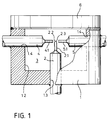
- a fiber-optic light guide 2 is guided through a smaller bore 1.3 coaxial with this bore 1.2 and fixed in the bore 1.3.
- the light guide 2 is freed from the coating so that the bare optical fiber 2.1 projects into the interior 3 of the housing 1.
- the front end of the optical fiber 2.1 is ground in the form of a roof edge prism symmetrical to the longitudinal axis and thus has two end faces 2.2 and 2.3.
- a further bore 1.4 is passed through the housing 1 such that the axes of the bores 1.3 and 1.4 intersect at a point at right angles.
- this bore 1.4 one end of further light guides 4 and 5 is inserted from both sides and connected to the housing wall.
- the ends of the optical fibers 4.1 and 5.1, which are also freed of the sheathing, are as possible close to the intersection of the bores 1.3 and 1.4 and are therefore as close as possible to the end faces 2.2 and 2.3.
- the housing 1 After assembly, the housing 1 is hermetically sealed by a cylindrical cover 6, the interior 3 being purged beforehand by a dried and cleaned inert gas.
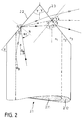
- FIG. 2 shows the tip of the optical fiber 2.1, which in the exemplary embodiment shown is to be a step-index thick-core fiber.
- This consists of a core 2.11 and a jacket 2.12 with the refractive indices n1 and n2.
- the core diameter is typically 200 ⁇ m
- the outer diameter of the jacket 2.12 is approximately 280 ⁇ m.
- the end face of the optical fiber 1 is ground symmetrically in the form of a roof prism, the ground angle ⁇ to the longitudinal axis of the fiber being the same for both surfaces 2.2 and 2.3.
- the formation of the end face of the optical fiber into a prism could also be produced by a pressing process.
- the light guided in the optical fiber 2.1 must now meet the condition with regard to its “acceptance angle” ⁇ B within the fiber core or converted fulfill.
- the term "acceptance angle” is therefore placed in quotation marks in order to distinguish it from the acceptance angle usually used for the coupling of light into the fiber.
- the angles ⁇ B and ⁇ T thus set the limits for the bevel angle ⁇ .
- the following applies to the upper limit ⁇ max : ⁇ Max 90 ° - ⁇ B - ⁇ T (5) or
- the lower limit ⁇ min of the grinding angle can be seen with the following consideration: Starting from a light beam running parallel to the fiber axis, which was reflected at point P 1 on surface 2.2, this reflected beam forms an angle 3 ⁇ on surface 2.3. A beam deviating from the longitudinal axis of the fiber by the "acceptance angle" ⁇ B then forms an angle 3 ⁇ - ⁇ B with the interface 2.3. In the limit case, the difference of this angle with the limit angle ⁇ T for total reflection forms a right angle to the normal N of the surface 2.2.
- the distribution of the beam intensities depends both on the adjustment of the optical axes of the light guides 4 and 5 with respect to the surfaces 2.2 and 2.3 and on the distance between the surfaces 2.2 and 2.3 of the respective opposite end faces of the fibers 4.1 and 5.1.
- Fig. 1 the absolute dimensions of the light guide and the housing are shown considerably enlarged compared to the original dimensions, but the relationships to each other are roughly reproduced. This means that with the above-mentioned fiber diameter of approx. 280 ⁇ m, the housing dimensions are approximately 4 mm in diameter and 2.5 mm in height.
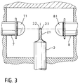
- a light-emitting diode 7 and a photodiode 8 are placed at a right angle to the longitudinal axis of the fiber in a housing similar to that in FIG. 1 and therefore not shown in detail, the light guide 2 with optical fiber 2.1 ground on a prism shape.
- the light-emitting diode 7 and the photodiode 8 have lenses 7.1 and 8.1, respectively, and are arranged with respect to their distance from the corresponding surfaces 2.2 and 2.3 of the optical fiber 2.1 such that the luminous surface or the photosensitive surface are imaged on these surfaces 2.2 and 2.3.
- the device shown can thus be used as an optoelectric transmitting or receiving device, only one optical fiber being required for the signal transport, since this is designed as a beam splitter in accordance with the previous exemplary embodiment.
Claims (5)
- Dispositif à fibre optique pour le couplage ou le découplage de lumière, de la lumière pouvant être couplée dans ou découplée d'une fibre optique dans différentes directions de l'environnement de la fibre optique, composé d'une fibre (2.1) avec un coeur (2.11) et une gaine (2.12), caractérisé par le fait que la surface frontale de la fibre optique (2.1) est pourvue d'au moins deux faces (2.2, 2.3) frontales planes inclinées l'une par rapport à l'autre, l'angle (alpha) entre l'axe longitudinal de la fibre et l'une des faces frontales (2.2, 2.3) satisfaisant la condition

n₁= Indice de réfraction du coeur de la fibre
n₂= Indice de réfraction de la gaine de la fibre
n₃= Indice de réfraction du milieu entourant la fibre - Diviseur de rayons à fibre optique selon la revendication 1, caractérisé par le fait que l'angle γ satisfait la condition

- Diviseur de rayons à fibres optiques selon la revendication 1 ou 2, caractérisé par le fait que la surface frontale des fibres optiques est agencée sous la forme de prisme triangulaire, les normales (N) aux surfaces du prisme triangulaire (2.2. 2.3) et l'axe longitudinal de la fibre étant coplanaires et les angles γ des différentes surfaces du prisme triangulaire étant égaux.
- Coupleur à fibre optique comportant un dispositif à fibres optiques selon l'une des revendications 1 à 3, caractérisé par le fait qu'une face frontale d'une fibre optique (4.1, 5.1) est disposée en regard chaque fois de l'une des faces frontales du dispositif de telle sorte que de la lumière soit couplée du dispositif dans les fibres optiques ou des fibres optiques dans le dispositif.
- Dispositif d'émission et de réception opto-électronique comportant un dispositif à fibre optique selon l'une des revendications 1 à 3, caractérisé par le fait qu'une diode électro-luminescente (7) ou une photodiode (8) est disposée en regard d'au moins une des surfaces frontales du dispositif de telle sorte que de la lumière soit couplée du dispositif dans la photodiode (8) ou de la diode électro-luminescente (7) dans le dispositif.
Applications Claiming Priority (2)
| Application Number | Priority Date | Filing Date | Title |
|---|---|---|---|
| DE3908530 | 1989-03-16 | ||
| DE3908530A DE3908530C1 (fr) | 1989-03-16 | 1989-03-16 |
Publications (3)
| Publication Number | Publication Date |
|---|---|
| EP0387413A2 EP0387413A2 (fr) | 1990-09-19 |
| EP0387413A3 EP0387413A3 (fr) | 1991-07-10 |
| EP0387413B1 true EP0387413B1 (fr) | 1994-10-12 |
Family
ID=6376435
Family Applications (1)
| Application Number | Title | Priority Date | Filing Date |
|---|---|---|---|
| EP89122940A Expired - Lifetime EP0387413B1 (fr) | 1989-03-16 | 1989-12-12 | Séparateur de faisceaux à fibre optique |
Country Status (4)
| Country | Link |
|---|---|
| US (1) | US4995694A (fr) |
| EP (1) | EP0387413B1 (fr) |
| DE (2) | DE3908530C1 (fr) |
| ES (1) | ES2064420T3 (fr) |
Cited By (1)
| Publication number | Priority date | Publication date | Assignee | Title |
|---|---|---|---|---|
| JP2009098338A (ja) * | 2007-10-16 | 2009-05-07 | Fujikura Ltd | 光ファイバ及び一心双方向光送受信モジュール |
Families Citing this family (5)
| Publication number | Priority date | Publication date | Assignee | Title |
|---|---|---|---|---|
| DE4230224A1 (de) * | 1992-09-10 | 1994-03-17 | Bundesrep Deutschland | Strahlaufspaltungs- und Fokussierungsoptik |
| US5440655A (en) * | 1993-12-29 | 1995-08-08 | At&T Corp. | Optical fiber connector bypass device and method using same |
| DE19616932A1 (de) * | 1996-04-27 | 1997-10-30 | Bosch Gmbh Robert | Optisches, strahlteilendes Bauelement sowie Verfahren zur Herstellung einer Prismenträgerplatte für ein solches Bauelement |
| GB0103124D0 (en) * | 2001-02-08 | 2001-03-28 | Kymata Ltd | A variable optical attenuator |
| US20220137310A1 (en) * | 2020-11-03 | 2022-05-05 | Amrita Vishwa Vidyapeetham | Circular Optical Array System Using Waveguide Fed Angled Mirrors |
Family Cites Families (11)
| Publication number | Priority date | Publication date | Assignee | Title |
|---|---|---|---|---|
| US3508165A (en) * | 1965-11-17 | 1970-04-21 | O Van Nicolai | Claddings for lasers |
| US3505613A (en) * | 1966-08-22 | 1970-04-07 | Minnesota Mining & Mfg | Zinc oxide laser |
| US4176908A (en) * | 1977-12-14 | 1979-12-04 | Bell Telephone Laboratories, Incorporated | Devices for monitoring, switching, attenuating or distributing light |
| DE2938649A1 (de) * | 1978-09-28 | 1980-04-10 | Australian Telecomm | Vorrichtung und verfahren zur signaluebertragung in lichtleitern |
| DE2929186A1 (de) * | 1979-07-19 | 1981-02-05 | Licentia Gmbh | Einrichtung zur auskopplung eines definierten anteils eines lichtbuendels einer lichtleitfaser |
| US4413879A (en) * | 1979-10-15 | 1983-11-08 | The United States Of America As Represented By The Director Of The National Security Agency | Method and apparatus for side launch excitation of selected modes in graded-index optical fibers |
| JPS57204507A (en) * | 1981-06-12 | 1982-12-15 | Nec Corp | Interference film type optical multiplexer and demultiplexer |
| FR2586305A1 (fr) * | 1985-08-19 | 1987-02-20 | Lignes Telegraph Telephon | Coupleur bidirectionnel pour liaison par fibres optiques |
| EP0220455A1 (fr) * | 1985-09-24 | 1987-05-06 | Siemens Aktiengesellschaft | Dispositif de couplage entre une diode laser et un guide d'onde monomode |
| IT1202608B (it) * | 1987-03-02 | 1989-02-09 | Pirelli Cavi Spa | Accoppiatore bidirezionale tra tre guide d'onda ottiche |
| US4883333A (en) * | 1987-10-13 | 1989-11-28 | Yanez Serge J | Integrated, solid, optical device |
-
1989
- 1989-03-16 DE DE3908530A patent/DE3908530C1/de not_active Expired - Lifetime
- 1989-12-12 ES ES89122940T patent/ES2064420T3/es not_active Expired - Lifetime
- 1989-12-12 EP EP89122940A patent/EP0387413B1/fr not_active Expired - Lifetime
- 1989-12-12 DE DE58908505T patent/DE58908505D1/de not_active Expired - Fee Related
-
1990
- 1990-03-16 US US07/494,630 patent/US4995694A/en not_active Expired - Lifetime
Cited By (1)
| Publication number | Priority date | Publication date | Assignee | Title |
|---|---|---|---|---|
| JP2009098338A (ja) * | 2007-10-16 | 2009-05-07 | Fujikura Ltd | 光ファイバ及び一心双方向光送受信モジュール |
Also Published As
| Publication number | Publication date |
|---|---|
| US4995694A (en) | 1991-02-26 |
| EP0387413A3 (fr) | 1991-07-10 |
| EP0387413A2 (fr) | 1990-09-19 |
| ES2064420T3 (es) | 1995-02-01 |
| DE58908505D1 (de) | 1994-11-17 |
| DE3908530C1 (fr) | 1990-08-09 |
Similar Documents
| Publication | Publication Date | Title |
|---|---|---|
| EP0238977B1 (fr) | Module émission-réception pour un réseau de communication bidirectionnelle, particulièrement un RNIS à large bande | |
| DE3241774C2 (fr) | ||
| CH644975A5 (de) | Lichtleitfaser-richtkoppler und dessen verwendung in einer sende-/empfangseinrichtung. | |
| DE2753222A1 (de) | Optische kupplungsvorrichtung | |
| DE2159327B2 (de) | Vorrichtung zur Justierung zweier optischer Bauelemente | |
| DE2914262A1 (de) | Optisches daempfungsglied fuer lichtleitfasern | |
| DE2703319A1 (de) | Opto-elektrische abzweigungsvorrichtung und verfahren zu ihrer herstellung | |
| DE69734800T2 (de) | Faseroptisches Element, lichtempfangendes Element, und Vorrichtung zur Mustererfassung | |
| EP0655619A1 (fr) | Système de détection | |
| DE3704603A1 (de) | Lichtwellenleiter-schleifringvorrichtung | |
| DE2905916A1 (de) | Faseroptische uebertragungsvorrichtung | |
| DE3508390C2 (fr) | ||
| EP0387413B1 (fr) | Séparateur de faisceaux à fibre optique | |
| DE2653815A1 (de) | Koppler zur verbindung eines beliebigen lichtleiters mit allen anderen lichtleitern eines buendels | |
| DE60221258T2 (de) | Ausrichtungssystem für faseroptisches kabel | |
| EP0078029B1 (fr) | Connexion pour fibres optiques | |
| DE3704162C2 (fr) | ||
| EP2056144B1 (fr) | Elément d'extrémité pour fibres optiques | |
| CH680020A5 (fr) | ||
| EP0304993B1 (fr) | Dispositif de couplage dirigeant un faisceau lumineux émis par l'extrémité d'un guide d'onde vers la surface sensible à la lumière d'une photodiode d'un instrument de mesure | |
| DE69733535T2 (de) | Optischer Glasfaserblock | |
| DE2931530A1 (de) | Anordnung zur auskopplung von licht aus einer lichtleitfaser-uebertragungsstrecke | |
| DE3151108A1 (de) | Optisches beleuchtungssystem | |
| DD242105A1 (de) | Beleuchtungseinrichtung fuer mikroskope und projektoren | |
| DE112015007049B4 (de) | Optisches Element |
Legal Events
| Date | Code | Title | Description |
|---|---|---|---|
| PUAI | Public reference made under article 153(3) epc to a published international application that has entered the european phase |
Free format text: ORIGINAL CODE: 0009012 |
|
| AK | Designated contracting states |
Kind code of ref document: A2 Designated state(s): DE ES GB IT |
|
| 17P | Request for examination filed |
Effective date: 19901128 |
|
| PUAL | Search report despatched |
Free format text: ORIGINAL CODE: 0009013 |
|
| AK | Designated contracting states |
Kind code of ref document: A3 Designated state(s): DE ES GB IT |
|
| RAP1 | Party data changed (applicant data changed or rights of an application transferred) |
Owner name: DEUTSCHE AEROSPACE AKTIENGESELLSCHAFT |
|
| 17Q | First examination report despatched |
Effective date: 19930805 |
|
| GRAA | (expected) grant |
Free format text: ORIGINAL CODE: 0009210 |
|
| AK | Designated contracting states |
Kind code of ref document: B1 Designated state(s): DE ES GB IT |
|
| REF | Corresponds to: |
Ref document number: 58908505 Country of ref document: DE Date of ref document: 19941117 |
|
| GBT | Gb: translation of ep patent filed (gb section 77(6)(a)/1977) |
Effective date: 19941129 |
|
| ITF | It: translation for a ep patent filed |
Owner name: STUDIO JAUMANN |
|
| REG | Reference to a national code |
Ref country code: ES Ref legal event code: FG2A Ref document number: 2064420 Country of ref document: ES Kind code of ref document: T3 |
|
| RAP2 | Party data changed (patent owner data changed or rights of a patent transferred) |
Owner name: DAIMLER-BENZ AEROSPACE AKTIENGESELLSCHAFT |
|
| PLBE | No opposition filed within time limit |
Free format text: ORIGINAL CODE: 0009261 |
|
| STAA | Information on the status of an ep patent application or granted ep patent |
Free format text: STATUS: NO OPPOSITION FILED WITHIN TIME LIMIT |
|
| 26N | No opposition filed | ||
| REG | Reference to a national code |
Ref country code: GB Ref legal event code: 732E |
|
| REG | Reference to a national code |
Ref country code: ES Ref legal event code: PC2A |
|
| REG | Reference to a national code |
Ref country code: GB Ref legal event code: IF02 |
|
| PGFP | Annual fee paid to national office [announced via postgrant information from national office to epo] |
Ref country code: GB Payment date: 20021128 Year of fee payment: 14 |
|
| PGFP | Annual fee paid to national office [announced via postgrant information from national office to epo] |
Ref country code: ES Payment date: 20021212 Year of fee payment: 14 |
|
| PGFP | Annual fee paid to national office [announced via postgrant information from national office to epo] |
Ref country code: DE Payment date: 20021218 Year of fee payment: 14 |
|
| PG25 | Lapsed in a contracting state [announced via postgrant information from national office to epo] |
Ref country code: GB Free format text: LAPSE BECAUSE OF NON-PAYMENT OF DUE FEES Effective date: 20031212 |
|
| PG25 | Lapsed in a contracting state [announced via postgrant information from national office to epo] |
Ref country code: ES Free format text: LAPSE BECAUSE OF NON-PAYMENT OF DUE FEES Effective date: 20031213 |
|
| PG25 | Lapsed in a contracting state [announced via postgrant information from national office to epo] |
Ref country code: DE Free format text: LAPSE BECAUSE OF NON-PAYMENT OF DUE FEES Effective date: 20040701 |
|
| GBPC | Gb: european patent ceased through non-payment of renewal fee |
Effective date: 20031212 |
|
| REG | Reference to a national code |
Ref country code: ES Ref legal event code: FD2A Effective date: 20031213 |
|
| PG25 | Lapsed in a contracting state [announced via postgrant information from national office to epo] |
Ref country code: IT Free format text: LAPSE BECAUSE OF NON-PAYMENT OF DUE FEES;WARNING: LAPSES OF ITALIAN PATENTS WITH EFFECTIVE DATE BEFORE 2007 MAY HAVE OCCURRED AT ANY TIME BEFORE 2007. THE CORRECT EFFECTIVE DATE MAY BE DIFFERENT FROM THE ONE RECORDED. Effective date: 20051212 |