EP0385455A1 - Unstacking and stacking device - Google Patents
Unstacking and stacking device Download PDFInfo
- Publication number
- EP0385455A1 EP0385455A1 EP90103947A EP90103947A EP0385455A1 EP 0385455 A1 EP0385455 A1 EP 0385455A1 EP 90103947 A EP90103947 A EP 90103947A EP 90103947 A EP90103947 A EP 90103947A EP 0385455 A1 EP0385455 A1 EP 0385455A1
- Authority
- EP
- European Patent Office
- Prior art keywords
- containers
- lifting frame
- stack
- roller conveyor
- fingerlike
- Prior art date
- Legal status (The legal status is an assumption and is not a legal conclusion. Google has not performed a legal analysis and makes no representation as to the accuracy of the status listed.)
- Granted
Links
Images


Classifications
-
- B—PERFORMING OPERATIONS; TRANSPORTING
- B65—CONVEYING; PACKING; STORING; HANDLING THIN OR FILAMENTARY MATERIAL
- B65G—TRANSPORT OR STORAGE DEVICES, e.g. CONVEYORS FOR LOADING OR TIPPING, SHOP CONVEYOR SYSTEMS OR PNEUMATIC TUBE CONVEYORS
- B65G57/00—Stacking of articles
- B65G57/30—Stacking of articles by adding to the bottom of the stack
- B65G57/301—Stacking of articles by adding to the bottom of the stack by means of reciprocatory or oscillatory lifting and holding or gripping devices
- B65G57/303—Stacking of articles by adding to the bottom of the stack by means of reciprocatory or oscillatory lifting and holding or gripping devices the stack being lowered by mobile grippers or holders onto added articles
-
- B—PERFORMING OPERATIONS; TRANSPORTING
- B65—CONVEYING; PACKING; STORING; HANDLING THIN OR FILAMENTARY MATERIAL
- B65G—TRANSPORT OR STORAGE DEVICES, e.g. CONVEYORS FOR LOADING OR TIPPING, SHOP CONVEYOR SYSTEMS OR PNEUMATIC TUBE CONVEYORS
- B65G59/00—De-stacking of articles
- B65G59/06—De-stacking from the bottom of the stack
- B65G59/061—De-stacking from the bottom of the stack articles being separated substantially along the axis of the stack
- B65G59/062—De-stacking from the bottom of the stack articles being separated substantially along the axis of the stack by means of reciprocating or oscillating escapement-like mechanisms
- B65G59/063—De-stacking from the bottom of the stack articles being separated substantially along the axis of the stack by means of reciprocating or oscillating escapement-like mechanisms comprising lifting means
Definitions
- the present invention relates to an unstacking and stacking device respectively for handling four transport containers at a time.
- the invention is intended for unstacking of containers from a pallet respectively stacking of containers on a pallet.
- pallets it is not necessary to use pallets in connection with the present invention.
- Stacking devices where one transport container is stacked at a time have been known for a long time.
- goods are transported in small containers, which are then stacked on pallets.
- the pallets make a rational handling via different kinds of fork lift trucks possible.
- the transport containers which usually are made of plastic, also give a rational handling of goods.
- the device comprises a lifting frame, one side of which can be opened.
- the frame is movably fixed to a stand in such a manner that it can be operated vertically.
- a number of finger like means are arranged on the frame. These means can be maneuvered horizontally and are intended to engage with two adjacent sides of each container.
- a number of layers of containers arranged four and four on top of each other in a stack, preferably on a pallet, are intended to be fed into the lifting frame by means of a roller conveyor, a conveying belt etc., whereupon the side of the lifting frame which can be opened, has first been opened. Then the roller conveyor is stopped, whereupon the opened side is closed and the lifting frame is adjusted to the right level of height.
- the finger like means are now extended towards the containers in such a way that they will engage with the upper border of the containers in the lowermost layer of containers.
- the fingerlike means are extended towards the containers again in such a way that they will engage with the upper borders of the second lowermost layer of containers.
- the stack of containers is now lifted up, whereupon the roller conveyor is started and the lowermost layer of containers is fed out of the device.
- the front side of the lifting frame which side can be opened, can be maneuvered in the horizontal or the vertical plane. Then the front side can consist of a whole or a two-piece bar.
- the fingerlike means are provided with an upper and a lower leg, whereby the upper border of the containers is intended to the placed between these legs.
- the whole lifting frame including the front side, which can be opened, and the fingerlike means can be operated in a mechanical way, for example by means of motion by motor and gear wheels, in a hydraulic or in a pneumatic way.
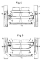
- fig. 1 shows a cross-section through one embodiment of a device according to the invention seen from above.
- Figures 2-6 show a cross-section through the device according to fig. 1 seen from the front.
- Figures 2-6 illustrate a successive unstacking of containers from a pallet.
- Fig. 7 shows a perspective view of a device according to fig. 1 with a stack consisting of two layers of containers, which has been lifted up.
- the device according to the invention comprises a lifting frame 1, one end 2 of which can be opened.
- the frame 1 is movably fixed to a stand 3 in such a manner that it can be operated vertically.
- a number of fingerlike means 4 are arranged on the frame 1.
- a stack consisting of a number of layers of containers 5, 6, 7 and 8 is arranged inside the frame 1.
- the containers 5, 6, 7 and 8 are placed together four and four on top of each other on a pallet 9 (figs. 2 and 3).
- the fingerlike means 4 can be operated horizontally and are intended to engage with two adjacent sides of each container 5, 6, 7 and 8. As illustrated on fig. 1, there are fingerlike means 4 along all four sides of the frame 1.
- the fingerlike means 4 are provided with an upper 12 and a lower leg 13.
- the upper border 11 of the containers is intended to be placed between the legs 12 and 13. In this way the containers can be lifted up and down in a safe way in spite of the fact that the fingerlike means 4 can only engage with two adjacent sides of each container. Since the containers are placed four and four together, they will support each other at the handling in the stacking device.
- the means 4 can be shaped in another way than with legs 12 and 13 and cooperate with another part of the containers than the upper border 11, for example with an outwards directed part formed along the outer surfaces of the containers.
- the stack of containers has been fed into the lifting frame 1 by means of a roller conveyor, a conveying belt etc. 10.
- the side 2 has then been opened first. This can be made by opening the side 2 vertically or outwards in the horizontal plane. Generally, it is most advantageous if the side 2, which usually has the form of a bar 2 is maneuvered vertically. Then it will occupy the smallest space.
- the bar can be simple or divided in two bars.
- the lifting frame 1 (see fig. 2) is adjusted to the right level of height, whereupon the fingerlike means 4 are extended towards the containers 5, 6, 7 and 8 (5 and 7 cannot be seen), in such a way that they will preferably engage with the upper border 11 of the containers in the lowermost layer of containers on the pallet 9.
- the whole stack of containers is now lifted up (see fig. 3), whereupon the pallet 9 is fed out of the device.
- the roller conveyor 10 is now stopped, whereupon the stack of containers is put down on the roller conveyor 10 by lowering the lifting frame 1 (see fig. 4).
- the stack of containers is now lifted up (see fig. 6), whereupon the roller conveyor is started.
- the first layer of containers is fed out of the device, whereupon the procedure is repeated until all layers of containers 5, 6, 7 and 8 have been fed out of the device and a new stack can be fed in.
- the device can be used for stacking one container at a time, whereby the container has about the same size as the pallet. It is also possible to stack two containers at a time. Then, the containers have about half the size of the pallet.
- the device can also be operated as a stacking device instead of an unstacking device. The procedure will then be the opposite of the one disclosed above.
Abstract
Description
- The present invention relates to an unstacking and stacking device respectively for handling four transport containers at a time.
- Preferably, the invention is intended for unstacking of containers from a pallet respectively stacking of containers on a pallet. However, it is not necessary to use pallets in connection with the present invention.
- Stacking devices where one transport container is stacked at a time have been known for a long time. Nowadays, goods are transported in small containers, which are then stacked on pallets. The pallets make a rational handling via different kinds of fork lift trucks possible. The transport containers, which usually are made of plastic, also give a rational handling of goods.
- Often it is desirable to place four containers together and stacked in a suitable number of such layers on top of each other on a pallet. Since the pallets have standard measurements the measurements of the containers have been adapted to these. So far it has been necessary to stack these containers by hand one by one on the pallets. This is a very heavy and monotonous work. It has been a long-felt want to get rid of this work by rationalization. However, it has not been possible to do so.
- According to the present invention it has quite unexpectedly been possible to solve the above problem and bring about an unstacking and stacking device respectively for handling four containers at a time. The device comprises a lifting frame, one side of which can be opened. The frame is movably fixed to a stand in such a manner that it can be operated vertically. A number of finger like means are arranged on the frame. These means can be maneuvered horizontally and are intended to engage with two adjacent sides of each container.
- A number of layers of containers arranged four and four on top of each other in a stack, preferably on a pallet, are intended to be fed into the lifting frame by means of a roller conveyor, a conveying belt etc., whereupon the side of the lifting frame which can be opened, has first been opened. Then the roller conveyor is stopped, whereupon the opened side is closed and the lifting frame is adjusted to the right level of height. The finger like means are now extended towards the containers in such a way that they will engage with the upper border of the containers in the lowermost layer of containers.
- The whole stack of containers is lifted, whereupon the roller conveyor is started and the pallet is fed out of the device. Now the roller conveyor is stopped and the stack of containers is put down on the roller conveyor by lowering the lifting frame. The engagement of the finger like means with the upper boarders is released, whereupon the lifting frame is lifted up to the level of the upper borders of the second lowermost layer of containers.
- The fingerlike means are extended towards the containers again in such a way that they will engage with the upper borders of the second lowermost layer of containers. The stack of containers is now lifted up, whereupon the roller conveyor is started and the lowermost layer of containers is fed out of the device.
- The procedure is now repeated until all layers of containers have been fed out of the device and a new stack can be fed in.
- The front side of the lifting frame, which side can be opened, can be maneuvered in the horizontal or the vertical plane. Then the front side can consist of a whole or a two-piece bar.
- Preferably, the fingerlike means are provided with an upper and a lower leg, whereby the upper border of the containers is intended to the placed between these legs.
- The whole lifting frame including the front side, which can be opened, and the fingerlike means can be operated in a mechanical way, for example by means of motion by motor and gear wheels, in a hydraulic or in a pneumatic way.
- The invention will be explained further in connection with the enclosed figures of which fig. 1 shows a cross-section through one embodiment of a device according to the invention seen from above. Figures 2-6 show a cross-section through the device according to fig. 1 seen from the front. Figures 2-6 illustrate a successive unstacking of containers from a pallet. Fig. 7 shows a perspective view of a device according to fig. 1 with a stack consisting of two layers of containers, which has been lifted up.
- On fig. 1 it is shown that the device according to the invention comprises a
lifting frame 1, oneend 2 of which can be opened. Theframe 1 is movably fixed to astand 3 in such a manner that it can be operated vertically. A number offingerlike means 4 are arranged on theframe 1. - A stack consisting of a number of layers of
containers frame 1. Thecontainers - The
fingerlike means 4 can be operated horizontally and are intended to engage with two adjacent sides of eachcontainer fingerlike means 4 along all four sides of theframe 1. - Preferably, the
fingerlike means 4 are provided with an upper 12 and alower leg 13. The upper border 11 of the containers is intended to be placed between thelegs fingerlike means 4 can only engage with two adjacent sides of each container. Since the containers are placed four and four together, they will support each other at the handling in the stacking device. - Of course, the
means 4 can be shaped in another way than withlegs - The stack of containers has been fed into the lifting
frame 1 by means of a roller conveyor, a conveying belt etc. 10. Theside 2 has then been opened first. This can be made by opening theside 2 vertically or outwards in the horizontal plane. Generally, it is most advantageous if theside 2, which usually has the form of abar 2 is maneuvered vertically. Then it will occupy the smallest space. The bar can be simple or divided in two bars. - When the stack is on its place in the
lifting frame 1, theroller conveyor 10 is stopped and thebar 2 is closed. - The lifting frame 1 (see fig. 2) is adjusted to the right level of height, whereupon the
fingerlike means 4 are extended towards thecontainers - The whole stack of containers is now lifted up (see fig. 3), whereupon the pallet 9 is fed out of the device. The
roller conveyor 10 is now stopped, whereupon the stack of containers is put down on theroller conveyor 10 by lowering the lifting frame 1 (see fig. 4). - The engagement of the
fingerlike means 4 with the upper border 11 is released, whereupon thelifting frame 1 is lifted up to the level of the upper borders 11 of the second lowermost layer ofcontainers - The stack of containers is now lifted up (see fig. 6), whereupon the roller conveyor is started. The first layer of containers is fed out of the device, whereupon the procedure is repeated until all layers of
containers - On the figures it is schematically illustrated that the
lifting frame 1 and thefingerlike means 4 are maneuvered in a mechanical way by means of motion by motor (14) andgear wheels 15 etc. However, as mentioned above, it is possible to use hydraulics and pneumatic instead for the operation. Combinations of mechanics, hydraulics and pneumatic are also possible. - The invention is not limited to the embodiment shown, since this can be modified in different ways within the scope of the invention. For example, the device can be used for stacking one container at a time, whereby the container has about the same size as the pallet. It is also possible to stack two containers at a time. Then, the containers have about half the size of the pallet.
- Moreover, the device can also be operated as a stacking device instead of an unstacking device. The procedure will then be the opposite of the one disclosed above.
- Reference signs in the claims are intended for better understanding and shall not limit the scope.
Claims (5)
Priority Applications (1)
| Application Number | Priority Date | Filing Date | Title |
|---|---|---|---|
| AT90103947T ATE97096T1 (en) | 1989-03-01 | 1990-03-01 | DESTACKING OR. STACKING DEVICE. |
Applications Claiming Priority (2)
| Application Number | Priority Date | Filing Date | Title |
|---|---|---|---|
| SE8900700 | 1989-03-01 | ||
| SE8900700A SE463206B (en) | 1989-03-01 | 1989-03-01 | DISAPPOINTING RESP |
Publications (2)
| Publication Number | Publication Date |
|---|---|
| EP0385455A1 true EP0385455A1 (en) | 1990-09-05 |
| EP0385455B1 EP0385455B1 (en) | 1993-11-10 |
Family
ID=20375191
Family Applications (1)
| Application Number | Title | Priority Date | Filing Date |
|---|---|---|---|
| EP90103947A Expired - Lifetime EP0385455B1 (en) | 1989-03-01 | 1990-03-01 | Unstacking and stacking device |
Country Status (5)
| Country | Link |
|---|---|
| EP (1) | EP0385455B1 (en) |
| AT (1) | ATE97096T1 (en) |
| DE (1) | DE69004457T2 (en) |
| ES (1) | ES2048345T3 (en) |
| SE (1) | SE463206B (en) |
Cited By (10)
| Publication number | Priority date | Publication date | Assignee | Title |
|---|---|---|---|---|
| EP0603975A1 (en) * | 1992-12-23 | 1994-06-29 | Harry Christiaan Piepers | A method and a device for cleaning containers |
| WO1999001362A1 (en) * | 1997-07-03 | 1999-01-14 | Gea Till Gmbh & Co. | Method and device for palletizing packing drums on a load platform and/or depalletizing of said packing drums |
| NL1008549C2 (en) * | 1998-03-10 | 1999-09-13 | Bouwe Prakken | Device for stacking and destacking crates. |
| GB2358383A (en) * | 1999-12-10 | 2001-07-25 | Kensal Ltd | Apparatus for transferring stacks of containers onto pallets |
| WO2009043432A1 (en) * | 2007-09-30 | 2009-04-09 | Knapp Logistik Automation Gmbh | Method and device for automatically supplying packages that have been sorted by type to a column stacker, preferably in a sorting system |
| CN104554911A (en) * | 2015-01-07 | 2015-04-29 | 江苏迅捷装具科技有限公司 | Single-tab mute basket distributor |
| CN104609197A (en) * | 2015-02-02 | 2015-05-13 | 广运机电(苏州)有限公司 | Transferring, shifting and collection method for goods |
| CN105775722A (en) * | 2016-05-18 | 2016-07-20 | 邯郸美的制冷设备有限公司 | Storage and distribution device for pallets |
| CN106743697A (en) * | 2016-12-23 | 2017-05-31 | 安徽普伦智能装备有限公司 | One kind is used for Carrier box automatic stacking device |
| CN107585581A (en) * | 2017-09-08 | 2018-01-16 | 山东鼎泰盛食品工业装备股份有限公司 | A kind of automatic disc stack of low level, tear disk device open |
Families Citing this family (3)
| Publication number | Priority date | Publication date | Assignee | Title |
|---|---|---|---|---|
| CN103662851B (en) * | 2013-03-26 | 2016-05-04 | 厦门展科电子科技有限公司 | Tear open, the method for stacking casing and implement mechanism and the equipment of the method |
| CN104003184B (en) * | 2014-04-29 | 2016-09-07 | 雄华机械(苏州)有限公司 | A kind of device that cylinder block is separated with pallet |
| CN104444397B (en) * | 2014-10-30 | 2016-06-29 | 烟台烟大众智知识产权服务有限公司 | A kind of mounting of washing machine automatic wire charging installation system |
Citations (4)
| Publication number | Priority date | Publication date | Assignee | Title |
|---|---|---|---|---|
| DE1144190B (en) * | 1959-01-05 | 1963-02-21 | Leifeld & Lemke Maschf | Machine for de-stacking boxes with laterally grasping gripper arms |
| AT229227B (en) * | 1962-03-29 | 1963-08-26 | Kumag A G Maschinenfabrik | Pallet magazine |
| GB1574036A (en) * | 1978-04-27 | 1980-09-03 | Mechstan Eng Co Ltd | Mechanical handling device |
| DE3702708A1 (en) * | 1987-01-30 | 1988-08-11 | Neubecker Maschf C A | Apparatus for palletising and depalletising cylindrical barrels |
-
1989
- 1989-03-01 SE SE8900700A patent/SE463206B/en not_active IP Right Cessation
-
1990
- 1990-03-01 AT AT90103947T patent/ATE97096T1/en not_active IP Right Cessation
- 1990-03-01 DE DE90103947T patent/DE69004457T2/en not_active Expired - Fee Related
- 1990-03-01 EP EP90103947A patent/EP0385455B1/en not_active Expired - Lifetime
- 1990-03-01 ES ES90103947T patent/ES2048345T3/en not_active Expired - Lifetime
Patent Citations (4)
| Publication number | Priority date | Publication date | Assignee | Title |
|---|---|---|---|---|
| DE1144190B (en) * | 1959-01-05 | 1963-02-21 | Leifeld & Lemke Maschf | Machine for de-stacking boxes with laterally grasping gripper arms |
| AT229227B (en) * | 1962-03-29 | 1963-08-26 | Kumag A G Maschinenfabrik | Pallet magazine |
| GB1574036A (en) * | 1978-04-27 | 1980-09-03 | Mechstan Eng Co Ltd | Mechanical handling device |
| DE3702708A1 (en) * | 1987-01-30 | 1988-08-11 | Neubecker Maschf C A | Apparatus for palletising and depalletising cylindrical barrels |
Cited By (16)
| Publication number | Priority date | Publication date | Assignee | Title |
|---|---|---|---|---|
| EP0603975A1 (en) * | 1992-12-23 | 1994-06-29 | Harry Christiaan Piepers | A method and a device for cleaning containers |
| WO1999001362A1 (en) * | 1997-07-03 | 1999-01-14 | Gea Till Gmbh & Co. | Method and device for palletizing packing drums on a load platform and/or depalletizing of said packing drums |
| US6264421B1 (en) * | 1997-07-03 | 2001-07-24 | Gea Till Gmbh & Co. | Apparatus for palletizing containers on a load carrier and/or depalletizing containers |
| NL1008549C2 (en) * | 1998-03-10 | 1999-09-13 | Bouwe Prakken | Device for stacking and destacking crates. |
| GB2358383A (en) * | 1999-12-10 | 2001-07-25 | Kensal Ltd | Apparatus for transferring stacks of containers onto pallets |
| WO2009043432A1 (en) * | 2007-09-30 | 2009-04-09 | Knapp Logistik Automation Gmbh | Method and device for automatically supplying packages that have been sorted by type to a column stacker, preferably in a sorting system |
| US20100198393A1 (en) * | 2007-09-30 | 2010-08-05 | Karl Freudelsperger | Process and device for automatically feeding containers of the same kind to a column stacker, preferably in a sorter system |
| US8401695B2 (en) | 2007-09-30 | 2013-03-19 | Knapp Ag | Process and device for automatically feeding containers of the same kind to a column stacker, preferably in a sorter system |
| CN104554911A (en) * | 2015-01-07 | 2015-04-29 | 江苏迅捷装具科技有限公司 | Single-tab mute basket distributor |
| CN104554911B (en) * | 2015-01-07 | 2016-08-24 | 江苏迅捷装具科技有限公司 | Single quiet Basket dispatching machine of blade inserting |
| CN104609197A (en) * | 2015-02-02 | 2015-05-13 | 广运机电(苏州)有限公司 | Transferring, shifting and collection method for goods |
| CN104609197B (en) * | 2015-02-02 | 2017-05-10 | 广运机电(苏州)有限公司 | Transferring, shifting and collection method for goods |
| CN105775722A (en) * | 2016-05-18 | 2016-07-20 | 邯郸美的制冷设备有限公司 | Storage and distribution device for pallets |
| CN106743697A (en) * | 2016-12-23 | 2017-05-31 | 安徽普伦智能装备有限公司 | One kind is used for Carrier box automatic stacking device |
| CN106743697B (en) * | 2016-12-23 | 2019-05-28 | 安徽普伦智能装备有限公司 | One kind being used for Carrier box automatic stacking device |
| CN107585581A (en) * | 2017-09-08 | 2018-01-16 | 山东鼎泰盛食品工业装备股份有限公司 | A kind of automatic disc stack of low level, tear disk device open |
Also Published As
| Publication number | Publication date |
|---|---|
| DE69004457T2 (en) | 1994-04-28 |
| SE463206B (en) | 1990-10-22 |
| DE69004457D1 (en) | 1993-12-16 |
| SE8900700L (en) | 1990-09-02 |
| SE8900700D0 (en) | 1989-03-01 |
| ES2048345T3 (en) | 1994-03-16 |
| ATE97096T1 (en) | 1993-11-15 |
| EP0385455B1 (en) | 1993-11-10 |
Similar Documents
| Publication | Publication Date | Title |
|---|---|---|
| JP7133571B2 (en) | Storage and transportation system for goods stored on warehouse shelves | |
| EP0385455A1 (en) | Unstacking and stacking device | |
| KR102462888B1 (en) | Robotic object handling system, device and method | |
| US2683010A (en) | Pallet and spacer | |
| CA1265755A (en) | Machine for transferring bins and the like containers | |
| JPS62180836A (en) | Conveying and storing method in stacking flat for glass plate | |
| JPS6152054B2 (en) | ||
| US4690601A (en) | Storage assembly and method of using same | |
| KR101569468B1 (en) | Automatic stacking apparatus for pallet | |
| JPH06509783A (en) | Accumulator cover | |
| US6494313B1 (en) | Stackable open front grocery and goods bin with compressed air cushion mobility | |
| US3628672A (en) | Captive pallet for load-stacking racks | |
| US2704194A (en) | U-bolt locking device | |
| CN206970152U (en) | A kind of novel forklift | |
| US3699900A (en) | Material handling device | |
| JPS6145828A (en) | Device for piling up pallet together with article placed on pallet such as large-sized bag | |
| KR101962792B1 (en) | piling up equipment of mineral water package | |
| US3053403A (en) | Apparatus for storing and handling materials | |
| US2723770A (en) | Device for the storage of piece goods | |
| US4474546A (en) | Box-like pallet, especially for maturing cheese | |
| DE3203757A1 (en) | Apparatus for the intermediate stacking of articles | |
| US3053492A (en) | Storage pallets | |
| JPS6134354Y2 (en) | ||
| DE2520240C3 (en) | palette | |
| CN214826315U (en) | Handling device and warehousing system |
Legal Events
| Date | Code | Title | Description |
|---|---|---|---|
| PUAI | Public reference made under article 153(3) epc to a published international application that has entered the european phase |
Free format text: ORIGINAL CODE: 0009012 |
|
| AK | Designated contracting states |
Kind code of ref document: A1 Designated state(s): AT BE CH DE DK ES FR GB GR IT LI LU NL SE |
|
| 17P | Request for examination filed |
Effective date: 19910208 |
|
| 17Q | First examination report despatched |
Effective date: 19920619 |
|
| GRAA | (expected) grant |
Free format text: ORIGINAL CODE: 0009210 |
|
| ITF | It: translation for a ep patent filed |
Owner name: BARZANO' E ZANARDO MILA |
|
| AK | Designated contracting states |
Kind code of ref document: B1 Designated state(s): AT BE CH DE DK ES FR GB GR IT LI LU NL SE |
|
| PG25 | Lapsed in a contracting state [announced via postgrant information from national office to epo] |
Ref country code: GR Free format text: LAPSE BECAUSE OF FAILURE TO SUBMIT A TRANSLATION OF THE DESCRIPTION OR TO PAY THE FEE WITHIN THE PRESCRIBED TIME-LIMIT Effective date: 19931110 |
|
| REF | Corresponds to: |
Ref document number: 97096 Country of ref document: AT Date of ref document: 19931115 Kind code of ref document: T |
|
| REF | Corresponds to: |
Ref document number: 69004457 Country of ref document: DE Date of ref document: 19931216 |
|
| ET | Fr: translation filed | ||
| REG | Reference to a national code |
Ref country code: GR Ref legal event code: FG4A Free format text: 3009706 |
|
| PG25 | Lapsed in a contracting state [announced via postgrant information from national office to epo] |
Ref country code: GB Effective date: 19940301 Ref country code: DK Effective date: 19940301 Ref country code: AT Effective date: 19940301 |
|
| PG25 | Lapsed in a contracting state [announced via postgrant information from national office to epo] |
Ref country code: SE Free format text: LAPSE BECAUSE OF NON-PAYMENT OF DUE FEES Effective date: 19940302 Ref country code: ES Free format text: LAPSE BECAUSE OF NON-PAYMENT OF DUE FEES Effective date: 19940302 |
|
| REG | Reference to a national code |
Ref country code: ES Ref legal event code: FG2A Ref document number: 2048345 Country of ref document: ES Kind code of ref document: T3 |
|
| PG25 | Lapsed in a contracting state [announced via postgrant information from national office to epo] |
Ref country code: LU Free format text: LAPSE BECAUSE OF NON-PAYMENT OF DUE FEES Effective date: 19940331 Ref country code: LI Effective date: 19940331 Ref country code: CH Effective date: 19940331 Ref country code: BE Effective date: 19940331 |
|
| PLBE | No opposition filed within time limit |
Free format text: ORIGINAL CODE: 0009261 |
|
| STAA | Information on the status of an ep patent application or granted ep patent |
Free format text: STATUS: NO OPPOSITION FILED WITHIN TIME LIMIT |
|
| BERE | Be: lapsed |
Owner name: PERSTORP A.B. Effective date: 19940331 |
|
| PG25 | Lapsed in a contracting state [announced via postgrant information from national office to epo] |
Ref country code: NL Effective date: 19941001 |
|
| GBPC | Gb: european patent ceased through non-payment of renewal fee |
Effective date: 19940301 |
|
| 26N | No opposition filed | ||
| NLV4 | Nl: lapsed or anulled due to non-payment of the annual fee | ||
| PG25 | Lapsed in a contracting state [announced via postgrant information from national office to epo] |
Ref country code: FR Effective date: 19941130 |
|
| REG | Reference to a national code |
Ref country code: CH Ref legal event code: PL |
|
| PG25 | Lapsed in a contracting state [announced via postgrant information from national office to epo] |
Ref country code: DE Effective date: 19941201 |
|
| REG | Reference to a national code |
Ref country code: FR Ref legal event code: ST |
|
| EUG | Se: european patent has lapsed |
Ref document number: 90103947.9 Effective date: 19941010 |
|
| REG | Reference to a national code |
Ref country code: GR Ref legal event code: MM2A Free format text: 3009706 |
|
| REG | Reference to a national code |
Ref country code: ES Ref legal event code: FD2A Effective date: 20030203 |
|
| PG25 | Lapsed in a contracting state [announced via postgrant information from national office to epo] |
Ref country code: IT Free format text: LAPSE BECAUSE OF NON-PAYMENT OF DUE FEES;WARNING: LAPSES OF ITALIAN PATENTS WITH EFFECTIVE DATE BEFORE 2007 MAY HAVE OCCURRED AT ANY TIME BEFORE 2007. THE CORRECT EFFECTIVE DATE MAY BE DIFFERENT FROM THE ONE RECORDED. Effective date: 20050301 |