EP0384690B1 - Tank washer - Google Patents
Tank washer Download PDFInfo
- Publication number
- EP0384690B1 EP0384690B1 EP90301783A EP90301783A EP0384690B1 EP 0384690 B1 EP0384690 B1 EP 0384690B1 EP 90301783 A EP90301783 A EP 90301783A EP 90301783 A EP90301783 A EP 90301783A EP 0384690 B1 EP0384690 B1 EP 0384690B1
- Authority
- EP
- European Patent Office
- Prior art keywords
- piston
- tank washer
- tank
- axis
- liquid
- Prior art date
- Legal status (The legal status is an assumption and is not a legal conclusion. Google has not performed a legal analysis and makes no representation as to the accuracy of the status listed.)
- Expired - Lifetime
Links
- 230000010355 oscillation Effects 0.000 claims abstract description 10
- 239000007788 liquid Substances 0.000 claims description 53
- 230000008878 coupling Effects 0.000 claims description 5
- 238000010168 coupling process Methods 0.000 claims description 5
- 238000005859 coupling reaction Methods 0.000 claims description 5
- 238000003860 storage Methods 0.000 claims description 4
- 238000010276 construction Methods 0.000 claims description 3
- 230000001960 triggered effect Effects 0.000 claims description 3
- 238000004140 cleaning Methods 0.000 abstract description 6
- 239000008267 milk Substances 0.000 abstract description 2
- 210000004080 milk Anatomy 0.000 abstract description 2
- 235000013336 milk Nutrition 0.000 abstract description 2
- 235000013405 beer Nutrition 0.000 abstract 1
- 239000000126 substance Substances 0.000 abstract 1
- 239000003599 detergent Substances 0.000 description 6
- XLYOFNOQVPJJNP-UHFFFAOYSA-N water Substances O XLYOFNOQVPJJNP-UHFFFAOYSA-N 0.000 description 6
- 230000000694 effects Effects 0.000 description 4
- 239000011435 rock Substances 0.000 description 3
- 239000000243 solution Substances 0.000 description 3
- 239000000463 material Substances 0.000 description 2
- -1 polytetrafluoroethylene Polymers 0.000 description 2
- 229920001343 polytetrafluoroethylene Polymers 0.000 description 2
- 239000004810 polytetrafluoroethylene Substances 0.000 description 2
- 229910001220 stainless steel Inorganic materials 0.000 description 2
- 239000010935 stainless steel Substances 0.000 description 2
- 239000004677 Nylon Substances 0.000 description 1
- 239000007864 aqueous solution Substances 0.000 description 1
- 238000005266 casting Methods 0.000 description 1
- 238000011109 contamination Methods 0.000 description 1
- 238000009826 distribution Methods 0.000 description 1
- 238000005553 drilling Methods 0.000 description 1
- 238000009434 installation Methods 0.000 description 1
- 238000000034 method Methods 0.000 description 1
- 150000002825 nitriles Chemical class 0.000 description 1
- 229920001778 nylon Polymers 0.000 description 1
- 230000003534 oscillatory effect Effects 0.000 description 1
- 239000003973 paint Substances 0.000 description 1
- 229920000642 polymer Polymers 0.000 description 1
- 230000000717 retained effect Effects 0.000 description 1
- 239000008237 rinsing water Substances 0.000 description 1
- 230000000630 rising effect Effects 0.000 description 1
- 239000007921 spray Substances 0.000 description 1
Images


Classifications
-
- B—PERFORMING OPERATIONS; TRANSPORTING
- B08—CLEANING
- B08B—CLEANING IN GENERAL; PREVENTION OF FOULING IN GENERAL
- B08B9/00—Cleaning hollow articles by methods or apparatus specially adapted thereto
- B08B9/08—Cleaning containers, e.g. tanks
- B08B9/093—Cleaning containers, e.g. tanks by the force of jets or sprays
Definitions
- One method of cleaning is to spray the inside surfaces of a tank with jets of detergent and subsequently with jets of water to effect rinsing.
- the distribution of such jets of detergent and water is effected by a tank washer.
- a tank washer is a mechanical device which directs the jets of detergent or water in a predetermined pattern over the inside surfaces of a tank which is to be cleaned.
- the tank washer is operated by the detergent solution or rinsing liquid that passes through it and will run automatically when fed with such liquid. It needs to be clean in design so that it can be left in the product in a tank without contaminating the product. It also needs to be robust if it is to be moved from tank to tank without damage. Such features are part of the design of a tank washer in accordance with this invention.
- Typical tanks that are often cleaned by known tank washers are those employed in breweries, milk processing plants, paint factories and other installations where bulk liquids are stored.
- a tank washer comprising a piston having an axis and immovably connected, in operation, to liquid supply means, a body surrounding said piston and capable of reciprocating movement and rotational movement with respect to the piston, and at least one liquid ejection nozzle mounted on the body and capable in use of oscillating movement with respect to the body, and a mechanism operable by the relative reciprocation between the body and the piston to cause the body to rotate so as to advance around the axis of the piston.
- each such nozzle being capable of oscillation, during operation, through an arc of substantially 60° about a common axis, and said three arcs of oscillation being spaced apart from one another by successive angles of substantially 60°.
- the tank washer has a longitudinal axis, and the axis of the piston about which the body and hence said nozzle or nozzles are advanced rotationally during operation, substantially corresponds to the longitudinal axis of the tank washer.
- each step has a magnitude of substantially 10°.
- a convenient arrangement is that wherein that axis about which the or each nozzle oscillates during operation of the tank washer is afforded by a nozzle tube contained in a transverse hole formed in the body of the tank washer, and wherein the nozzle tube which, during operation, oscillates the or each nozzle, is connected to the liquid supply means by a coupling piece in such a way as to cause oscillation of the nozzle tube upon reciprocation of the body relative to the piston.
- the arrangement is that wherein said body reciprocates relative to the piston which occupies a fixed position relative to a tank that is to be cleaned, and wherein reciprocation of said body is brought about by applying liquid pressure successively to the opposite sides of said piston.
- a pivotally mounted member is provided by which liquid is fed successively to the opposite sides of said piston, bleed holes (XXX,YYY) being provided adjacent each side of said piston for the exhaust of liquid from that region when the latter is not subject to liquid pressure, each bleed hole (XXX,YYY) being smaller in size than is the liquid supply conduit to the region that is drained by the corresponding bleed hole (XXX,YYY).
- valve member is loaded by the storage of energy in at lest one spring and is subsequently triggered to move independently of the action that causes the triggering by releasing said at least one spring.
- an index driver having a hexagonal spiral and is movable relative to a matching spiral formed internally of a scroll so as to cause the body of the tank washer to advance in steps about said axis, the arrangement being such that said index driver is fitted with rollers which will enable slippage to take place readily in one direction of relative rotation and locking to take place in the opposite direction.
- tank washer in accordance with the invention is hanging substantially, vertically in a tank to be cleaned and that it is fed with both cleaning and rinsing liquid from a centrifugal pump connected to a storage tank of such liquid or to the mains in the case of rinsing water.
- a tank washer in accordance with the invention could equally well, however, be inverted-or have a horizontal or even an inclined disposition.
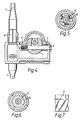
- Figures 3, 10, and 11 also show bleed holes XXX and YYY. These holes form part of the operating system of the tankwasher and are calibrated holes having ports of a size that determine the speed of operation of the tank washer. They will be described in greater detail below.
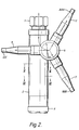
- a tank washer in accordance with the invention is secured in position by means of the internal screw thread of an inlet tube 1.
- a line carrying directional arrows indicates this arrangement in Figure 2 of the drawings.
- the remaining approximately 5% of the detergent solution or rinsing liquid is directed downwardly through a small passage located centrally in the base of the inlet tube 1 and effects the operational movements of parts of the tank washer.
- a broken line indicates this arrangement in Figure 3 of the drawings.
- the operating mechanism of the tank washer oscillates the three nozzles 7 thereof through an arc of 60°.
- the tank washer as a whole indexes in steps about a vertical axis and, typically there will be 36 of these steps to turn the nozzle 7 through a single complete revolution about the vertical centre line of the tank washer, each "step" thus having a magnitude of substantially 10°.
- the nozzles 7 have, in Figure 2 of the drawings been additionally marked AAA,BBB and CCC, respectively.
- the jets of liquid which -issue from them each cover substantially 60° so that the three jets together cover substantially 180°, there being 60° intervals between the three arcs of coverage.
- the jets AAA, BBB and CCC also index progressively around a substantially vertical centre line through 360°, each jet arc actually covers 120°, rather then the 60° which would be covered if no indexing took place.
- the three arcs of coverage together cover 360° so that the total coverage of the inside surface of tank which is being cleaned is attained.
- the tank washer that is being described pumps upwardly and downwardly in addition to progressively rotating, by indexed steps, about a vertical axis substantially coinciding with its own longitudinal axis.
- Several central parts of the tank washer do not move, during operation, relative to the liquid inlet tube 1. Although initially separate, these parts could be considered as being a single entity. Other parts of the tank washer move upwardly and downwardly during the operation of the latter.
- the inlet tube 1 is secured, usually by screw-threads, to a pipe which is fixed to the tank that is to be cleaned and that supplies the cleaning liquid and subsequently the rinsing liquid to the tank washer and the interior of the tank.
- Bearing sleeves 3 which may be made from polytetrafluoroethylene filled polymer are fitted in circumferential grooves in the inlet pipe 1 and are lubricated by the supplied liquid. They act as seals preventing leakage of the liquid to the exterior. Although not shown in the drawings, the seal could be made even better, when required, by fitting the bearing with known nitrile O-rings.
- a main body 2 of the tank washer is fitted over the bearing sleeves 3 and is a single stainless steel casting forming the principal structural frame of the tank washer.
- a nozzle tube 6 is fitted in a cross tube located between the sleeves 3.
- the previously mentioned three nozzles 7 are fitted to the nozzle tube 6 so as to project radially therefrom at 120° intervals around the longitudinal axis of the tube 6.
- Each of the nozzles 7 is fitted with flow guides 8 to improve the "throw" of the lets which issue from it during use.
- the inlet tube 1 and nozzle tube 6 are linked together within the main body 2 by a coupling piece 4 that is secured to the nozzle tube 6 by a bolt 5.
- the main body 2 moves upwardly and downwardly on the relatively fixed inlet tube 1 and is guided in its axial reciprocation by the bearing sleeves 3.
- the coupling piece 4 moves freely within a. large groove in the inlet tube 1 and transmits to the nozzle tubes 6 the 60° oscillation that is derived from this movement, said movement being in the form of a vertical reciprocation.
- a piston rod 10 is screwed into the base of the inlet tube 1 and has a piston 19 secured to it by a lock nut 21.
- the piston 19 is movable in a chamber that is defined in the main body 2 and that is normally sealed closed by a cylinder cap 22, an O-ring 23 being provided for this purpose.
- the exterior of the piston 19 carries a piston seal 20 which acts also as a bearing locating the piston 19 acturately within the chamber that has just been mentioned.
- a differential pressure is created at opposite sides of the piston 19 and will be discussed in detail below.
- this pressure causes the main body 2 to reciprocate upwardly and downwardly with the piston 19 itself remaining in a fixed position. Since the piston 19 is fixedly secured to the inlet tube 1, it may be considered as being part of the tank that is to be cleaned.
- the main body 2 moves relative to this fixed piston 19 and therefore, through the intermediary of the coupling piece 4, oscillates each nozzle 7 through the 60° arc about the longitudinal axis of the tube 6 that has been discussed above.
- the moving parts of the tank washer also index progressively in steps around an axis substantially coinciding with its own vertically disposed longitudinal axis but this movement will be discussed separately below.
- the liquid which operates the tank washer follows substantially the path shown by a broken line in Figure 3 and applies pressure successively to the opposite upper and lower surfaces of the piston 19.
- the piston rod 10 is sealed at either side of the piston 19 by shaft seals 17 and 18 and, as previously mentioned, the operating liquid acts to move the main body 2 upwardly and downwardly.
- the cylinder wall of the main body 2 is provided, at each side of the piston 19, with drilled calibrated holes XXX and YYY, the former hole being the upper one. These holes vent the cylinder space to the atmosphere internally of the tank that is being cleaned. They are “constant exhaust holes" and are substantially smaller in size than are the holes through which the liquid is directed that pressurizes the top and bottom of the piston 19.
- the operating liquid follows the broken path that can be seen in Figure 3 of the drawings and moves downwardly right through the centre of the piston rod 19 and into the lower chamber ZZ that is closed by the cap 9.
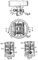
- This chamber ZZ is connected to the spaces both above and below the piston 19 by two drilled passages 33 and 34 that can be seen in Figures 10 and 11 of the drawings.
- Figure 10 shows how one passage 33 directs the liquid from the chamber ZZ to the space above the piston 19 through a hole in the rod 10
- Figure 11 shows the drilling of the passage 34 through the piston rod 10 to connect the chamber ZZ in the cap 9 to the lower surface of the piston 19.
- a pivot post 26 is fitted at right angles to the piston rod 10 and is locked in position by a grub screw ( Figures 8 and 9).
- the pivot post 26 has axially extending "V" grooves milled into its surface and the valve 24 exhibits male pivot points which straddle the piston rod 10 and enable that valve to rock within female "V” grooves formed in pivot post 26.
- Two faces of the valve 24 are provided with rubber pads which form valve seats 25.
- the valve 24 rocks progressively in opposite directions through an angle which may have a value of substantially 8° to 10°, it directs the flow of the operating liquid to each of the two passages 33 and 34 in turn which passages, as previously mentioned, lead to locations respectively above and below the piston 19.
- flyover 27 Pivotally mounted on the same pivot post 26, but at the opposite side thereof to the parts which have just been mentioned, is a flyover 27.
- the relationship between the flyover 27 and the valve 24 can be seen best in Figures 8 and 9.
- a spring spindle 29 is provided for each of the valve 24 and the flyover 27, between the opposite ends of which tension springs 28 are arranged. These springs 28 tend to pull the flyover 27 and valve 24 together but stops on both of then limit that movement.
- Nylon sleeves 32 are fitted to the opposite ends of the spring spindles 29 to reduce friction and are secured in place by washers 30 ( Figure 8) and split pins 31 ( Figure 9)
- a hexagonal spiral which can be seen best in Figure 7 is machined into the exterior surface of the index driver 11 and typically has a pitch of 1° per one millimetre of length.
- the index driver 11 fits into a corresponding shaped female hexagonal sectioned hole in a scroll 14 which latter may be formed from a filled polytetrafluoroethylene material. It is movable in the manner of a nut and bolt relative to the index driver 11 which latter may be formed from stainless steel. The two materials are chosen so that they will co-operate slidably with a minimum of friction. The operating liquid will tend to lubricate the interface between them.
- the scroll 14 is a tight fit in the bore of the main body 2 where it is secured by a clip 16 but is prevented from turning in the bore by the provision of a peg 15.
- Figures 3 and 5 of the drawings best show the indexing action of the parts of the tank washer which rotate, in steps, about an axis substantially coinciding with its own vertically disposed longitudinal axis.
- the index driver 11 will move in relation to the scroll 14 and, because of the hexagonal spiral, will tend to rotate the latter. However, in so doing, it will wedge the rollers 12 against the inside wall of the inlet tube 1 so that the index driver 11 and inlet tube are immediately locked together to function temporarily as a single entity.
- the main body 2 as a whole will tend to turn relative to the locked spiral and will index a single step as a result.
- the index driver 11 will be rotated in the opposite direction to that just mentioned and the rollers 12 will immediately be slidable relative the interior of the tube 1 so that no indexing of the main body 2 will take place in said opposite direction and no such indexing movements will occur until the main body 2 again rises.
- the continued reciprocation of the main body 2 indexes the whole assembly one step at a time and this action continues whilst the tank washer is supplied with liquid.
- Each of the three nozzle 7 oscillates through 60° but, since the whole nozzle assembly is rotated step-by-step through 360° around an axis substantially corresponding to the vertically disposed longitudinal axis of the tank washer, the result will be, as previously discussed, that the whole of the interior of the tank that is being cleaned will be covered by the jets of cleaning liquid, and subsequently rinsing liquid, that issue from the nozzles 7.
Landscapes
- Engineering & Computer Science (AREA)
- Mechanical Engineering (AREA)
- Nozzles (AREA)
- Control And Other Processes For Unpacking Of Materials (AREA)
- Cleaning By Liquid Or Steam (AREA)
- Supplying Of Containers To The Packaging Station (AREA)
- Cleaning In General (AREA)
- Devices For Medical Bathing And Washing (AREA)
Applications Claiming Priority (2)
| Application Number | Priority Date | Filing Date | Title |
|---|---|---|---|
| GB8903775 | 1989-02-20 | ||
| GB898903775A GB8903775D0 (en) | 1989-02-20 | 1989-02-20 | Tankwasher |
Publications (2)
| Publication Number | Publication Date |
|---|---|
| EP0384690A1 EP0384690A1 (en) | 1990-08-29 |
| EP0384690B1 true EP0384690B1 (en) | 1994-01-12 |
Family
ID=10651970
Family Applications (1)
| Application Number | Title | Priority Date | Filing Date |
|---|---|---|---|
| EP90301783A Expired - Lifetime EP0384690B1 (en) | 1989-02-20 | 1990-02-20 | Tank washer |
Country Status (8)
| Country | Link |
|---|---|
| US (1) | US5056716A (da) |
| EP (1) | EP0384690B1 (da) |
| AT (1) | ATE99999T1 (da) |
| CA (1) | CA2010497C (da) |
| DE (1) | DE69005846T2 (da) |
| DK (1) | DK0384690T3 (da) |
| ES (1) | ES2050362T3 (da) |
| GB (1) | GB8903775D0 (da) |
Families Citing this family (12)
| Publication number | Priority date | Publication date | Assignee | Title |
|---|---|---|---|---|
| US5445173A (en) * | 1994-07-18 | 1995-08-29 | Matrix Service, Inc. | System for stirring and thereby reducing build up of bottom sediments in a storage tank |
| US5718382A (en) * | 1994-10-24 | 1998-02-17 | Jaeger; Ben E. | Apparatus for cleaning vessels |
| FI107787B (fi) * | 1998-10-05 | 2001-10-15 | Aarne Mikael Hurskainen | Järjestely prosessipesulaitteistoa varten |
| US6123271A (en) * | 1998-12-23 | 2000-09-26 | Gamajet Cleaning Systems, Inc. | Vessel cleaning apparatus |
| NL1016858C2 (nl) * | 2000-12-12 | 2002-06-13 | Co Peratieve Vereniging Studio | Inrichting voor het reinigen van houders. |
| US6561199B2 (en) | 2001-05-31 | 2003-05-13 | Gamajet Cleaning Systems, Inc. | Cleaning apparatus especially adapted for cleaning vessels used for sanitary products, and method of using same |
| WO2003059541A1 (en) * | 2002-01-09 | 2003-07-24 | Devon Cleaning Systems, Llc | Washer for tanks |
| US20060076041A1 (en) * | 2004-10-13 | 2006-04-13 | Acconda Lp | Apparatus and Method for Cleaning Tanks |
| US8122898B2 (en) * | 2004-10-13 | 2012-02-28 | Aquajet Ltd. | High-pressure apparatus and method for removing scale from a tank |
| US20070299398A1 (en) * | 2006-03-16 | 2007-12-27 | Seattle Medical Technologies | Infusion device capable of providing multiple liquid medicaments |
| SE531425C2 (sv) * | 2007-05-29 | 2009-03-31 | Scanjet Marine Ab | Anordning för rengöring av slutna utrymmen |
| EP3216527B1 (en) * | 2014-12-22 | 2021-02-17 | Alfa Laval Corporate AB | Liquid ejection apparatus |
Family Cites Families (8)
| Publication number | Priority date | Publication date | Assignee | Title |
|---|---|---|---|---|
| DE1208989B (de) * | 1961-12-14 | 1966-01-13 | Paul Hammelmann | Spritzrohr zur Reinigung der Siebe von Papiermaschinen od. dgl. |
| DE1196955B (de) * | 1962-02-05 | 1965-07-15 | Paul Hammelmann | Hochdruckspritzrohr |
| DE1557561B1 (de) * | 1966-08-02 | 1971-08-12 | Paul Hammelmann | Reinigungsgeraet fuer Behaelter,Tanks,Faesser,Kannen od.dgl. |
| US3696825A (en) * | 1969-05-19 | 1972-10-10 | John E Guignon | Tank washer |
| GB1287105A (en) * | 1969-07-29 | 1972-08-31 | Streamfisher Ltd | Improvements in or relating to tank washers |
| SU1369825A1 (ru) * | 1983-07-27 | 1988-01-30 | Ю.М. Маргулис | Устройство дл подачи жидкости под давлением |
| GB8420532D0 (en) * | 1984-08-13 | 1984-09-19 | Robinson M | Tank washers |
| IL84542A (en) * | 1987-11-19 | 1995-05-26 | Lego Lemelstrich Ltd | Rotary sprinkler |
-
1989
- 1989-02-20 GB GB898903775A patent/GB8903775D0/en active Pending
-
1990
- 1990-02-20 DE DE90301783T patent/DE69005846T2/de not_active Expired - Fee Related
- 1990-02-20 AT AT90301783T patent/ATE99999T1/de active
- 1990-02-20 EP EP90301783A patent/EP0384690B1/en not_active Expired - Lifetime
- 1990-02-20 ES ES90301783T patent/ES2050362T3/es not_active Expired - Lifetime
- 1990-02-20 DK DK90301783.8T patent/DK0384690T3/da active
- 1990-02-20 US US07/482,244 patent/US5056716A/en not_active Expired - Fee Related
- 1990-02-20 CA CA002010497A patent/CA2010497C/en not_active Expired - Fee Related
Also Published As
| Publication number | Publication date |
|---|---|
| US5056716A (en) | 1991-10-15 |
| DK0384690T3 (da) | 1994-02-14 |
| DE69005846D1 (de) | 1994-02-24 |
| ES2050362T3 (es) | 1994-05-16 |
| EP0384690A1 (en) | 1990-08-29 |
| ATE99999T1 (de) | 1994-01-15 |
| CA2010497C (en) | 1996-03-26 |
| DE69005846T2 (de) | 1994-04-28 |
| GB8903775D0 (en) | 1989-04-05 |
| CA2010497A1 (en) | 1990-08-20 |
Similar Documents
| Publication | Publication Date | Title |
|---|---|---|
| EP0384690B1 (en) | Tank washer | |
| US5337819A (en) | Washing tool | |
| US3696825A (en) | Tank washer | |
| KR100386898B1 (ko) | 세척장치 | |
| KR100629949B1 (ko) | 숫나사산부에 도프도료를 도포하는 장치 | |
| US3625425A (en) | Tank washers | |
| US3595256A (en) | Vessel-cleaning apparatus | |
| EP4005686B1 (en) | Retractable cleaning apparatus and system | |
| CN101205819B (zh) | 液压电动机 | |
| US3437271A (en) | Nozzle head operating arrangement | |
| EP1472020B1 (en) | Washer for tanks | |
| JP2652204B2 (ja) | ピストンシリンダ及び洗浄方法 | |
| US3773266A (en) | Washing machine including oscillatory spray system | |
| US4013222A (en) | Rotating washer assembly | |
| DE3900955C2 (da) | ||
| EP0172689A1 (en) | Tank Washers | |
| JPH0136893B2 (da) | ||
| SU1100010A1 (ru) | Форсунка | |
| GB2372951A (en) | Device for spraying a surface with unequal flow distribution | |
| US2699968A (en) | Self-cleaning nozzle | |
| CN121624183A (zh) | 一种油气管线疏通软轴清理装置 | |
| US4804114A (en) | Syringe for dosed filling of bottles and the like | |
| SU1441549A1 (ru) | Моечна головка | |
| CN219519937U (zh) | 涡流清洗用水流变向阀 | |
| EP4570387A1 (en) | Tank rinsing arrangement |
Legal Events
| Date | Code | Title | Description |
|---|---|---|---|
| PUAI | Public reference made under article 153(3) epc to a published international application that has entered the european phase |
Free format text: ORIGINAL CODE: 0009012 |
|
| AK | Designated contracting states |
Kind code of ref document: A1 Designated state(s): AT BE CH DE DK ES FR GB IT LI NL |
|
| 17P | Request for examination filed |
Effective date: 19901221 |
|
| RAP1 | Party data changed (applicant data changed or rights of an application transferred) |
Owner name: BRECONCHERRY LIMITED |
|
| 17Q | First examination report despatched |
Effective date: 19920911 |
|
| GRAA | (expected) grant |
Free format text: ORIGINAL CODE: 0009210 |
|
| AK | Designated contracting states |
Kind code of ref document: B1 Designated state(s): AT BE CH DE DK ES FR GB IT LI NL |
|
| REF | Corresponds to: |
Ref document number: 99999 Country of ref document: AT Date of ref document: 19940115 Kind code of ref document: T |
|
| REG | Reference to a national code |
Ref country code: DK Ref legal event code: T3 |
|
| REF | Corresponds to: |
Ref document number: 69005846 Country of ref document: DE Date of ref document: 19940224 |
|
| ET | Fr: translation filed | ||
| ITF | It: translation for a ep patent filed | ||
| REG | Reference to a national code |
Ref country code: ES Ref legal event code: FG2A Ref document number: 2050362 Country of ref document: ES Kind code of ref document: T3 |
|
| PLBE | No opposition filed within time limit |
Free format text: ORIGINAL CODE: 0009261 |
|
| STAA | Information on the status of an ep patent application or granted ep patent |
Free format text: STATUS: NO OPPOSITION FILED WITHIN TIME LIMIT |
|
| 26N | No opposition filed | ||
| PGFP | Annual fee paid to national office [announced via postgrant information from national office to epo] |
Ref country code: FR Payment date: 19960131 Year of fee payment: 7 |
|
| PGFP | Annual fee paid to national office [announced via postgrant information from national office to epo] |
Ref country code: GB Payment date: 19960213 Year of fee payment: 7 |
|
| PGFP | Annual fee paid to national office [announced via postgrant information from national office to epo] |
Ref country code: DK Payment date: 19960219 Year of fee payment: 7 |
|
| PGFP | Annual fee paid to national office [announced via postgrant information from national office to epo] |
Ref country code: AT Payment date: 19960226 Year of fee payment: 7 |
|
| PGFP | Annual fee paid to national office [announced via postgrant information from national office to epo] |
Ref country code: DE Payment date: 19960227 Year of fee payment: 7 |
|
| PGFP | Annual fee paid to national office [announced via postgrant information from national office to epo] |
Ref country code: BE Payment date: 19960228 Year of fee payment: 7 |
|
| PGFP | Annual fee paid to national office [announced via postgrant information from national office to epo] |
Ref country code: NL Payment date: 19960229 Year of fee payment: 7 |
|
| PGFP | Annual fee paid to national office [announced via postgrant information from national office to epo] |
Ref country code: CH Payment date: 19960603 Year of fee payment: 7 |
|
| PGFP | Annual fee paid to national office [announced via postgrant information from national office to epo] |
Ref country code: ES Payment date: 19960831 Year of fee payment: 7 |
|
| PG25 | Lapsed in a contracting state [announced via postgrant information from national office to epo] |
Ref country code: GB Effective date: 19970220 Ref country code: DK Effective date: 19970220 Ref country code: AT Effective date: 19970220 |
|
| REG | Reference to a national code |
Ref country code: DK Ref legal event code: EBP |
|
| PG25 | Lapsed in a contracting state [announced via postgrant information from national office to epo] |
Ref country code: ES Free format text: LAPSE BECAUSE OF NON-PAYMENT OF DUE FEES Effective date: 19970221 |
|
| PG25 | Lapsed in a contracting state [announced via postgrant information from national office to epo] |
Ref country code: LI Effective date: 19970228 Ref country code: CH Effective date: 19970228 Ref country code: BE Effective date: 19970228 |
|
| BERE | Be: lapsed |
Owner name: BRECONCHERRY LTD Effective date: 19970228 |
|
| PG25 | Lapsed in a contracting state [announced via postgrant information from national office to epo] |
Ref country code: NL Effective date: 19970901 |
|
| GBPC | Gb: european patent ceased through non-payment of renewal fee |
Effective date: 19970220 |
|
| REG | Reference to a national code |
Ref country code: CH Ref legal event code: PL |
|
| PG25 | Lapsed in a contracting state [announced via postgrant information from national office to epo] |
Ref country code: FR Effective date: 19971030 |
|
| PG25 | Lapsed in a contracting state [announced via postgrant information from national office to epo] |
Ref country code: DE Effective date: 19971101 |
|
| NLV4 | Nl: lapsed or anulled due to non-payment of the annual fee |
Effective date: 19970901 |
|
| REG | Reference to a national code |
Ref country code: FR Ref legal event code: ST |
|
| REG | Reference to a national code |
Ref country code: ES Ref legal event code: FD2A Effective date: 19990301 |
|
| PG25 | Lapsed in a contracting state [announced via postgrant information from national office to epo] |
Ref country code: IT Free format text: LAPSE BECAUSE OF NON-PAYMENT OF DUE FEES;WARNING: LAPSES OF ITALIAN PATENTS WITH EFFECTIVE DATE BEFORE 2007 MAY HAVE OCCURRED AT ANY TIME BEFORE 2007. THE CORRECT EFFECTIVE DATE MAY BE DIFFERENT FROM THE ONE RECORDED. Effective date: 20050220 |