EP0384648B1 - Mécanisme pour verrouiller - Google Patents
Mécanisme pour verrouiller Download PDFInfo
- Publication number
- EP0384648B1 EP0384648B1 EP90301629A EP90301629A EP0384648B1 EP 0384648 B1 EP0384648 B1 EP 0384648B1 EP 90301629 A EP90301629 A EP 90301629A EP 90301629 A EP90301629 A EP 90301629A EP 0384648 B1 EP0384648 B1 EP 0384648B1
- Authority
- EP
- European Patent Office
- Prior art keywords
- barrel
- drive
- locking mechanism
- mechanism according
- housing
- Prior art date
- Legal status (The legal status is an assumption and is not a legal conclusion. Google has not performed a legal analysis and makes no representation as to the accuracy of the status listed.)
- Expired - Lifetime
Links
- 230000007246 mechanism Effects 0.000 claims description 60
- 230000037431 insertion Effects 0.000 description 3
- 238000003780 insertion Methods 0.000 description 3
- 230000008878 coupling Effects 0.000 description 1
- 238000010168 coupling process Methods 0.000 description 1
- 238000005859 coupling reaction Methods 0.000 description 1
Images

Classifications
-
- E—FIXED CONSTRUCTIONS
- E05—LOCKS; KEYS; WINDOW OR DOOR FITTINGS; SAFES
- E05B—LOCKS; ACCESSORIES THEREFOR; HANDCUFFS
- E05B17/00—Accessories in connection with locks
- E05B17/04—Devices for coupling the turning cylinder of a single or a double cylinder lock with the bolt operating member
-
- Y—GENERAL TAGGING OF NEW TECHNOLOGICAL DEVELOPMENTS; GENERAL TAGGING OF CROSS-SECTIONAL TECHNOLOGIES SPANNING OVER SEVERAL SECTIONS OF THE IPC; TECHNICAL SUBJECTS COVERED BY FORMER USPC CROSS-REFERENCE ART COLLECTIONS [XRACs] AND DIGESTS
- Y10—TECHNICAL SUBJECTS COVERED BY FORMER USPC
- Y10T—TECHNICAL SUBJECTS COVERED BY FORMER US CLASSIFICATION
- Y10T70/00—Locks
- Y10T70/70—Operating mechanism
- Y10T70/7441—Key
- Y10T70/7486—Single key
- Y10T70/7508—Tumbler type
- Y10T70/7559—Cylinder type
- Y10T70/7588—Rotary plug
- Y10T70/7593—Sliding tumblers
- Y10T70/7599—Transverse of plug
-
- Y—GENERAL TAGGING OF NEW TECHNOLOGICAL DEVELOPMENTS; GENERAL TAGGING OF CROSS-SECTIONAL TECHNOLOGIES SPANNING OVER SEVERAL SECTIONS OF THE IPC; TECHNICAL SUBJECTS COVERED BY FORMER USPC CROSS-REFERENCE ART COLLECTIONS [XRACs] AND DIGESTS
- Y10—TECHNICAL SUBJECTS COVERED BY FORMER USPC
- Y10T—TECHNICAL SUBJECTS COVERED BY FORMER US CLASSIFICATION
- Y10T70/00—Locks
- Y10T70/70—Operating mechanism
- Y10T70/7441—Key
- Y10T70/7486—Single key
- Y10T70/7508—Tumbler type
- Y10T70/7559—Cylinder type
- Y10T70/7667—Operating elements, parts and adjuncts
- Y10T70/7706—Operating connections
- Y10T70/7712—Rollbacks
-
- Y—GENERAL TAGGING OF NEW TECHNOLOGICAL DEVELOPMENTS; GENERAL TAGGING OF CROSS-SECTIONAL TECHNOLOGIES SPANNING OVER SEVERAL SECTIONS OF THE IPC; TECHNICAL SUBJECTS COVERED BY FORMER USPC CROSS-REFERENCE ART COLLECTIONS [XRACs] AND DIGESTS
- Y10—TECHNICAL SUBJECTS COVERED BY FORMER USPC
- Y10T—TECHNICAL SUBJECTS COVERED BY FORMER US CLASSIFICATION
- Y10T70/00—Locks
- Y10T70/70—Operating mechanism
- Y10T70/7441—Key
- Y10T70/7915—Tampering prevention or attack defeating
- Y10T70/7932—Anti-pick
Definitions
- the present invention relates to locking mechanisms for closures and more particularly to door and boot locking mechanisms for motor vehicles.
- a locking mechanism which includes a housing fixed to a vehicle the housing having a barrel rotatably mounted therein which is renderable into unlocked and locked modes respectively by insertion of a key into or withdrawal of the key from the barrel.
- the barrel With the correct key inserted, locks and unlocks a door latch mechanism permanently connected thereto by rotation of the barrel in one direction or the other respectively. Rotation of the barrel, and hence unlocking of the door latch mechanism, is prevented with the barrel in the locked mode by a series of tumblers extending radially of the barrel into engagement with the fixed housing.
- a locking mechanism for locking and unlocking a door latch mechanism
- the locking mechanism including a housing for securing to a vehicle, a barrel rotatable within the housing, a drive selectively engageable between the barrel and the door latch mechanism and means to disengage the drive, wherein the barrel has an unlocked and a locked mode such that rotational movement of the barrel in the unlocked mode is communicated to the door latch mechanism via the drive, whilst rotation of the barrel in the locked mode operates the disengaging means to disengage the drive.
- the locking mechanism according to the invention thus gives the advantage that it cannot be forced by forcible rotation of the barrel to allow unauthorised unlocking of the door latch mechanism.
- the drive preferably includes driving and driven elements which are coaxial with the barrel and which are axially movable with respect to each other selectively to engage or disengage the drive.
- the disengaging means may include means rotatable with the barrel when in the locked mode, said rotatable means producing said relative axial movement between the elements of the drive on being rotated with the barrel.
- the relative axial movement between the drive elements may be produced by a cam mechanism, by a thread mechanism or by any other suitable mechanism which will produce axial movement of the rotatable means upon rotation thereof.
- the rotatable means may extend as a sleeve around the barrel between the barrel and the housing and be connectible to the barrel, when in the locked mode, by a further drive extensible between a periphery of the barrel and itself; and the axial movement mechanism may thus conveniently operate between the sleeve and the housing.
- the drive will preferably only be permitted to re-engage when the barrel is rotated to a pre-determined position. This position will normally be that in which a key may be inserted or withdrawn from the barrel.
- the permitted re-engagement of the drive may occur when one or more cams in a said cam mechanism engage co-operating recesses in cam follower means.
- a shaft may extend centrally and axially from one end of the barrel and may have a said driving element thereon.
- a said driven element which may be in the form of an arm, may be slidably mounted on the shaft for selective engagement with the driving element to be rotatably driven by the shaft when engaged therewith.
- the driven element is preferably urged towards the driving element by a resilient means, eg a spring.
- stop means is engageable with the driven element, when the drive is disengaged, to prevent any movement of the driven element.
- the stop means is conveniently operable to stop the driven element rotating with respect to the housing.
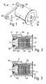
- the mechanism includes a cylindrical barrel 1 having a keyway 2, the barrel being renderable into unlocked and locked modes respectively by insertion and withdrawal of an appropriate key (not shown) from the keyway 2.
- the barrel has a shaft 3 extending axially from one end 5 thereof.
- the shaft 3 has part of a drive in the form of a square drive 7 adjacent the end 5, a land 9 adjacent the square drive 7 and a circlip groove 11 adjacent the land 9.
- a series of tumblers 13 extend, when the barrel is in its locked mode, radially outwardly from a periphery 15 of the barrel on either side thereof.
- the barrel 1 is rotatably mounted in a housing 17 and axially located therein by a flange 19.
- the flange 19 locates in an annular recess 21 in the housing 17.
- rotatable means in the form of a cylindrical sleeve 23.
- the sleeve has a pair of grooves 25 extending internally therealong to receive the tumblers 13 of the barrel 1, the grooves together with the tumblers forming a further drive.
- the sleeve 23 includes part of a cam mechanism in the form of a circular axially extending face cam 27 having four lobes 29 thereon.
- the face cam 27 co-operates with another part of the cam mechanism in the form of a follower 31 having recesses 33, each corresponding to a lobe 29.
- Another part of the drive namely a driven element in the form of an arm 35 has a square drive aperture 37 loosely co-operating with the square drive 7 rotatably to drive, with the required lost motion, the arm 35 upon rotation of the barrel 1 in its unlocked mode.
- the housing 17 has a stop in the form of a leg 39 having a foot 41 on a free end thereof extending towards the barrel axis.
- the foot 41 is positioned to engage a slot 43 in the arm 35 when the arm is positioned on the land 9 of the shaft 3.
- the arm 35 has a small aperture 45 for attachment of the arm to a latch mechanism (not shown).
- a coil spring 49 is interposed between a thrust washer 51 which bears against a circlip 53 located in the circlip groove 11 and the arm 35 resiliently to urge the arm into engagement with the square drive 7.
- FIGs 2 and 3 schematically show the position of the tumblers 13 with the correct key (not shown) inserted into the keyway 2 ( Figure 2) and with no key at all ( Figure 3).
- the tumblers 13 will all be retracted within the barrel periphery 15, the coil spring 49 will be urging the arm 35 into engagement with the square drive 7, and rotation of the barrel 1 by the key will cause rotation of the arm 35 and thereby unlock or lock the latch mechanism, according to the direction in which the barrel is rotated.
- the coil spring 49 will not only urge the arm into engagement with the square drive 7, but will also urge the recesses 33 on the follower 31 of the sleeve 23 into intimate contact with the cam lobes 29 of the face cam 27 and thus prevent rotation of the sleeve 23 during rotation of the barrel while unlocking or locking the latch mechanism.
- Disengagement of the square drive takes place over just a few degrees of rotation of the barrel 1, and the barrel is linked to the latch mechanism sufficiently loosely through the appropriately formed square drive aperture 37 so that lost motion provided by the loose linkage allows disengagement of drive before unlocking or locking of the latch mechanism takes place.
- the barrel 1 and sleeve 23 will be free to rotate through 360° within the housing 17 when the drive is disengaged. If the barrel 1 is left, after an unauthorised attempt to operate the latch, in a position other than as shown in Figure 1, insertion of the correct key and rotation of the barrel to the position of Figure 1 will allow the correspponding cams and recesses to re-engage one another whereupon the coil spring will urge the arm 35 back into engagement with the square drive 7 whilst returning the sleeve to its inoperative position. The arm 35 may then be turned in the desired direction by turning the key in the barrel to unlock or lock the latch mechanism.
Landscapes
- Lock And Its Accessories (AREA)
Claims (12)
- Mécanisme de verrouillage pour verrouiller et déverrouiller un mécanisme de serrure d'une portière, le mécanisme de verrouillage comprenant un boîtier (17) destiné à être fixé sur un véhicule, un barillet (1) pouvant tourner dans le boîtier, un entraînement (7, 37) pouvant être engagé de façon sélective entre le barillet (1) et le mécanisme de serrure de portière, et des moyens (23) permettant de désengager l'entraînement (7, 37), dans lequel le barillet (1) présente un état déverrouillé et un état verrouillé, de telle sorte qu'un mouvement de rotation du barillet, lorsqu'il se trouve à l'état déverrouillé, soit communiqué au mécanisme de serrure de portière par l'intermédiaire de l'entraînement (7, 37), alors que la rotation du barillet (1), lorsqu'il se trouve à l'état verrouillé, actionne les moyens (23) de désengagement de manière à désengager l'entraînement (7, 37).
- Mécanisme de verrouillage selon la revendication 1, dans lequel l'entraînement (7, 37) comprend des éléments menants et menés qui sont coaxiaux par rapport au barillet (1) et sont axialement mobiles les uns par rapport aux autres, de façon sélective, de manière à engager ou à désengager l'entraînement.
- Mécanisme de verrouillage selon la revendication 2, dans lequel les moyens de désengagement comprennent des moyens (23) pouvant tourner avec le barillet (1) lorsqu'il se trouve à l'état verrouillé, lesdits moyens rotatifs produisant ledit mouvement relatif axial entre lesdits éléments de l'entraînement (7, 37) lorsqu'ils sont entraînés en rotation avec le barillet (1).
- Mécanisme de verrouillage selon l'une des revendications 2 ou 3, dans lequel le mouvement relatif axial des éléments de l'entraînement (7, 37) est créé par un mécanisme à cames (27, 31).
- Mécanisme de verrouillage selon la figure 4, dans lequel les moyens rotatifs s'étendent sous forme d'une douille (23) autour du barillet (1), entre le barillet et le boîtier (17), et peuvent être reliés au barillet, lorsque le barillet est à l'état verrouillé, par un entraînement supplémentaire (13, 25) extensible entre une périphérie (15) du barillet (1) et les moyens rotatifs (23).
- Mécanisme de verrouillage selon la revendication 5, dans lequel le mécanisme à cames (27, 31) peut agir entre la douille (23) et le boîtier (17).
- Mécanisme de verrouillage selon la revendication 6, dans lequel l'entraînement (7, 37) ne peut être rembrayé que lorsque le barillet (1) est tourné dans une position prédéterminée.
- Mécanisme de verrouillage selon l'une quelconque des revendications 4 à 7, dans lequel le rembrayage de l'entraînement (7, 37) est autorisé lorsqu'une ou plusieurs cames (29) du mécanisme à cames (27, 31) s'engage(nt) dans des renfoncement conjugués (33) ménagés dans un moyen suiveur de came (31).
- Mécanisme de verrouillage selon l'une quelconque des revendications 2 à 8, dans lequel un arbre (3) s'étend de façon centrale axialement depuis l'une des extrémités du barillet (1) et porte un dit élément menant (7), ledit élément mené (35, 37) étant monté de façon coulissante sur l'arbre (3) en vue d'un engagement sélectif avec l'élément menant (7).
- Mécanisme de verrouillage selon la revendication 9, dans lequel l'élément mené (35, 37) est forcé en direction de l'élément menant (7) par un ressort (49).
- Mécanisme de verrouillage selon l'une quelconque des revendications précédentes, dans lequel une course morte suffisante est admise dans l'entraînement (7, 37), entre le barillet (1) et un mécanisme de serrure d'une portière, pour que l'entraînement puisse être désengagé avant que le mécanisme de serrure ne soit déverrouillé, lorsque le barillet (1) est mis en rotation à l'état verrouillé.
- Mécanisme de verrouillage selon l'une quelconque des revendications 2 à 11, dans lequel des moyens de butée (39, 41) peuvent entrer en engagement avec l'élément mené (35, 37), lorsque l'entraînement est désengagé, de manière à empêcher tout mouvement de l'élément mené (35, 37).
Applications Claiming Priority (2)
| Application Number | Priority Date | Filing Date | Title |
|---|---|---|---|
| GB8904155A GB2228523B (en) | 1989-02-23 | 1989-02-23 | A locking mechanism |
| GB8904155 | 1989-02-23 |
Publications (2)
| Publication Number | Publication Date |
|---|---|
| EP0384648A1 EP0384648A1 (fr) | 1990-08-29 |
| EP0384648B1 true EP0384648B1 (fr) | 1992-12-23 |
Family
ID=10652203
Family Applications (1)
| Application Number | Title | Priority Date | Filing Date |
|---|---|---|---|
| EP90301629A Expired - Lifetime EP0384648B1 (fr) | 1989-02-23 | 1990-02-15 | Mécanisme pour verrouiller |
Country Status (5)
| Country | Link |
|---|---|
| US (1) | US5070716A (fr) |
| EP (1) | EP0384648B1 (fr) |
| JP (1) | JPH02292475A (fr) |
| DE (1) | DE69000624T2 (fr) |
| GB (1) | GB2228523B (fr) |
Families Citing this family (35)
| Publication number | Priority date | Publication date | Assignee | Title |
|---|---|---|---|---|
| SE465473B (sv) * | 1990-01-26 | 1991-09-16 | Ferenc Moricz | Uppbrytningssaekra laas, speciellt foer bilar |
| US5265453A (en) * | 1990-11-30 | 1993-11-30 | Alpha Corporation | Cylinder lock |
| DE4122414C1 (de) * | 1991-07-06 | 1992-12-03 | Huelsbeck & Fuerst | Schließzylinder |
| US5265454A (en) * | 1991-11-19 | 1993-11-30 | Eastern Company | Combined lock and latch |
| US5413392A (en) * | 1993-04-06 | 1995-05-09 | Southco, Inc. | Pawl assembly |
| JPH084378A (ja) * | 1993-11-30 | 1996-01-09 | Tokai Rika Co Ltd | シリンダ錠装置 |
| US5640864A (en) * | 1993-12-27 | 1997-06-24 | Alpha Corporation | Cylinder lock resistible against breaking |
| GB2286222B (en) * | 1994-01-28 | 1997-05-28 | Valeo Security Systems Ltd | Mechanical deadlock |
| DE19604350B4 (de) * | 1995-03-08 | 2005-04-14 | Huf Hülsbeck & Fürst Gmbh & Co. Kg | Verschlußvorrichtung mit einem Schließzylinder für insbesondere an Fahrzeugen vollziehbare Schließfunktionen |
| FR2766512A1 (fr) * | 1997-07-28 | 1999-01-29 | Euro Locks | Serrure a came neutralisable |
| DE19749329C1 (de) * | 1997-11-07 | 1999-07-22 | Huf Huelsbeck & Fuerst Gmbh | Verschlußvorrichtung mit einem schlüsselbetätigbaren Zylinderkern |
| DE19823580C2 (de) * | 1998-05-27 | 2000-12-07 | Kiekert Ag | Schließzylinderaggregat für einen Kraftfahrzeugtürverschluß |
| US5927115A (en) * | 1998-06-10 | 1999-07-27 | Feder; George N. | Pick-resistant lock system and method |
| US6058752A (en) * | 1998-06-10 | 2000-05-09 | Feder; George N. | Pick-resistant lock system and method |
| US6058751A (en) * | 1998-09-08 | 2000-05-09 | Strattec Security Corporation | Free-wheeling lock |
| US6523382B1 (en) | 1998-09-08 | 2003-02-25 | Strattec Security Corporation | Free wheeling lock assembly |
| DE29820711U1 (de) * | 1998-11-19 | 2000-03-30 | Ramsauer Dieter | Drehriegelverschluß mit Zugeinrichtung |
| SE517283C2 (sv) * | 1998-12-10 | 2002-05-21 | Volvo Personvagnar Ab | Anordning vid cylinderlås |
| GB2350146A (en) * | 1999-05-13 | 2000-11-22 | Rover Group | Motor vehicle lock assembly |
| US6564603B1 (en) * | 2002-05-02 | 2003-05-20 | O'neill Louis | Security cam for a cylinder lock |
| US6711924B2 (en) * | 2002-06-18 | 2004-03-30 | Strattec Security Corporation | Freewheeling lock apparatus and method |
| US8347678B2 (en) * | 2002-09-26 | 2013-01-08 | Newfrey, Llc | Rekeyable lock cylinder assembly |
| US6978645B2 (en) * | 2003-06-23 | 2005-12-27 | Strattec Security Corporation | Freewheeling lock apparatus and method |
| US20050115288A1 (en) * | 2003-12-02 | 2005-06-02 | Burmahln Jedediah A. | Adjustable locking mechanism |
| DE102007023458A1 (de) * | 2007-05-19 | 2008-11-20 | Huf Hülsbeck & Fürst Gmbh & Co. Kg | Schließzylinder für insbesondere in einem Fahrzeug ausführbare Funktionen |
| CN101196085B (zh) * | 2007-12-13 | 2012-02-01 | 朱长洛 | 弹片式防盗锁 |
| US8276416B2 (en) * | 2009-02-18 | 2012-10-02 | Vsi, Llc | Master key lock, system and method |
| JP5739885B2 (ja) * | 2009-07-24 | 2015-06-24 | 平頂山市大漢鎖業有限公司 | 連動式防犯シリンダー錠 |
| US8099988B1 (en) * | 2010-08-09 | 2012-01-24 | Newfrey, Llc | Tool-less rekeyable lock cylinder |
| US8291735B1 (en) | 2011-03-31 | 2012-10-23 | Newfrey, Llc | Rekeyable lock cylinder having rotatable key followers |
| JP6074812B2 (ja) * | 2013-12-13 | 2017-02-08 | 株式会社ホンダロック | シリンダ錠装置 |
| US20150211257A1 (en) * | 2014-01-28 | 2015-07-30 | Vsi, Llc | Free-wheel lock and assembly |
| TWM521102U (zh) * | 2015-08-28 | 2016-05-01 | Lintex Co Ltd | 鎖具 |
| US11319726B2 (en) | 2018-10-22 | 2022-05-03 | Spectrum Brands, Inc. | Tool-less rekeyable lock cylinder |
| CN110388136B (zh) * | 2019-08-29 | 2024-05-10 | 深圳市弘博汇科技有限公司 | 丝杆拨块驱动式锁结构 |
Family Cites Families (14)
| Publication number | Priority date | Publication date | Assignee | Title |
|---|---|---|---|---|
| US2096719A (en) * | 1933-10-30 | 1937-10-26 | Theodore H Johnstone | Lock |
| US2068405A (en) * | 1933-12-11 | 1937-01-19 | Briggs & Stratton Corp | Lock |
| US2016602A (en) * | 1934-06-11 | 1935-10-08 | Briggs & Stratton Corp | Lock |
| US3524335A (en) * | 1968-02-06 | 1970-08-18 | Harry F George | Axial tumbler type lock and key therefor |
| FR1595968A (fr) * | 1968-12-06 | 1970-06-15 | ||
| US4008588A (en) * | 1976-04-28 | 1977-02-22 | H. Edward Tickel, Jr. | Rotary plug cylinder lock construction |
| GB1557208A (en) * | 1977-04-28 | 1979-12-05 | Pinson Ltd Enoch | Locking device |
| GB2005335B (en) * | 1977-09-08 | 1982-02-03 | Willenhall Ltd L & F | Lock |
| CA1158452A (fr) * | 1979-03-16 | 1983-12-13 | Barrie S. Harper | Verrou a barillet(s) |
| US4369642A (en) * | 1981-03-25 | 1983-01-25 | Norris Industries, Inc. | Detained key assembly |
| GB2165295B (en) * | 1984-10-04 | 1987-09-23 | Ford Motor Co | A lock assembly |
| US4773240A (en) * | 1986-10-20 | 1988-09-27 | Best Lock Corporation | Lock with force-override assembly |
| US4794772A (en) * | 1988-03-10 | 1989-01-03 | K.X.L. Manufacturing, Inc. | Axial wafer tumbler lock and key |
| FR2631067B1 (fr) * | 1988-05-04 | 1991-02-08 | Neiman Sa | Verrou a rotor debrayable |
-
1989
- 1989-02-23 GB GB8904155A patent/GB2228523B/en not_active Revoked
-
1990
- 1990-02-08 US US07/477,237 patent/US5070716A/en not_active Expired - Lifetime
- 1990-02-15 EP EP90301629A patent/EP0384648B1/fr not_active Expired - Lifetime
- 1990-02-15 DE DE9090301629T patent/DE69000624T2/de not_active Expired - Fee Related
- 1990-02-23 JP JP2041352A patent/JPH02292475A/ja active Pending
Also Published As
| Publication number | Publication date |
|---|---|
| GB2228523B (en) | 1993-04-14 |
| US5070716A (en) | 1991-12-10 |
| DE69000624D1 (en) | 1993-02-04 |
| EP0384648A1 (fr) | 1990-08-29 |
| GB8904155D0 (en) | 1989-04-05 |
| DE69000624T2 (de) | 1993-04-22 |
| JPH02292475A (ja) | 1990-12-03 |
| GB2228523A (en) | 1990-08-29 |
Similar Documents
| Publication | Publication Date | Title |
|---|---|---|
| EP0384648B1 (fr) | Mécanisme pour verrouiller | |
| US4394821A (en) | Door lock mechanism | |
| US5265453A (en) | Cylinder lock | |
| EP0675248B1 (fr) | Dispositif de serrure cylindrique résistant au déverrouillage non autorisé | |
| US6354117B1 (en) | Steering column anti-theft device for motor vehicle | |
| US7007525B2 (en) | Electric steering lock device | |
| US4512166A (en) | Cylinder lock and key | |
| US5285667A (en) | Cylinder lock | |
| US6003349A (en) | Vehicle lock device | |
| US4426864A (en) | Cylinder lock | |
| WO2005086745A2 (fr) | Barillet de serrure universel | |
| US3442102A (en) | Cylinder lock actuator | |
| JPS5854279Y2 (ja) | 車輌のステアリングロツク装置 | |
| EP0978608A1 (fr) | Mecanisme de serrure a cylindre | |
| US7339472B2 (en) | Self-adjusting cam assembly | |
| JP2707347B2 (ja) | 施錠装置 | |
| EP0037399B1 (fr) | Serrures | |
| EP0488787B1 (fr) | Serrure cylindrique | |
| GB2298229A (en) | A lock | |
| US3938359A (en) | Lock assembly | |
| CN211229837U (zh) | 保险锁舌的伸出与回位机构 | |
| JP2906186B2 (ja) | シリンダ錠 | |
| CA2503683C (fr) | Came autoreglable | |
| US3302430A (en) | Coupling | |
| KR200188541Y1 (ko) | 실린더 자물쇠 |
Legal Events
| Date | Code | Title | Description |
|---|---|---|---|
| PUAI | Public reference made under article 153(3) epc to a published international application that has entered the european phase |
Free format text: ORIGINAL CODE: 0009012 |
|
| AK | Designated contracting states |
Kind code of ref document: A1 Designated state(s): DE ES FR GB IT NL |
|
| 17P | Request for examination filed |
Effective date: 19901219 |
|
| 17Q | First examination report despatched |
Effective date: 19920409 |
|
| GRAA | (expected) grant |
Free format text: ORIGINAL CODE: 0009210 |
|
| AK | Designated contracting states |
Kind code of ref document: B1 Designated state(s): DE ES FR GB IT NL |
|
| PG25 | Lapsed in a contracting state [announced via postgrant information from national office to epo] |
Ref country code: IT Free format text: LAPSE BECAUSE OF FAILURE TO SUBMIT A TRANSLATION OF THE DESCRIPTION OR TO PAY THE FEE WITHIN THE PRE;WARNING: LAPSES OF ITALIAN PATENTS WITH EFFECTIVE DATE BEFORE 2007 MAY HAVE OCCURRED AT ANY TIME BEFORE 2007. THE CORRECT EFFECTIVE DATE MAY BE DIFFERENT FROM THE ONE RECORDED.SCRIBED TIME-LIMIT Effective date: 19921223 Ref country code: ES Free format text: THE PATENT HAS BEEN ANNULLED BY A DECISION OF A NATIONAL AUTHORITY Effective date: 19921223 Ref country code: NL Effective date: 19921223 |
|
| REF | Corresponds to: |
Ref document number: 69000624 Country of ref document: DE Date of ref document: 19930204 |
|
| ET | Fr: translation filed | ||
| NLV1 | Nl: lapsed or annulled due to failure to fulfill the requirements of art. 29p and 29m of the patents act | ||
| PLBE | No opposition filed within time limit |
Free format text: ORIGINAL CODE: 0009261 |
|
| STAA | Information on the status of an ep patent application or granted ep patent |
Free format text: STATUS: NO OPPOSITION FILED WITHIN TIME LIMIT |
|
| 26N | No opposition filed | ||
| REG | Reference to a national code |
Ref country code: FR Ref legal event code: CA |
|
| REG | Reference to a national code |
Ref country code: GB Ref legal event code: 732E |
|
| REG | Reference to a national code |
Ref country code: GB Ref legal event code: IF02 |
|
| PGFP | Annual fee paid to national office [announced via postgrant information from national office to epo] |
Ref country code: GB Payment date: 20070301 Year of fee payment: 18 |
|
| PGFP | Annual fee paid to national office [announced via postgrant information from national office to epo] |
Ref country code: DE Payment date: 20070330 Year of fee payment: 18 |
|
| PGFP | Annual fee paid to national office [announced via postgrant information from national office to epo] |
Ref country code: FR Payment date: 20070226 Year of fee payment: 18 |
|
| GBPC | Gb: european patent ceased through non-payment of renewal fee |
Effective date: 20080215 |
|
| REG | Reference to a national code |
Ref country code: FR Ref legal event code: ST Effective date: 20081031 |
|
| PG25 | Lapsed in a contracting state [announced via postgrant information from national office to epo] |
Ref country code: DE Free format text: LAPSE BECAUSE OF NON-PAYMENT OF DUE FEES Effective date: 20080902 |
|
| PG25 | Lapsed in a contracting state [announced via postgrant information from national office to epo] |
Ref country code: FR Free format text: LAPSE BECAUSE OF NON-PAYMENT OF DUE FEES Effective date: 20080229 |
|
| PG25 | Lapsed in a contracting state [announced via postgrant information from national office to epo] |
Ref country code: GB Free format text: LAPSE BECAUSE OF NON-PAYMENT OF DUE FEES Effective date: 20080215 |