EP0384105A1 - Track guidance device for tyred vehicles - Google Patents
Track guidance device for tyred vehicles Download PDFInfo
- Publication number
- EP0384105A1 EP0384105A1 EP90100256A EP90100256A EP0384105A1 EP 0384105 A1 EP0384105 A1 EP 0384105A1 EP 90100256 A EP90100256 A EP 90100256A EP 90100256 A EP90100256 A EP 90100256A EP 0384105 A1 EP0384105 A1 EP 0384105A1
- Authority
- EP
- European Patent Office
- Prior art keywords
- pressure
- piston
- steering
- guide rail
- tracking
- Prior art date
- Legal status (The legal status is an assumption and is not a legal conclusion. Google has not performed a legal analysis and makes no representation as to the accuracy of the status listed.)
- Withdrawn
Links
Images


Classifications
-
- B—PERFORMING OPERATIONS; TRANSPORTING
- B62—LAND VEHICLES FOR TRAVELLING OTHERWISE THAN ON RAILS
- B62D—MOTOR VEHICLES; TRAILERS
- B62D7/00—Steering linkage; Stub axles or their mountings
- B62D7/06—Steering linkage; Stub axles or their mountings for individually-pivoted wheels, e.g. on king-pins
- B62D7/14—Steering linkage; Stub axles or their mountings for individually-pivoted wheels, e.g. on king-pins the pivotal axes being situated in more than one plane transverse to the longitudinal centre line of the vehicle, e.g. all-wheel steering
- B62D7/15—Steering linkage; Stub axles or their mountings for individually-pivoted wheels, e.g. on king-pins the pivotal axes being situated in more than one plane transverse to the longitudinal centre line of the vehicle, e.g. all-wheel steering characterised by means varying the ratio between the steering angles of the steered wheels
- B62D7/1554—Steering linkage; Stub axles or their mountings for individually-pivoted wheels, e.g. on king-pins the pivotal axes being situated in more than one plane transverse to the longitudinal centre line of the vehicle, e.g. all-wheel steering characterised by means varying the ratio between the steering angles of the steered wheels comprising a fluid interconnecting system between the steering control means of the different axles
- B62D7/1572—Steering linkage; Stub axles or their mountings for individually-pivoted wheels, e.g. on king-pins the pivotal axes being situated in more than one plane transverse to the longitudinal centre line of the vehicle, e.g. all-wheel steering characterised by means varying the ratio between the steering angles of the steered wheels comprising a fluid interconnecting system between the steering control means of the different axles provided with electro-hydraulic control means
-
- B—PERFORMING OPERATIONS; TRANSPORTING
- B62—LAND VEHICLES FOR TRAVELLING OTHERWISE THAN ON RAILS
- B62D—MOTOR VEHICLES; TRAILERS
- B62D1/00—Steering controls, i.e. means for initiating a change of direction of the vehicle
- B62D1/24—Steering controls, i.e. means for initiating a change of direction of the vehicle not vehicle-mounted
- B62D1/26—Steering controls, i.e. means for initiating a change of direction of the vehicle not vehicle-mounted mechanical, e.g. by a non-load-bearing guide
- B62D1/265—Steering controls, i.e. means for initiating a change of direction of the vehicle not vehicle-mounted mechanical, e.g. by a non-load-bearing guide especially adapted for guiding road vehicles carrying loads or passengers, e.g. in urban networks for public transportation
-
- B—PERFORMING OPERATIONS; TRANSPORTING
- B62—LAND VEHICLES FOR TRAVELLING OTHERWISE THAN ON RAILS
- B62D—MOTOR VEHICLES; TRAILERS
- B62D7/00—Steering linkage; Stub axles or their mountings
- B62D7/06—Steering linkage; Stub axles or their mountings for individually-pivoted wheels, e.g. on king-pins
- B62D7/14—Steering linkage; Stub axles or their mountings for individually-pivoted wheels, e.g. on king-pins the pivotal axes being situated in more than one plane transverse to the longitudinal centre line of the vehicle, e.g. all-wheel steering
- B62D7/15—Steering linkage; Stub axles or their mountings for individually-pivoted wheels, e.g. on king-pins the pivotal axes being situated in more than one plane transverse to the longitudinal centre line of the vehicle, e.g. all-wheel steering characterised by means varying the ratio between the steering angles of the steered wheels
- B62D7/1518—Steering linkage; Stub axles or their mountings for individually-pivoted wheels, e.g. on king-pins the pivotal axes being situated in more than one plane transverse to the longitudinal centre line of the vehicle, e.g. all-wheel steering characterised by means varying the ratio between the steering angles of the steered wheels comprising a mechanical interconnecting system between the steering control means of the different axles
- B62D7/1536—Steering linkage; Stub axles or their mountings for individually-pivoted wheels, e.g. on king-pins the pivotal axes being situated in more than one plane transverse to the longitudinal centre line of the vehicle, e.g. all-wheel steering characterised by means varying the ratio between the steering angles of the steered wheels comprising a mechanical interconnecting system between the steering control means of the different axles provided with hydraulic assistance
Definitions
- the invention relates to track guidance devices for a track guidance rail that can be guided on one side along a route along a defined width by gaps by means of feeler rollers, rubber-tired vehicle that can be operated in both directions - forwards, backwards - with comparable conditions and has a steered front and rear axle.
- Such a lane guidance is a special case, which is due to the character and operational characteristics of the vehicle.
- the problem with such guidance systems does not regularly arise that the guidance guidance rail has gaps that should be passed. Only continuous guardrails are used in bus guidance operation.
- the measures in accordance with sub-characteristic a) create the prerequisite for the fact that gage guide rails with gaps can be used as a guiding element.
- the measures or devices according to features b) and c) ensure that the vehicle is guided exactly along the route both in the area of the front and rear axles in the direction of travel, it being possible to effectively prevent gaps in the area of the guidance guide rail Misguided states occur.
- the invention is concerned with guiding rubber-tired vehicles in both directions (forward, backward) on a roadway (route) safely and precisely along a guidance guide rail which has interruptions of a certain length and can be laid on both the right and left-hand side of the roadway , for example also in such a way that the vehicles can encounter one another on the same lane and a small safety distance can be maintained when the vehicles pass each other.
- the said vehicles come e.g. as special buses or other special vehicles, in airports, high-bay warehouses, large manufacturing factories, container transshipment points, in tunnels or the like, for freight transport, service, rescue or similar services.
- the track guidance rails are interrupted at intervals that are greater than the vehicle length by Lükken due to branching cross roads, cross tunnels, alleys and the like.
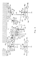
- FIG. 1 shows, as an example of a lane guidance case, a lane 3 having two lanes 1, 2 with lane guidance rails 4, 5 running on both sides along the same.
- Vehicles 6 can be guided exactly along these guiding guide rails 4, 5 by means of guiding devices provided on them.
- This guidance is so precise that in the encountered guidance operation shown a minimum distance of 10 to 20 cm, denoted by 7 in FIG. 1, between the vehicles 6 can be maintained in spite of the negative pressure zones created by the latter in front of the latter or in the rear area.
- the gaps interrupting the guidance guide rail 4 or 5, resulting from cross streets, cross tunnels, alleys or the like, are designated 8 and 9 in the figures (as far as shown).
- the vehicles used are, for example, those which, as can be seen in FIG. 2, have a driver's cab 10 and 11 at the front and rear with a loading or carrying area 12 and a drive device which operate the vehicle 6 in both directions (forward, backward) under the same drive conditions.
- a driver's cab 10 and 11 at the front and rear with a loading or carrying area 12 and a drive device which operate the vehicle 6 in both directions (forward, backward) under the same drive conditions.
- the vehicles 6 have front and rear axles 13 and 14 with steerable wheels 15, 16 and 17, 18, respectively, with their schematically indicated steering knuckles 15 'or 16' or 17 'or 18' about an associated pivot axis 15 ⁇ or 16 ⁇ or 17 ⁇ or 18 ⁇ are pivotable.
- a conventional steering linkage 19 or 20 is articulated to each steering knuckle, which is connected in a gearbox manner, not shown, to the steering wheel which can be handled by the driver in the respectively assigned driver's cab 10 or 11.
- the steering levers 19 'and 19 ⁇ are each firmly connected to the associated steering knuckles 15' or 16 'or 17' or 18 '.
- a tracking device which serves to drive a vehicle 6 during the tracking operation are described in detail below to guide itself automatically in the area of the front axle 13 as well as the rear axle 14 safely along a guidance guide rail 4 or 5, but if necessary also to ensure a rapid lane change with secure positioning on the opposite guidance guide rail 5 or 4.
- the tracking device is generally constructed in such a way that all necessary driving maneuvers can be carried out at any time with the vehicle 6 detached from the tracking guide rail 4, 5.
- Each steered wheel 15, 16, 17, 18 is basically assigned a pair of feeler rollers 15a, 15b or 16a, 16b or 17a, 17b or 18a, 18b.
- These two tracer rollers of a pair of tracer rollers, identified by index a, b, are spaced apart from one another on the vehicle in the longitudinal direction by an amount that is somewhat larger than the width of a gap 8 or 9 in the guiding guide rail 4 or 5 in the region of a Cross alley or the like.
- the arrangement of the two sensing rollers marked with index a, b is such that they protrude the outside of the associated wheel 15 or 16 or 17 or 18 by a small amount of, for example, 5 centimeters.
- the two tracer rollers of a pair of tracer rollers can, as can be seen from FIGS. 3, 4, 6, 7, 9 and 10, in front of and behind the associated wheel 15 or 16 or 17 or 18, or - as shown in FIG.
- the probe rollers 15a, 16a, 17b, 18b which are spaced further apart from the associated wheel, are mounted on probe arms, each of which with which the respectively adjacent one Tracer roller of the tracer arm pair carrying tracer arm is firmly connected and has a telescopic piston cylinder, which makes it possible to retract the tracer roller arranged on it when it is not needed, for example, when driving not on a track.
- the connecting rod 21 consists of two aligned straight rods 21a, 21b, which is a preferably diagonal connection between a joint 15 ′′′, which is at the outer end of a steering knuckle 15 'of the wheel 15th given lever is arranged, and forms a joint 18 ′′′, which is arranged at the outer end of a fixed to the steering knuckle 18 'of the wheel 18 given lever.
- the two rods 21a, 21b are equipped at their mutually facing ends with pistons 21c, 21d separating two pressure chambers 22a, 22b and 23a, 23b from each other within hydraulic pressure cylinders 22, 23.
- These pistons 21c, 21d with their pressure cylinders 22, 23 are part of a device for changing the effective length of the Linkage 21.
- This device further consists of a hydraulic control block 24, connecting lines 25, 26, 27, 28 between the latter and the pressure chambers 22a, 22b, 23a, 23b, and a pressure medium supply device 29.
- the pressure chambers 22a and 22b on the one hand and 23a and 23b on the other hand can be deliberately pressure-relieved or relieved to the storage tank 30 by the control block 24 in such a way that a desired extension or shortening of the connecting rod 21 results.
- These loading and unloading processes are then controlled, with the pressure rooms then being shut off, by appropriate commands which are automatically controlled by an electronic regulating and control device 31 as a function of conditions to be explained in more detail further below or by an encoder mechanism on the control block 24 which can be actuated by the driver in the respective driver's cab be delivered.
- This device for changing the length of the connecting rod 21 thus serves to steer the steering kinematics of the wheels 15, 16, 17, 18 of the two steered axles 13, 14 to the conditions of the route for straight-ahead or cornering, or changing driving situations, for example a necessary lane change To adjust the parallel offset in such a way that the vehicle 6 is guided in the region of both axles 13, 14 to the tracking guide rail 4 or 5 to be scanned.
- both pistons 21 c, 21 d in their respective pressure cylinders 22 and 23 are in the middle of the stroke distance between two stops and are hydraulically blocked in this position, then the connecting linkage 21; 21a, 21b that length in which the wheels 15, 16, 17, 18 of both axles 13, 14 are set so that the vehicle 6 runs exactly straight. If the connecting linkage remains blocked in this "zero position", the axles 13, 14 would obey the known conditions of all-wheel steering with each steering movement of the front wheels as seen in the direction of travel, ie, for example, the wheel 15 is deflected away from the guide rail 4 , then the wheel 17 is steered towards the guidance guide rail with an angular steering lock.
- the effective length of the connecting linkage 21, 21a, 21b must be changed, ie extended or shortened.
- maximum extension or maximum shortening of the linkage 21; 21a, 21b the case can be brought about that the wheels 15, 16 of one axle 13 are driven in the same direction and at the same angle as the wheels 17, 18 of the other axle 14.
- This parallel pivoting of the wheels also known as a pass gear particularly desirable when a vehicle 6 should or must make a rapid lane change, ie, steered away from the one guidance guide rail 4, for example, and then must or must be continued on the opposite guidance guide rail 5.
- the effective length of the connecting linkage 21; 21a, 21b can also be extended or shortened by a correspondingly large amount.
- This goal can be achieved by means of piston / pressure cylinder units 21c, 22 or 21d, 23 designed to be very long stroke. If these long piston / pressure cylinder units are not feasible, one can make use of the fact that, as can be seen in FIG. 4, means are built into one of the rods 21a or 21b, which means that the steering movements of the wheels of both axles 13, 14 make adjustable. This means that you can choose between the settings for all-wheel steering and Padedgang- or parallel steering and for non-steering of the second axle.
- the rod 21b is divided into two parts 21b ', 21b ⁇ , both of which are articulated on a rocker arm link 32, namely the rod part 21b' in one end of the rocker arm link 32 given swivel 33 and the other rod part 21b ⁇ with a sliding block or a sliding block 34 in a slot 35, which extends along the swing arm link 32 which is articulated on a chassis-fixed bearing 36 and which is pivotable approximately in the middle of its longitudinal extension.
- an adjustment device here in the form of a piston / pressure cylinder unit, engages on the rod part 21b ⁇ , one end being fixed to the chassis, the other articulatedly connected to the rod part 21b ⁇ , the piston 37 in the pressure cylinder 38 separating two pressure spaces 39, 40 from one another, which are connected to a hydraulic control unit for targeted loading and unloading or shut-off via pressure lines 41, 42.
- the latter can be combined with the control block 24 Unit be united. If the sliding block 34 is in the position shown in FIG. 4, then the same conditions as in the case according to FIG. 3 result with appropriately selected lever lengths.
- the connecting linkage has 21; 21a, 21b ′, 21b ⁇ , 32 the properties of parallel steering. If the sliding block 34 is located exactly above the fulcrum 36 of the rocker arm link 32, then the rod part 21bfest is blocked with the frame, in which case changes in the states of the piston / pressure cylinder units 21c, 22 or 21d, 23 are merely changes cause in the steering kinematics of the wheels 15, 16 of the axle 13.
- Another component of the tracking device is a device for generating a defined steering torque with which the steered wheels 15, 16, 17, 18 of the two axles 13, 14 are directed toward the tracking guide rails 4 and 5 respectively used for guidance.
- a device is constructed, for example, as that known from EP 0 111 258, which was used there in connection with the guidance of an omnibus.
- Said device consists of a piston / pressure cylinder unit, with a pressure cylinder 43 and a piston 46 separating two pressure chambers 44, 45 from one another in the latter, one of the two parts 43, 46 on a bearing 47 fixed to the frame and the other of the two parts 43, 46 is articulated to a bearing 48 which is fixed in terms of movement to one of the four steering knuckles 15 'or 16' or 17 'or 18' arranged or articulated organ 48 ', such as levers, pillars or the like, is given.
- Each of the two pressure chambers 44, 45 can be pressure-relieved and relieved in a targeted manner by an electro-hydraulic control device 51 via pressure lines 49, 50 in order to produce the desired contact pressure of the feeler rollers on the guide rail as soon as there is contact with the system.
- the control device 51 is also connected to a pressure medium supply, in particular to the same (29) as the control block 24, and to the supply tank 30 for pressure relief.
- the control device 51 can receive its control commands from the driver through a device which is given in the driver's cab 10, 11 or can be operated and monitored from there;
- the control device 51 preferably also receives its control commands from the electronic regulating and control direction 31.
- the contact pressure for the feeler rollers which is a measure of the steering torque applied, can in the simplest case be set to a fixed value.
- the control according to FIG. 6 is more complex in terms of control technology.
- sensors for example strain gauges 52
- strain gauges 52 are arranged on a region that is favorable or sensitive for the measurement value acquisition, for example strain gauges 52, which Detect the load acting in the respective probe arm and report it to the electronic regulating and control device 31 via signal lines (not shown).
- a speed sensor can be provided on each sensing roller, which speed sensors recognize the states “role in or out of scanning contact with tracking guide rail” by the detected speed and also report them to the electronic regulating and control device 31.
- each sensing roller 15a, 15b; 16a, 16b, 17a, 17b, 18a, 18b are assigned a distance sensor 53 which is arranged adjacent to this and is fixed to the vehicle and which distance sensors are also connected to the electronic regulating and control device 31 via signal lines (not shown).
- These distance sensors 53 are mainly used to detect and report the passage of a gap 8 or 9 in the guide rail 4 or 5, so that when passing through such an area the steering is not readjusted and the control of the contact pressure or the steering torque only resumes when the feeler roller in question has come into contact with the subsequent part of the track guide rail 4 or 5.
- the electronic regulating and control device 31 is preferably constructed as a computer system with the usual hardware, consisting of input and output units, measuring signal converter stages, measuring signal processing stages, program memory, data or working memory, output signal amplifier stages and a central microprocessor (CPU), which assemblies via the usual Data transmission paths (BUS systems) are linked together.
- CPU central microprocessor
- the regulation can, for example, be such that the contact pressure of the sensing rollers increases with increasing vehicle speed and / or when two vehicles have to drive past one another in oncoming traffic.
- the control data required for this are stored in the data or working memory. This data is processed together with the actual operating status values reported by sensors 52, 53 and other sensors such as speed sensors, dynamic pressure measuring sensors and the like sensors by means of a program stored in the program memory.
- control commands are issued via electronic command lines from the electronic regulating and control device 31 to the connected devices, namely the control block 24 and the control device 51, with which the necessary control movements for the adjustment of the respectively guided wheel are then triggered, the execution of which via a Corresponding pressurization of the piston / pressure cylinder unit 43, 46 and / or piston / pressure cylinder units 21c, 22 or 21d, 23 and / or the piston / pressure cylinder unit 37, 38 takes place.
- a lane change is to be carried out, this is triggered by the driver or a command transmitter let into the lane, for example, and transmitted to the electronic regulating and control device 31.
- This then causes the abolition of the contact pressure control, the detachment of the vehicle 6 from the previous guiding rail, the setting of the wheels 15, 16, 17, 18 in the same direction (fitting) via the aforementioned piston / cylinder units 21c, 22 or 21d, 23 or 37, 38, and then, after first contacting the first sensing roller on the opposite tracking guide rail a targeted delivery of the vehicle 6 in relation to the latter both in terms of position and force with appropriate command to the organs generating the contact pressure or the steering torque.
- the two probe arms 15c, 15d or 16c, 16d or 17c, 17d or 18c, 18d for each wheel 15 or 16 or 17 or 18 are not arranged directly but only indirectly on the respective steering knuckle, also designed in the manner of an angle lever.
- one arm part extends in the direction of travel in front of or behind the wheel to be steered perpendicularly or obliquely to the guide rail 4 or 5, while the other arm part, angled to this end, engages behind the wheel behind the steering knuckle 15 'or 16 'Or 17' or 18 'the same spaced from these and extending approximately transversely to the wheel axis and extending so that a certain distance to the adjacent arm part of the other probe arm is given.
- Each of the two probe arms 15c, 15d or 16c, 16d or 17c, 17d or 18c, 18d provided for each wheel is movable at its inner end on a joint 15e, 15f or 16e, 16f on the chassis side or 17e, 17f or 18e, 18f and also articulated in the region of its angled inner arm part by a connecting lever 54 to the adjacent arm part of the other probe arm. This ensures that in each case a correct steering sign movement is brought about on the associated wheel.
- the connection between the two probe arms per wheel and the associated steering knuckles 15 'or 16' or 17 'or 18' is made by piston / pressure cylinder units 55 or 56, which are approximately parallel to the wheel axis between the steering knuckle and Associated, the arm engaging behind the wheel of the probe arm, the one unit seen in the direction of travel before the pivot point 15 ⁇ or 16 ⁇ or 17 ⁇ or 18 ⁇ of the steering knuckle and the other articulated behind this end.
- These piston / pressure cylinder units 55, 56 allow a rigid, blocked connection of the steering knuckle to the connected probe arm or a free movement of the steering knuckle relative to the probe arm.
- the piston / pressure cylinder unit 55 is hydraulically locked, while the piston / pressure cylinder unit 56 remains freely movable. Seen in the direction of travel according to arrow II, the piston / pressure cylinder unit 56 is hydraulically locked, while the piston / pressure cylinder unit 55 is freely movable.
- the blocking or release takes place via an assigned solenoid valve, which is connected to the hydraulic pressure medium supply 29, and a hydraulic bypass, which connects the two chambers on either side of the piston of a piston / pressure cylinder unit in the pressure cylinder, for "blocking""shut off or for "Activation" keeps open.
- the eight solenoid valves can receive their control commands from the electronic regulating and control device 31. In the case according to FIG.
- the latter also controls an electro-hydraulic control block 51, to which the further hydraulic parts of the device for generating the defined steering torque are connected for each axle 13 or 14.
- These parts are piston / pressure cylinder units 43, 46 which, in this example, are designed in the same way as those according to the examples from FIGS. 3 to 6 and are also functionally assigned to the respective wheel steering, ie, for example, themselves extend between a frame-fixed bearing 47 and a bearing 48, which is given on a lever 48 'which is connected to a steering knuckle of a wheel of the front and rear axles 13 and 14, respectively.
- piston / pressure cylinder units 55, 56 instead of the piston / pressure cylinder units 55, 56, other functionally equivalent mechanisms, e.g. lockable or releasable lever mechanisms can be provided.
- the functional coordination for guiding the wheels of both axles 13, 14 to the guide rail 4 or 5 or for guiding the wheels away from the latter, for example for changing lanes, is performed by the electronic regulating and control device 31 by issuing control commands to the Device 51 and said solenoid valves, and their implementation in corresponding individual setting commands for the two piston / pressure cylinder units 43, 46 and the eight piston / pressure cylinder units 55, 56 regulated.
- the end result also results in a tracking control as described above with reference to FIGS. 3 to 6.
- FIG. 9 A mechanically much less complex solution, which is designed with a view to being very robust, is shown in FIG. 9.
- probe arms are dispensed with.
- the feeler rollers 15a, 15b; 16a, 16b; 17a, 17b; 18a, 18b are mounted in front of and behind the respective associated wheel 15, 16, 17, 18 in a fixed position on the frame or body of the vehicle, one behind the other at a distance that is greater than the width of the gap 8 or 9 in the guidance control system 4 or 5, and with only a relatively small projection beyond the lateral contour of the vehicle 6.
- Sensors 57 for example pressure sockets or resolvers, are assigned to these fixedly mounted feeler rollers, which determine the contact of the feeler rollers with the activated tracking guide rail 4 or 5 and report them to the electronic regulating and control device 31 via signal lines.
- This regulating and control device 31 is similar in structure and mode of operation to that of the examples described above; it gives the electrohydraulic control device 51 commands for such a hydraulic actuation of the device for generating a defined steering torque (control device 51, pressure cylinder 43 with pressure chambers 44, 45 and piston 46 between) when a contact contact with the feeler rollers / tracking guide rail 4 or 5 has been determined frame-fixed bearing 47 and bearing 48 on the steering linkage 19) from that the wheels 15, 16, 17, 18 are generally not parallel to the track guide rail 4 or 5, but at a small angle of, for example, 1 - 2 ° to the latter and for Stay in tracking mode (see the slight inclination of the wheels in Fig. 9). This ensures that the tracing rollers always remain in contact with the
- This automatic tracking operation can be switched off or interrupted by the driver, e.g. if the lane is to be changed and the opposite guidance guidance wall is to be activated as a guidance organ.
- the control of the vehicle 6 desired by the driver via the steering wheel movement is detected by sensors and reported to the regulating and control device 31, which then controls the wheels of the rear axle seen in the direction of travel by issuing corresponding control commands via the control device 51 to the associated piston-pressure cylinder unit 43, 44, 46 regulates.
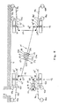
- FIG. 10 A similar simple solution, which also does not require probe arms and does not require a permanent inclination of the wheels to the scanned track guide rail 4 or 5, is shown in FIG. 10.
- the feeler rollers 15a, 15b; 16a, 16b; 17a, 17b; 18a, 18b are rotatably mounted on piston rods 58 which are movable transversely to the direction of travel and substantially perpendicular to the tracking guide rails 4 and 5 to be scanned, which each loaded by a compression spring 59 in the vehicle and permanently in the opposite direction via a connected pressure piston 60 with a pressure provided in a pressure chamber 61 certain, constant size is applied.
- Each pressure piston 60 acts in a pressure cylinder 62 which also includes the associated pressure chamber 61 and which is fixed in a articulated manner on the frame or the body of the vehicle 6.
- the two sensing rollers designated by indices a and b per wheel 15, 16, 17, 18 are hydraulically blocked to the same degree in every position by means of a special electrohydraulic control device, that is to say each sensing roller a is one
- the sensing roller pair a / b is always pressurized with the same hydraulic pressure as the other (b), irrespective of the force with which the sensing rollers are pressed against the tracking guide rail 4 or 5 to be scanned.
- the relevant control device comprises two 4/2-way switching valves 63, 64 or 65, 66 for each steered axle 13 or 14 and also two piston-pressure cylinder units 67, 68 or 69, 70 for each axle 13 or 14 Which above-mentioned components are connected to one another in a special way via pressure lines and to the pressure chambers 61 in the pressure cylinders 62 of the sensing rollers.
- An electro-hydraulic control block 91 is provided on the outlet side for the basic filling of these line paths with oil, for pressure regulation in these and the connected pressure chambers and for oil recharging to compensate for any leakage losses (if necessary) and the oil supply device (pump 29) is connected on the inlet side.
- a pressure switch 92 is assigned to each of the eight switching paths for pressure regulation and monitoring. These pressure monitors 92 report the detected pressure measurement signals to the electronic regulating and control device 31, which, if necessary, activates a corresponding switching element in the control block 91 for the necessary oil quantity and / or oil pressure readjustment in the relevant switching path / pressure chamber.
- a device for generating a defined steering torque, with which the steered wheels 15, 16, 17, 18 of the two axles 13 and 14 are steered toward the guiding guide rails 4 and 5 to be scanned.
- This consists of two piston-pressure cylinder units, one for each axle 13 or 14.
- Each of these consists of a pressure cylinder 43 and a piston 46 separating two pressure chambers 44, 45 in the latter and is one end on a chassis or body-fixed bearing point 47 and another articulated on a steering linkage 19 or 20 or other organs which effect the steering of the wheels per axle 13 or 14.
- the two pressure chambers 44, 45 per piston-pressure cylinder unit 43, 46 are connected via pressure lines 49, 50 to the electro-hydraulic control block 51, which is controlled by commands from the electronic regulating and control device 31 for a corresponding pressure relief or relief of the pressure chambers 44, 45, the contact pressure of the feeler rollers being adjusted and readjusted accordingly.
- This lane guidance operation for example for a lane change, is canceled in a similar or identical manner to that in the other embodiment variants.
- the tracking device according to the invention also makes it possible - as can be seen from FIG. 8 - to negotiate very tight curves with exactly track-guided front and rear axles 13 and 14, despite the length of a vehicle 6, which can be seen, for example, in turning loops, because of the smaller space required, proves to be very advantageous.
Abstract
Description
Die Erfindung betrifft Spurführungseinrichtungen für ein auf einer Trasse einseitig entlang einer von Lücken definierter Breite unterbrochenen Spurführungsleitschiene durch Tastrollen hochgenau führbares, gummibereiftes Fahrzeug, das in beiden Richtungen - vorwärts, rückwärts - mit vergleichbaren Verhältnissen betreibbar ist und eine jeweils gelenkte Vorder- und Hinterachse hat.The invention relates to track guidance devices for a track guidance rail that can be guided on one side along a route along a defined width by gaps by means of feeler rollers, rubber-tired vehicle that can be operated in both directions - forwards, backwards - with comparable conditions and has a steered front and rear axle.
Es handelt sich bei einer solchen Spurführung um einen Spezialfall, der durch den Charakter und die Einsatzeigenschaften des Fahrzeuges bedingt ist. Dadurch, daß das Fahrzeug in beiden Richtungen unter gleichen Verhältnissen, d.h. gleichen Geschwindigkeiten vorwärts und rückwärts betrieben werden soll und daher sowohl Vorder- als auch Hinterachse gelenkt sein müssen, ergeben sich wesentlich schwieriger zu lösende Probleme als bei einer normalen Spurführung, beispielsweise eines Omnibusses, wie aus der EP 0 111 258 bekannt. Insbesondere tritt bei solchen Spurführungen regelmäßig nicht jenes Problem auf, daß die Spurführungsleitschiene Lücken aufweist, die passiert werden müßten. Im Omnibusspurführungsbetrieb kommen nur ununterbrochene Leitschienen zur Anwendung.Such a lane guidance is a special case, which is due to the character and operational characteristics of the vehicle. By having the vehicle in both directions under the same conditions, i.e. If the same speeds are to be operated forwards and backwards and therefore both the front and rear axles must be steered, problems arise which are much more difficult to solve than with normal tracking, for example an omnibus, as known from EP 0 111 258. In particular, the problem with such guidance systems does not regularly arise that the guidance guidance rail has gaps that should be passed. Only continuous guardrails are used in bus guidance operation.
Es ist daher Aufgabe der Erfindung, exakt auf den eingangs definierten Anwendungsfall abgestellte Spurführungseinrichtungen zu schaffen, mit denen ein Fahrzeug in jedem Einsatzfall auch beim Passieren von Lücken definierter Breite in den Spurführungsleitschienen sicher und exakt längs der vorgegebenen Trasse führbar ist.It is therefore an object of the invention to provide lane guidance devices that are precisely tailored to the application defined at the outset, with which a vehicle can be guided safely and exactly along the predetermined route in every application, even when passing gaps of defined width in the lane guidance rails.
Diese Aufgabe ist durch Spurführungseinrichtungen mit in den selbständigen Ansprüchen 1, 17 und 20 angegebenen Kombinationsmerkmalen gelöst. Diese Lösungen bestehen im Prinzip darin, daß
- a) jedem gelenktem Rad zwei Tastrollen zugeordnet sind, die in verschiedener leise am Fahrzeug angeordnet sein können, jedoch immer in einem gegenseitigen Abstand hintereinander, der größer als die Breite der Lücken in der Spurführungsleitschiene ist, außerdem
- b) eine Einrichtung zur Koordination der notwendigen gegensinnigen oder gleichsinnigen Lenkbewegungen der Räder beider gelenkter Achsen vorgesehen ist, und schließlich noch
- c) eine Einrichtung vorgesehen ist, mit der an jeder gelenkten Achse ein definiertes Lenkmoment zur Hinführung der Räder in Richtung der abzutastenden Spurführungsleitschiene erzeugbar ist.
- a) two steered wheels are assigned to each steered wheel, which can be arranged in different silences on the vehicle, but always at a mutual distance one behind the other, which is greater than the width of the gaps in the guide rail, also
- b) a device is provided for coordinating the necessary opposite or opposite steering movements of the wheels of both steered axles, and finally
- c) a device is provided with which a defined steering torque for guiding the wheels in the direction of the guidance guide rail to be scanned can be generated on each steered axle.
Die Maßnahmen gemäß Teilmerkmal a) schaffen die Voraussetzung dafür, daß überhaupt mit Lücken behaftete Spurführungsleitschienen als Führungsorgan herangezogen werden können. Die Maßnahmen bzw. Einrichtungen gemäß den Merkmalen b) und c) sorgen dafür, daß das Fahrzeug sowohl im Bereich der in Fahrtrichtung vorderen als auch hinteren Achse exakt entlang der Trasse geführt wird, wobei wirksam verhinderbar ist, daß im Bereich von die Spurführungsleitschiene unterbrechenden Lücken Fehlführungszustände antreten.The measures in accordance with sub-characteristic a) create the prerequisite for the fact that gage guide rails with gaps can be used as a guiding element. The measures or devices according to features b) and c) ensure that the vehicle is guided exactly along the route both in the area of the front and rear axles in the direction of travel, it being possible to effectively prevent gaps in the area of the guidance guide rail Misguided states occur.
Einzelheiten dieser erfindungsgemäßen Lösungen sind in den abhängigen Unteransprüchen gekennzeichnet. Nachstehend sind die erfindungsgemäßen Lösungen anhand mehrerer in der Zeichnung dargestellter Ausführungsbeispiele näher erläutert. In der Zeichnung zeigen:
- Fig. 1 einen Querschnitt durch eine Fahrbahn (Trasse) mit im Spurführungs-Betrieb dargestellten Fahrzeugen,
- Fig. 2 in verkleinerter Form einen im Spurführungs-Betrieb zum Einsatz kommenden Fahrzeugtyp,
- Fig. 3 in stark schematisierter Form das Grundprinzip einer am spurführbaren Fahrzeug zur Anwendung kommenden Spurführungseinrichtung,
- Fig. 4 eine Variante zur Spurführungseinrichtung gemäß Fig. 3,
- Fig. 5 eine weitere Variante zur Spurführungseinrichtung gemäß Fig. 3,
- Fig. 6 eine regel- und steuerungstechnisch weiter ausgebaute Ausführungsform der Spurführungseinrichtung,
- Fig. 7 eine weitere Variante einer Spurführungseinrichtung,
- Fig. 8 stark schematisiert die verkehrsmäßige Führung des Fahrzeugs in engen linken und rechten Kurven mittels der gegebenen Spurführungseinrichtung, und
- Fig. 9 und 10 je eine weitere Ausführungsform einer Spurführungseinrichtung.
- 1 shows a cross section through a roadway (route) with vehicles shown in the guidance operation,
- 2 shows in a reduced form a vehicle type used in tracking operation,
- 3 in a highly schematic form the basic principle of a lane guidance device used on the trackable vehicle,
- 4 shows a variant of the tracking device according to FIG. 3,
- 5 shows a further variant of the tracking device according to FIG. 3,
- 6 shows an embodiment of the tracking device which has been further developed in terms of regulation and control technology,
- 7 shows a further variant of a tracking device,
- Fig. 8 highly schematized the traffic management of the vehicle in tight left and right corners by means of the given guidance device, and
- 9 and 10 each show a further embodiment of a tracking device.
In den Figuren sind gleiche bzw. einander entsprechende Teile mit gleichen Bezugszeichen angezogen.In the figures, the same or corresponding parts are drawn with the same reference numerals.
Bei der Erfindung geht es darum, gummibereifte Fahrzeuge in beiden Richtungen (vorwärts, rückwärts) auf einer Fahrbahn (Trasse) sicher und exakt entlang einer Spurführungsleitschiene, die Unterbrechungen bestimmter Länge aufweist und sowohl auf der rechten als auch linken Fahrbahnseite verlegt sein kann, zu führen, beispielsweise auch so, daß ein Begegnungsverkehr der Fahrzeuge auf der selben Fahrbahn möglich und dabei beim Aneinandervorbeifahren zwischen den Fahrzeugen ein geringer Sicherheitsabstand einhaltbar ist.The invention is concerned with guiding rubber-tired vehicles in both directions (forward, backward) on a roadway (route) safely and precisely along a guidance guide rail which has interruptions of a certain length and can be laid on both the right and left-hand side of the roadway , for example also in such a way that the vehicles can encounter one another on the same lane and a small safety distance can be maintained when the vehicles pass each other.
Die besagten Fahrzeuge kommen z.B. als Spezial-Omnibusse oder andere Spezialfahrzeuge, in Flughäfen, Hochregallagern, großen Fertigungsfabriken, Containerumschlagplätzen, in Tunnels oder dergleichen, für Lastenverkehr, Service-, Rettungs- oder dergleichen Dienste zur Anwendung.The said vehicles come e.g. as special buses or other special vehicles, in airports, high-bay warehouses, large manufacturing factories, container transshipment points, in tunnels or the like, for freight transport, service, rescue or similar services.
Die Spurführungsleitschienen sind in solchen Anwendungsfällen in Abständen, die größer als die Fahrzeuglänge ist, von Lükken infolge abzweigender Querstraßen, Querstollen, Gassen und dergleichen unterbrochen.In such applications, the track guidance rails are interrupted at intervals that are greater than the vehicle length by Lükken due to branching cross roads, cross tunnels, alleys and the like.
In Fig. 1 ist als Beispiel für einen Spurführungsfall eine zwei Fahrspuren 1, 2 aufweisende Fahrbahn 3 mit beiderseits längs derselben verlaufenden Spurführungsleitschienen 4, 5 dargestellt. Längs dieser Spurführungsleitschienen 4, 5 sind Fahrzeuge 6 mittels an diesen gegebenen Spurführungseinrichtungen exakt führbar. Diese Spurführung ist so genau wirkend, daß im dargestellten Begegnungs-Spurführungsbetrieb ein in Fig. 1 mit 7 bezeichneter Minimalabstand von 10 bis 20 cm zwischen den Fahrzeugen 6 trotz der von letzteren vor diesen hergeschobenen Luftstaupolster bzw. im Heckbereich erzeugten Unterdruckzonen einhaltbar ist. Die die Spurführungsleitschiene 4 bzw. 5 unterbrechenden Lücken, resultierend aus Querstraßen, Querstollen, Gassen oder dergleichen, sind in den Figuren (soweit dargestellt) mit 8 bzw. 9 bezeichnet.1 shows, as an example of a lane guidance case, a
Bei den zum Einsatz kommenden Fahrzeugen handelt es sich beispielsweise um solche, die - wie aus Fig. 2 ersichtlich - vorn und hinten ein Fahrerhaus 10 bzw. 11 mit dazwischen gegebenem Lade- bzw. Tragbereich 12 und eine Antriebseinrichtung aufweisen, die einen Betrieb des Fahrzeugs 6 in beiden Richtungen (vorwärts, rückwärts) unter gleichen Antriebsbedingungen ermöglicht. Für den Betrieb eines solchen Fahrzeugs 6 ist nur ein Fahrer erforderlich, der je nach Fahrtrichtung entweder im Fahrerhaus 10 oder 11 sitzt. Die Fahrzeuge 6 haben vorn und hinten je eine Achse 13 bzw. 14 mit lenkbaren Rädern 15, 16 bzw. 17, 18, die mit ihren schematisiert angedeuteten Achsschenkeln 15′ bzw. 16′ bzw. 17′ bzw. 18′ um eine zugehörige Schwenkachse 15˝ bzw. 16˝ bzw. 17˝ bzw. 18˝ verschwenkbar sind. An jedem Achsschenkel ist ein übliches Lenkgestänge 19 bzw. 20 angelenkt, das getrieblich in nicht dargestellter Weise mit dem vom Fahrer im jeweils zugeordneten Fahrerhaus 10 bzw. 11 handhabbaren Lenkrad verbunden ist. Die Lenkhebel 19′ und 19˝ sind jeweils fest mit den zugehörigen Achsschenkeln 15′ bzw. 16′ bzw. 17′ bzw. 18′ verbunden.The vehicles used are, for example, those which, as can be seen in FIG. 2, have a driver's
Nachstehend werden detailliert die verschiedenen Ausführungsformen einer Spurführungseinrichtung beschrieben, die dazu dient, ein Fahrzeug 6 während des Spurführungsbetriebes selbsttätig sowohl im Bereich der vorderen Achse 13 als auch der hinteren Achse 14 sicher entlang einer Spurführungsleitschiene 4 bzw. 5 zu führen, aber bei Notwendigkeit auch einen raschen Fahrbahnwechsel mit sicherer Anstellung an die gegenüberliegende Spurführungsleitschiene 5 bzw. 4 zu gewährleisten. Außerdem ist die Spurführungseinrichtung generell so aufgebaut, daß mit dem Fahrzeug 6 jederzeit auch alle erforderlichen Fahrmanöver losgelöst von der Spurführungsleitschiene 4, 5 durchführbar sind.The various embodiments of a tracking device which serves to drive a
Jedem gelenkten Rad 15, 16, 17, 18 ist grundsätzlich ein Paar von Tastrollen 15a, 15b bzw. 16a, 16b bzw. 17a, 17b bzw. 18a, 18b zugeordnet. Diese beiden, mit Index a, b gekennzeichneten Tastrollen eines Tastrollen-Paares sind am Fahrzeug in Längsrichtung gesehen hintereinander um ein solches Maß voneinander beabstandet, das etwas größer als die Breite einer Lücke 8 bzw. 9 in der Spurführungsleitschiene 4 bzw. 5 im Bereich einer Quergasse oder dergleichen ist.Each steered
Jede Tastrolle ist im Fall der Beispiele gemäß Fig. 3 bis 8 am freien äußeren Ende eines Tastarmes 15c, 15d bzw. 16c, 16d bzw. 17c, 17d bzw. 18c, 18d drehbar gelagert angeordnet, der zwar sehr stabil gebaut ist, trotzdem jedoch eine definierte Elastizität aufweist und in fester Verbindung mit dem zugehörigen Achsschenkel 15′ bzw. 16′ bzw. 17′ bzw. 18′ steht. Die Anordnung der beiden, mit Index a, b gekennzeichneten Tastrollen ist dabei so, daß sie die Außenseite des zugehörigen Rades 15 bzw. 16 bzw. 17 bzw. 18 um ein geringes Maß von beispielsweise 5 Zentimeter überragen. Die beiden Tastrollen eines Tastrollen-Paares können, wie aus Fig. 3, 4, 6, 7, 9 und 10 ersichtlich, jeweils vor und hinter dem zugehörigen Rad 15 bzw. 16 bzw. 17 bzw. 18, oder - wie aus Fig. 5 ersichtlich - jeweils in Fahrtrichtung vor dem zugehörigen Rad 15 bzw. 16 bzw. 17 bzw. 18 angeordnet sein. Im Gegensatz zu den Tastarmen gemäß den Ausführungsbeispielen von Fig. 3, 4 und 6 sind beim Ausführungsbeispiel gemäß Fig. 5 die jeweils weiter vom zugehörigen Rad beabstandeten Tastrollen 15a, 16a, 17b, 18b an Tastarmen gelagert, von denen jeder mit dem die jeweils benachbarte Tastrolle des Tastrollen-Paares tragenden Tastarm fest verbunden ist und einen Teleskopkolbenzylinder aufweist, der es ermöglicht, die an ihm angeordnete Tastrolle einzuziehen, wenn sie beispielsweise bei nicht spurgeführter Fahrt nicht benötigt wird.3 to 8 at the free outer end of a
Weiteres Teil der Spurführungseinrichtung ist im Fall der Ausführungsbeispiele gemäß Fig. 3 bis 6 ein längenverstellbares Verbindungsgestänge 21 zwischen den beiden gelenkten Achsen 13, 14 zur Koordination der gegensinnigen oder gleichsinnigen Lenkbewegung der Räder 15, 16, 17, 18 beider Achsen. Im einfachsten Fall (siehe Fig. 3, 5 und 6) besteht das Verbindungsgestänge 21 aus zwei zueinander fluchtenden geraden Stangen 21a, 21b, die eine vorzugsweise diagonale Verbindung zwischen einem Gelenk 15‴, das am äußeren Ende eines am Achsschenkel 15′ des Rades 15 gegebenen Hebels angeordnet ist, und einem Gelenk 18‴ bildet, das am äußeren Ende eines fest am Achsschenkel 18′ des Rades 18 gegebenen Hebels angeordnet ist. Die beiden Stangen 21a, 21b sind an ihren einander zugewandten Enden mit innerhalb von hydraulischen Druckzylindern 22, 23 je zwei Druckräume 22a, 22b bzw. 23a, 23b voneinander trennenden Kolben 21c, 21d bestückt. Diese Kolben 21c, 21d mit ihren Druckzylindern 22, 23 sind Teil einer Einrichtung zur Änderung der wirksamen Länge des Verbindungsgestänges 21. Diese Einrichtung besteht des weiteren aus einem hydraulischen Steuerblock 24, Verbindungsleitungen 25, 26, 27, 28 zwischen letzterem und den Druckräumen 22a, 22b, 23a, 23b, sowie einer Druckmittelversorgungseinrichtung 29.Another part of the tracking device in the case of the exemplary embodiments according to FIGS. 3 to 6 is a length-adjustable connecting
Mittels interner Ventileinrichtungen sind durch den Steuerblock 24 die Druckräume 22a und 22b einerseits sowie 23a und 23b andererseits gezielt so druckbelastbar bzw. zum Vorratstank 30 hin entlastbar, daß sich eine gewünschte Verlängerung oder Verkürzung des Verbindungsgestänges 21 ergibt. Die Steuerung dieser Be- und Entlastungsvorgänge mit anschließender Absperrung der Druckräume erfolgt durch entsprechende Befehle, die von einer elektronischen Regel- und Steuereinrichtung 31 automatisch gesteuert in Abhängigkeit von weiter hinten noch näher erläuterten Bedingungen oder einem vom Fahrer im jeweiligen Fahrerhaus betätigbaren Gebermechanismus an den Steuerblock 24 abgegeben werden.By means of internal valve devices, the
Diese Einrichtung zur Längenänderung des Verbindungsgestänges 21 dient somit dazu, die Lenkkinematik der Räder 15, 16, 17, 18 der beiden gelenkten Achsen 13, 14 den Gegebenheiten der Trasse für Geradeaus- oder Kurvenfahrt, oder sich ändernden Fahrsituationen, beispielsweise einen notwendigen Fahrspurwechsel, durch Parallelversatz anzupassen, dergestalt, daß das Fahrzeug 6 im Bereich beider Achsen 13, 14 zur abzutastenden Spurführungsleitschiene 4 bzw. 5 hingelenkt wird.This device for changing the length of the connecting
Wenn beide Kolben 21 c, 21d in ihrem jeweiligen Druckzylinder 22 bzw. 23 sich in der Mitte des zwischen je zwei Anschlägen gegebenen Hubweges befinden und in dieser Lage hydraulisch verblockt sind, dann hat das Verbindungsgestänge 21; 21a, 21b jene Länge, in der die Räder 15, 16, 17, 18 beider Achsen 13, 14 so eingestellt sind, daß das Fahrzeug 6 exakt geradeaus läuft. Bleibt das Verbindungsgestänge in dieser "Null-Stellung" verblockt, so würden die Achsen 13,14 bei jeder Lenkbewegung der in Fahrtrichtung vorwärts gesehen vorderen Räder den bekannten Bedingungen einer Allrad-Lenkung gehorchen, d.h., wird beispielsweise das Rad 15 von der Spurführungsleitschiene 4 weggelenkt, so wird das Rad 17 mit gleichwinkligem Lenkeinschlag zur Spurführungsleitschiene hingelenkt. Um diese gegensinnige Zwangslenkung aufzuheben, und um die Räder jeder Achse 13 bzw. 14 in der gewünschten Weise in Bezug auf die Spurführungsleitschiene 4 bzw. 5 einzustellen, muß die wirksame Länge des Verbindungsgestänges 21, 21a, 21b verändert, d.h. verlängert oder verkürzt werden. Durch maximale Verlängerung bzw. maximale Verkürzung des Verbindungsgestänges 21; 21a, 21b ist der Fall herbeiführbar, daß die Räder 15, 16 der einen Achse 13 in gleichsinniger Weise und mit gleichem Winkel eingeschlagen werden wie die Räder 17, 18 der anderen Achse 14. Diese Parallel-Verschwenkung der Räder, auch Paßgang genannt, ist insbesondere dann erwünscht, wenn ein Fahrzeug 6 einen raschen Fahrspurwechsel vornehmen soll bzw. muß, d.h., von der einen Spurführungsleitschiene 4 beispielsweise weggelenkt und anschließend an der gegenüberliegenden Spurführungsleitschiene 5 weitergeführt werden soll bzw. muß.If both
Um im Falle des Paßganges sehr große Lenkeinschläge der Räder 15, 16, 17, 18 zu ermöglichen, muß die wirksame Länge des Verbindungsgestänges 21; 21a, 21b auch um ein entsprechend großes Maß verlängert oder verkürzt werden können. Dieses Ziel kann durch sehr langhubig ausgelegte Kolben-/Druckzylinder-Einheiten 21c, 22 bzw. 21d, 23 realisiert werden. Sofern diese langen Kolben-/ Druckzylinder-Einheiten nicht realisierbar sind, kann man sich dadurch behelfen, daß - wie aus Fig. 4 ersichtlich - in eine der Stangen 21a oder 21b Mittel eingebaut sind, welche die Zuordnung der Lenkbewegungen der Räder beider Achsen 13, 14 einstellbar machen. Das heißt, es kann zwischen der Einstellung für Allradlenkung und Paßgang- bzw. Parallel-Lenkung und für Nichtlenkung der zweiten Achse gewählt werden. Im dargestellten Beispiel ist hierzu die Stange 21b in zwei Teile 21b′, 21b˝ unterteilt, die beide an einer Schwinghebelkulisse 32 angelenkt sind, und zwar das Stangen-Teil 21b′ in einem einenendes der Schwinghebelkulisse 32 gegebenen Drehgelenk 33 und das andere Stangen-Teil 21b˝ mit einem Kulissenstein bzw. einer Kulissenrolle 34 in einer längsschlitzförmigen Kulisse 35, die sich längs der selbst etwa in der Mitte ihrer Längsausdrehung schwenkbar an einem fahrgestellfesten Lager 36 angelenkten Schwinghebelkulisse 32 erstreckt. Außerdem greift am Stangenteil 21b˝ eine Verstelleinrichtung, hier in Form einer Kolben-/Druckzylinder-Einheit an, die einenendes fahrgestellfest, andernendes am Stangenteil 21b˝ jeweils gelenkig angeschlossen ist, wobei der Kolben 37 im Druckzylinder 38 zwei Druckräume 39, 40 voneinander trennt, die zur gezielten Be- und Entlastung bzw. Absperrung über Druckleitungen 41, 42 an eine hydraulische Steuereinheit angeschlossen sind. Letztere kann mit dem Steuerblock 24 zu einem einheitlichen Aggregat vereinigt sein. Befindet sich der Kulissenstein 34 in der in Fig. 4 gezeichneten Stellung, dann ergeben sich bei entsprechend gewählten Hebellängen die gleichen Verhältnisse wie im Fall gemäß Fig. 3. Befindet sich der Kulissenstein 34 demgegenüber aber am anderen Ende der Kulisse 35, dann besitzt das Verbindungsgestänge 21; 21a, 21b′, 21b˝, 32 die Eigenschaften einer Parallellenkung. Befindet sich der Kulissenstein 34 exakt über dem Drehpunkt 36 der Schwinghebel-Kulisse 32, dann ist das Stangenteil 21b˝ gestellfest verblockt, in welchem Fall dann Änderungen in den Zuständen der Kolben-/ Druckzylinder-Einheiten 21c, 22 bzw. 21d, 23 lediglich Änderungen in der Lenkkinematik der Räder 15, 16 der Achse 13 hervorrufen.In order to enable very large steering angles of the
Weiteres Bestandteil der Spurführungseinrichtung ist eine Einrichtung zur Erzeugung eines definierten Lenkmomentes, mit dem die gelenkten Räder 15, 16, 17, 18 der beiden Achsen 13, 14 an die jeweils zur Führung herangezogene Spurführungsleitschiene 4 bzw. 5 hin gelenkt werden. Eine solche Einrichtung ist beispielsweise so aufgebaut, wie jene aus der EP 0 111 258 bekannte, die dort in Verbindung mit der Spurführung eines Omnibusses zur Anwendung kam.Another component of the tracking device is a device for generating a defined steering torque with which the steered
Die besagte Einrichtung besteht aus einer Kolben-/Druckzylinder-Einheit, mit einem Druckzylinder 43 und einem in letzterem zwei Druckräume 44, 45 voneinander trennenden Kolben 46, wobei eines der beiden Teile 43, 46 an einem gestellfesten Lager 47 und das andere der beiden Teile 43, 46 an einem Lager 48 gelenkig angeschlossen ist, das an einem bewegungsmäßig fest an einem der vier Achsschenkel 15′ bzw. 16′ bzw. 17′ bzw. 18′ angeordneten bzw. angelenkten Organ 48′, wie Hebel, Pfeiler oder dergleichen, gegeben ist. Jeder der beiden Druckräume 44, 45 ist über Druckleitungen 49, 50 gezielt von einer elektrohydraulischen Steuereinrichtung 51 her druckbe- und entlastbar, um die gewünschte Anpreßkraft der Tastrollen an die Spurführungsleitschiene, sobald Anlagekontakt besteht, herzustellen. Die Steuereinrichtung 51 ist ebenfalls an eine Druckmittelversorgung, insbesondere an die gleiche (29) wie der Steuerblock 24, sowie zur Druckentlastung an den Versorgungstank 30 angeschlossen. Die Steuereinrichtung 51 kann ihre Steuerbefehle vom Fahrer durch eine im Fahrerhaus 10, 11 gegebene oder von dort aus betätigbare und überwachbare Einrichtung bekommen; vorzugweise erhält die Steuereinrichtung 51 ihre Steuerbefehle jedoch ebenfalls von der elektronischen Regel- und Steuerrichtung 31. Die Anpreßkraft für die Tastrollen, welche ein Maß für das aufgebrachte Lenkmoment ist, kann dabei im einfachsten Fall auf einen Festwert eingestellt sein.Said device consists of a piston / pressure cylinder unit, with a
Regelungstechnisch aufwendiger ist die Ausführung gemäß Fig. 6. Dabei sind an jedem Tastarm 15c, 15d, 16c, 16d, 17c, 17d, 18c, 18d an einem für die Meßwerterfassung günstigen bzw. sensiblen Bereich Meßfühler, zum Beispiel Dehnungsmeßstreifen 52 angeordnet, die die im jeweiligen Tastarm wirkende Beanspruchung erfassen und über nicht dargestellte Signalleitungen an die elektronische Regel- und Steuereinrichtung 31 melden. Alternativ zu dieser Kraftmessung oder auch zusätzlich zu dieser kann an jeder Tastrolle ein Drehzahlsensor vorgesehen sein, welche Drehzahlsensoren durch die erfaßte Drehzahl die Zustände "Rolle in oder außer Abtastkontakt mit Spurführungsleitschiene" erkennen und ebenfalls an die elektronische Regel- und Steuereinrichting 31 melden.The control according to FIG. 6 is more complex in terms of control technology. In this case, on each
Diese Abtastzustandserfassung mittels besagter Drehzahlsensoren kann für eine Minimalregelung bereits genügen, wobei die jeweiligen Istzustände dem Fahrer im Fahrerhaus 10, 11 durch geeignete Anzeigen bekannt gegeben werden.This sampling state detection by means of said speed sensors can already suffice for a minimum control, the respective actual states being made known to the driver in the
Im Fall des Beispiels gemäß Fig. 6 sind als weitere Teile der Spurführungseinrichtung jeder Tastrolle 15a, 15b; 16a, 16b, 17a, 17b, 18a, 18b ein benachbart zu dieser fest am Fahrzeug angeordneter Abstandsmeßfühler 53 zugeordnet, welche Abstandsmeßfühler ebenfalls über nicht dargestellte Signalleitungen mit der elektronischen Regel- und Steuereinrichtung 31 verbunden sind.In the case of the example according to FIG. 6, each sensing
Diese Abstandsmeßfühler 53 dienen hauptsächlich dazu, das Passieren einer Lücke 8 bzw. 9 in der Spurführungsleitschiene 4 bzw. 5 zu erfassen und zu melden, so daß beim Passieren eines solchen Bereiches ein Nachregeln der Lenkung unterbleibt und die Regelung der Anpreßkraft bzw. des Lenkmomentes erst wieder einsetzt, wenn die betreffende Tastrolle wieder in Kontakt mit dem anschließenden Teil der Spurführungsleitschiene 4 bzw. 5 gekommen ist.These
Die elektronische Regel- und Steuereinrichtug 31 ist vorzugsweise als Rechnersystem aufgebaut mit der üblichen Hardware, bestehend aus Eingabe- und Ausgabeeinheiten, Meßsignalwandlerstufen, Meßsignalaufbereitungsstufen, Programmspeicher, Daten- bzw. Arbeitsspeicher, Ausgangssignalverstärkerstufen sowie einem zentralen Mikroprozessor (CPU), welche Baugruppen über die üblichen Datenübertragungswege (BUS-Systeme) miteinander verknüpft sind.The electronic regulating and
Die Regelung kann beispielsweise so sein, daß die Anpreßkraft der Tastrollen mit zunehmender Geschwindigkeit des Fahrzeuges und/oder dann erhöht wird, wenn zwei Fahrzeuge im Begegnungsverkehr aneinander vorbeifahren müssen. Die hierfür erforderlichen Steuerungsdaten sind im Daten- bzw. Arbeitsspeicher abgespeichert. Verarbeitet werden diese Daten zusammen mit den von den Sensoren 52, 53, sowie weiteren Gebern wie Geschwindigkeitsgeber, Staudruckmeßsensoren und dergleichen Sensoren gemeldeten Betriebszustandsistwerten per im Programmspeicher abgespeichertem Programm. Als Ergebnis werden über elektrische Befehlsleitungen von der elektronischen Regel- und Steuereinrichtung 31 Steuerbefehle an die angeschlossenen Einrichtungen, nämlich den Steuerblock 24 und die Steuereinrichtung 51 ausgeben, mit denen dann gezielt die notwendigen Steuerbewegungen zur Verstellung des jeweils geführten Rades ausgelöst werden, deren Ausführung über eine entsprechende Druckbeaufschlagung der Kolben-/Druckzylinder-Einheit 43, 46 und/oder Kolben-/Druckzylinder-Einheiten 21c, 22 bzw. 21d, 23 und/oder die Kolben-/Druckzylinder-Einheit 37, 38 erfolgt.The regulation can, for example, be such that the contact pressure of the sensing rollers increases with increasing vehicle speed and / or when two vehicles have to drive past one another in oncoming traffic. The control data required for this are stored in the data or working memory. This data is processed together with the actual operating status values reported by
Sofern ein Fahrspurwechsel durchzuführen ist, wird dieser vom Fahrer oder einem beispielsweise in die Fahrbahn eingelassenen Befehlsgeber ausgelöst und der elektronischen Regel- und Steuereinrichtung 31 übermittelt. Diese veranlaßt dann die Aufhebung der Anpreßkraftregelung, die Loslösung des Fahrzeuges 6 von der bisherigen Spurführungsleitschiene, die Einstellung der Räder 15, 16, 17, 18 in gleichsinniger Weise (Paßgang) über die vorstehend erwähnten Kolben-/Zylinder-Einheiten 21c, 22 bzw. 21d, 23 bzw. 37, 38, und dann, nach erster Kontaktaufnahme mit der ersten Tastrolle an der gegenüberliegenden Spurführungsleitschiene eine gezielte Zustellung des Fahrzeuges 6 in Bezug auf letztere sowohl lagemäßig als auch kräftemäßig unter entsprechender Befehlsgabe an die die Anpreßkraft bzw. das Lenkmoment erzeugenden Organe.If a lane change is to be carried out, this is triggered by the driver or a command transmitter let into the lane, for example, and transmitted to the electronic regulating and
Im Fall des Ausführungsbeispiels gemäß Fig. 7 wird ein anderer Lösungsweg als im Fall der Beispiele gemäß Fig. 3 bis 6 beschritten. Im Fall gemäß Fig. 7 wird eine Lösung angegeben, die ohne die mechanische bzw. hydro-mechanische Kopplung der beiden gelenkten Achsen 13, 14 mittels des Verbindungsgestänges 21 auskommt, dessen Funktion aber durch andere Mittel bereitstellt.In the case of the exemplary embodiment according to FIG. 7, a different approach is taken than in the case of the examples according to FIGS. 3 to 6. In the case according to FIG. 7, a solution is given which does not require the mechanical or hydro-mechanical coupling of the two steered
Im Beispiel gemäß Fig. 7 sind die beiden Tastarme 15c, 15d bzw. 16c, 16d bzw. 17c, 17d bzw. 18c, 18d je Rad 15 bzw. 16 bzw. 17 bzw. 18 nicht direkt sondern nur indirekt am jeweiligen Achsschenkel angeordnet, außerdem nach Art eines Winkelhebels ausgebildet. Je Tastarm erstreckt sich dabei dessen einer Armteil in Fahrtrichtung gesehen vor bzw. hinter dem zu lenkenden Rad senkrecht bzw. schräg zur Spurführungsleitschiene 4 bzw. 5, während der andere, hierzu abgewinkelte Armteil das betreffende Rad hintergreifend sich hinter dem Achsschenkel 15′ bzw. 16′ bzw. 17′ bzw. 18′ desselben beabstandet von diesen und etwa quer zur Radachse verlaufend und so erstreckt, daß ein gewisser Abstand zum benachbarten Armteil des anderen Tastarmes gegeben ist. Jeder der beiden je Rad vorgesehenen Tastarme 15c, 15d bzw. 16c, 16d bzw. 17c, 17d bzw. 18c, 18d ist an seinem inneren Ende beweglich an einem fahrgestellseitigen Gelenk 15e, 15f bzw. 16e, 16f bzw. 17e, 17f bzw. 18e, 18f angelenkt und außerdem im Bereich seines abgewinkelten inneren Armteiles durch einen Verbindungshebel 54 gelenkig am benachbarten Armteil des anderen Tastarmes angekoppelt. Damit ist sichergestellt, daß jeweils eine vorzeichenrichtige Lenkbewegung am zugehörigen Rad herbeigeführt wird. Die Verbindung zwischen den beiden Tastarmen je Rad und den zugehörigen Achsschenkeln 15′ bzw. 16′ bzw. 17′ bzw. 18′ wird durch Kolben-/Druckzylinder-Einheiten 55 bzw. 56 hergestellt, die sich etwa parallel zur Radachse jeweils zwischen Achsschenkel und zugehörigen, das Rad hintergreifenden Armteil des Tastarmes erstrecken, die eine Einheit in Fahrtrichtung gesehen vor dem der Drehpunkt 15˝ bzw. 16˝ bzw. 17˝ bzw. 18˝ des Achsschenkels und die andere hinter diesem jeweils endseitig gelenkig angelenkt. Diese Kolben-/Druckzylinder-Einheiten 55, 56 ermöglichen eine starre verblockte Anbindung des Achsschenkels an den angeschlossenen Tastarm oder eine freie Bewegung des Achsschenkels gegenüber dem Tastarm. Dabei wird, in Fahrtrichtung gemäß Pfeil I in Fig. 7 gesehen, die Kolben-/Druckzylinder-Einheit 55 hydraulisch verblockt, die Kolben-/Druckzylinder-Einheit 56 dagegen bleibt frei beweglich. In Fahrtrichtung gemäß Pfeil II gesehen wird die Kolben-/Druckzylinder-Einheit 56 hydraulisch verblockt, während die Kolben-Druckzylinder-Einheit 55 frei beweglich geschaltet ist. Die Sperrung bzw. Freigabe erfolgt über ein zugeordnetes Magnetventil, welches an die hydraulische Druckmittelversorgung 29 angeschlossen ist, und einen hydraulischen Bypass, der die beiden diesseits und jenseits des Kolbens einer Kolben-/Druckzylinder-Einheit sich im Druckzylinder erstreckenden Kammern verbindet, für "Verblockung" absperrt bzw. für "Freischaltung" offenhält. Die acht Magnetventile können ihre Steuerbefehle von der elektronischen Regel- und Steuereinrichtung 31 erhalten. Letztere steuert im Fall gemäß Fig. 7 ebenfalls einen elektro-hyraulischen Steuerblock 51, an dem je Achse 13 bzw. 14 die weiteren hydraulischen Teile der Einrichtung zur Erzeugung des definierten Lenkmomentes angeschlossen sind. Bei diesen Teilen handelt es sich um Kolben-/Druckzylinder-Einheiten 43, 46, die bei diesem Beispiel gleich wie jene gemäß den Beispielen von Fig. 3 bis 6 ausgebildet und auch hier funktionell der jeweiligen Rad-Lenkung zugeordnet sind, d.h., beispielsweise sich zwischen einer gestellfesten Lagerstelle 47 und einem Lager 48 erstrecken, das an einem Hebel 48′ gegeben ist, welcher mit einem Achsschenkel eines Rades der vorderen bzw. hinteren Achse 13 bzw. 14 verbunden ist.In the example according to FIG. 7, the two
Anstelle der Kolben-/Druckzylinder-Einheiten 55, 56 können auch andere funtkionell gleichwirkende Mechanismen, z.B. sperrbare bzw. freigebbare Hebelmechanismen vorgesehen sein.Instead of the piston /
Die funktionelle Abstimmung zur Hinführung der Räder beider Achsen 13, 14 an die Spurführungsleitschiene 4 bzw. 5 bzw. zur Weglenkung der Räder von letzterer, z.B. für einen Fahrspur-Wechsel, wird von der elektronischen Regel- und Steuereinrichtung 31 durch Ausgabe von Steuerbefehlen an die Einrichtung 51 und besagte Magnetventile, und deren Umsetzung in entsprechende Einzelstellbefehle für die beiden Kolben-/Druckzylinder-Einheiten 43, 46 sowie die acht Kolben-/Druckzylinder-Einheiten 55, 56 geregelt. Im Endergebnis ergibt sich auch in diesem Fall eine Spurführungs-Regelung wie vorstehend anhand der Fig. 3 bis 6 beschrieben.The functional coordination for guiding the wheels of both
Eine von der Mechanik her gesehen wesentlich weniger aufwendige und im Hinblick auf große Robustheit konzipierte Lösung ist in Fig. 9 dargestellt. In diesem Fall wird auf Tastarme verzichtet. Die Tastrollen 15a, 15b; 16a, 16b; 17a, 17b; 18a, 18b sind vor und hinter dem jeweils zugeörigen Rad 15, 16, 17, 18 ortsfest am Rahmen oder Aufbau des Fahrzeugs gelagert, und zwar in einem Abstand hintereinander, der größer als die Breite der Lücke 8 bzw. 9 in der Spurführungsleitschine 4 bzw. 5 ist, und mit einem nur relativ geringen Überstand über die seitliche Kontur des Fahrzeugs 6 hinaus. Diesen ortsfest gelagerten Tastrollen sind Sensoren 57, z.B. Druckdosen oder Drehmelder, zugeordnet, welche den Berührungskontakt der Tastrollen mit der angesteuerten Spurführungsleitschiene 4 bzw. 5 feststellen und über Signalleitungen an die elektronische Regel- und Steuereinrichtung 31 melden. Diese Regel- und Steuereinrichtung 31 ist ihrem Aufbau und ihrer Wiirkungsweise nach ähnlich jener der vorbeschriebenen Beispiele; sie gibt an die elektrohydraulische Steuereinrichtung 51 dann, wenn ein Berührungskontakt Tastrollen/Spurführungsleitschiene 4 bzw. 5 festgestellt wurde, Befehle für eine solche hydraulische Betätigung der Einrichtung zur Erzeugung eines definierten Lenkmomentes (Steuereinrichtung 51, Druckzylinder 43 mit Druckräumen 44, 45 und Kolben 46 zwischen gestellfestem Lager 47 und Lager 48 am Lenkgestänge 19) aus, daß die Räder 15, 16, 17, 18 grundsätzlich nicht parallel zur Spurführungsleitschiene 4 bzw. 5, sondern unter kleinem Iyinkel von beispielsweise 1 - 2° zu letzterer hin angestellt werden und dies für Spurführungsbetrieb bleiben (siehe die leichte Schrägstellung der Räder in Fig. 9). Hierdurch ist sichergestellt, daß die Tastrollen immer mit einer ausreichenden Kraft in Anlagekontakt mit der abgetasteten Spurführungsleitschiene 4 bzw. 5 bleibt.A mechanically much less complex solution, which is designed with a view to being very robust, is shown in FIG. 9. In this case, probe arms are dispensed with. The
Dieser automatische Spurführungsbetrieb ist vom Fahrer abschaltbar bzw. unterbrechbar, z.B. wenn die Fahrspur gewechselt und die gegenüberliegende Spurführungsleitwand als Spurführungsorgan angesteuert werden soll. Die vom Fahrer über die Lenkradbewegung gewünschte Steuerung des Fahrzeugs 6 wird von Sensoren erfaßt und der Regel- und Steuereinrichtung 31 gemeldet, die dann die Steuerung der Räder der in Fahrtrichtung gesehen hinteren Achse durch Ausgabe entsprechender Stellbefehle über die Steuereinrichtung 51 an die zugehörige Kolben-Druckzylindereinheit 43, 44, 46 regelt.This automatic tracking operation can be switched off or interrupted by the driver, e.g. if the lane is to be changed and the opposite guidance guidance wall is to be activated as a guidance organ. The control of the
Eine ähnliche einfache, ebenfalls ohne Tastarme auskommende und auch keine ständige Schrägstellung der Räder zur abgetasteten Spurführungsleitschiene 4 bzw. 5 hin erfordernde Lösung ist aus Fig. 10 ersichtlich. In diesem Fall sind die Tastrollen 15a, 15b; 16a, 16b; 17a, 17b; 18a, 18b an quer zur Fahrtrichtung und im wesentlichen senkrecht zu den abzutastenden Spurführungsleitschienen 4 bzw. 5 beweglichen Kolbenstangen 58 drehbar gelagert, welch jede fahrzeugeinwärts durch eine Druckfeder 59 belastet und in Gegenrichtung über einen angeschlossenen Druckkolben 60 permanent mit einem in einem Druckraum 61 bereitgestellten Druck bestimmter, möglichst konstanter Größe beaufschlagt wird. Jeder Druckkolben 60 wirkt in einem auch den zugehörigen Druckraum 61 umfassenden Druckzylinder 62, der ortsfest am Rahmen bzw. dem Aufbau des Fahrzeugs 6 angelenkt befestigt ist.A similar simple solution, which also does not require probe arms and does not require a permanent inclination of the wheels to the scanned
Die beiden mit Index a und b bezeichneten Tastrollen je Rad 15, 16, 17, 18 sind mittels einer speziellen elektrohydraulischen Steuereinrichtung in jeder Lage gleich stark hydraulisch verblockt, das heißt, jede Tastrolle a eines Tastrollenpaares a/b ist immer mit gegenüber der anderen (b) gleichem hydraulischen Druck beaufschlagt, unabhängig davon, mit welcher Kraft die Tastrollen gegen die abzutastende Spurführungsleitschiene 4 bzw. 5 angedrückt werden.The two sensing rollers designated by indices a and b per
Die diesbezügliche Steuereinrichtung umfaßt je gelenkter Achse 13 bzw. 14 zwei 4/2-Wege-Schaltventile 63, 64 bzw. 65, 66 und außerdem je zwei Kolben-Druckzylinder-Einheiten 67, 68 bzw. 69, 70 je Achse 13 bzw. 14, welche vorgenannten Bauteile über Druckleitungen in spezieller Weise untereinander und mit den Druckräumen 61 in den Druckzylindern 62 der Tastrollen in Verbindung stehen.The relevant control device comprises two 4/2-
Jedes der 4/2-Wege-Schaltventile 63, 64, 65, 66 kann zwei Schaltstellungen einnehmen, wobei in der ersten Schaltstellung I der erste Eingang zum ersten Ausgang und der zweite Eingang zum zweiten Ausgang durchgeschaltet ist, während in der zweiten Schaltstellung II der erste Eingang zum zweiten Ausgang und der zweite Eingang zum ersten Ausgang durchgeschaltet ist. Die erste Schaltstellung I (siehe die Darstellung gemäß Fig. 10) ist der mit entsprechendem Pfeil I markierten Fahrtrichtung und Abtastung der Spurführungsleitwand 5 zugeordnet, während die zweite Schaltstellung II der entgegengesetzten, durch Pfeil II gekennzeichneten Fahrtrichtung und Abtastung der gegenüberliegenden Spurführungsleitwand 4 zugeordnet ist. Die jeweilige Umschaltung der 4/2-Wege-Schaltventile wird von der elektronischen Regel- und Steuereinrichtung 31 aus initiiert. Letztere ist auch in diesem Beispiel ihrem Aufbau und ihrer Funktion nach ähnlich wie jene der vorhergehenden Ausführungsbeispiele. Die beiden Kolben-Druckzylinder-Einheiten 67, 68 bzw. 69, 70 je Achse 13 bzw. 14 sind jeweils einenendes an einem fest mit dem Achsschenkel 15′ bzw. 16′ bzw. 17′ bzw. 18′ des zugehörigen Rades gekoppelten Hebelarm bei 71 und andernendes an einem fahrgestell- bzw. aufbaufesten Lagerpunkt 72 angelenkt. Der Kolben jeder Kolben-Druckzylinder-Einheit 67, 68, 69, 70 trennt innerhalb des zugehörigen Druckzylinders zwei Druckräume, einen inneren (73) und einen äußeren (74) voneinander. Innerhalb der Steuereinrichtung ist folgende druckleitungsmäßige Verknüpfung gegeben, nämlich
- 1. im Bereich der Achse 13
- a)
Druckraum 61hinter Tastrolle 15a über Druckleitung 75 verbunden miterstem Eingang von 4/2-Wege-Schaltventil 63 - b)
Druckraum 61 hinter Tastrolle l6a über Druckleitung 76 verbunden mitzweitem Eingang von 4/2-Wege-Schaltventil 63, - c) Druckraum 61
hinter Tastrolle 15b über Druckleitung 77 verbunden miterstem Eingang von 4/2-Wege-Schaltventil 64, - d)
Druckraum 61hinter Tastrolle 16b über Druckleitung 78 verbunden mitzweitem Eingang von 4/2-Wege-Schaltventil 64, - e)
erster Ausgang 4/2-Wege-Schaltventil 63über Druckleitung 79verbunden mit Druckraum 74 von Kolben-Druckzylinder-Einheit 68, - f) zweiter Ausgang 4/2-Wege-
Schaltventil 63über Druckleitung 80verbunden mit Druckraum 74 von Kolben-Druckzylinder-Einheit 67, - g)
erster Ausgang 4/2-Wege-Schaltventil 64über Druckleitung 81verbunden mit Druckraum 73 von Kolben-Druckzylinder-Einheit 67, - h) zweiter Ausgang 4/2-Wege-Schaltventil 64 über Druckleitung 82
verbunden mit Druckraum 73 von Kolben-Druckzylinder-Einheit 68,
- a)
- 2. im Bereich der Achse 14
- i)
Druckraum 61hinter Tastrolle 17a über Druckleitung 83 verbunden miterstem Eingang vom 4/2-Wege-Schaltventil 65, - j)
Druckraum 61hinter Tastrolle 18a über Druckleitung 84 verbunden mitzweitem Eingang von 4/2-Wege-Schaltventil 65, - k)
Druckraum 61 hinter Tastrolle17b über Druckleitung 85 verbunden miterstem Eingang von 4/2-Wege-Schaltventil 66, - l)
Druckraum 61 hinter Tastrolle18b über Druckleitung 86 verbunden mitzweitem Eingang von 4/2-Wege-Schaltventil 66, - m)
erster Ausgang 4/2-Wege-Schaltventil 65über Druckleitung 87verbunden mit Druckraum 74 von Kolben-Druckzylinder-Einheit 70, - n) zweiter Ausgang 4/2-Wege-
Schaltventil 65 über Druckleitung 88verbunden mit Druckraum 74 von Kolben-Druckzylinder-Einheit 69, - o) erster Ausgang 4/2-Wege-
Schaltventil 66 über Druckleitungen 89verbunden mit Druckraum 73 von Kolben-Druckzylinder-Einheit 69, - p) zweiter Ausgang 4/2-Wege-
Schaltventil 66 über Druckleitung 90verbunden mit Druckraum 73 von Kolben-Druckzylinder-Einheit 70.
- i)
- 1. in the area of the
axis 13- a)
Pressure chamber 61 behindsensing roller 15a viapressure line 75 connected to the first input of 4/2-way switching valve 63 - b)
pressure chamber 61 behind sensing roller l6a viapressure line 76 connected to the second input of 4/2-way switching valve 63, - c)
pressure chamber 61 behindsensing roller 15b viapressure line 77 connected to the first input of 4/2-way switching valve 64, - d)
pressure chamber 61 behindfeeler roller 16 b viapressure line 78 connected to the second input of 4/2-way switching valve 64, - e)
first outlet 4/2-way switching valve 63 viapressure line 79 connected to pressurechamber 74 of piston-pressure cylinder unit 68, - f)
second outlet 4/2-way switching valve 63 viapressure line 80 connected to pressurechamber 74 of piston-pressure cylinder unit 67, - g)
first outlet 4/2-way switching valve 64 viapressure line 81 connected to pressurechamber 73 of piston-pressure cylinder unit 67, - h)
second output 4/2-way switching valve 64 via pressure line 82 connected to pressurechamber 73 of piston-pressure cylinder unit 68,
- a)
- 2. in the area of the
axis 14- i)
pressure chamber 61 behindsensing roller 17a viapressure line 83 connected to the first input of the 4/2-way switching valve 65, - j)
pressure chamber 61 behindfeeler roller 18a viapressure line 84 connected to the second input of 4/2-way switching valve 65, - k)
pressure chamber 61 behind sensing roller 17b connected viapressure line 85 to the first input of 4/2-way switching valve 66, - l)
pressure chamber 61 behind sensing roller 18b viapressure line 86 connected to the second input of 4/2-way switching valve 66, - m)
first outlet 4/2-way switching valve 65 connected viapressure line 87 to pressurechamber 74 of piston-pressure cylinder unit 70, - n)
second output 4/2-way switching valve 65 via pressure line 88 connected to pressurechamber 74 of piston-pressure cylinder unit 69, - o)
first output 4/2-way switching valve 66 via pressure lines 89 connected to pressurechamber 73 of piston-pressure cylinder unit 69, - p)
second output 4/2-way switching valve 66 via pressure line 90 connected to pressurechamber 73 of piston-pressure cylinder unit 70.
- i)
Für die Grundbefüllung dieser Leitungswege mit Öl, für die Druckeinregelung in diesen und den angeschlossenen Druckräumen und für die Ölnachladung zum Ausgleich etwaiger Leckageverluste ist ein elektro-hydraulischer Steuerblock 91 vorgesehen, an dem ausgangsseitig die einzelnen Druckleitungen (soweit notwendig) und eingangsseitig die Ölversorgungseinrichtung (Pumpe 29) angeschlossen sind. Zur Druckeinregelung und -überwachung ist jeder der acht Schaltstrecken ein Druckwächter 92 zugeordnet. Diese Druckwächter 92 melden die erfaßten Druckmeßsignale an die elektronische Regel- und Steuereinrichtung 31, welche bei Bedarf ein entsprechendes Schaltorgan im Steuerblock 91 für die nötige ölmengen- und/oder öldruckmäßige Nachsteuerung in der betreffenden Schaltstrecke/Druckraum aktiviert.An electro-
Weiterhin ist auch bei diesem Ausführungsbeispiel als Teil der Spurführungseinrichtung eine Einrichtung zur Erzeugung eines definierten Lenkmomentes vorgesehen, mit dem die gelenkten Räder 15, 16, 17, 18 der beiden Achsen 13 bzw. 14 zur jeweils abzutastenden Spurführungsleitschiene 4 bzw. 5 hin gelenkt werden. Diese besteht aus zwei Kolben-Druckzylinder-Einheiten einer je Achse 13 bzw. 14. Jede derselben besteht aus einem Druckzylinder 43 und einem in letzterem zwei Druckräume 44, 45 trennenden Kolben 46 und ist einenendes an einem fahrgestell- bzw. aufbautenfesten Lagerpunkt 47 und andernendes an einem am Lenkgestänge 19 bzw. 20 oder anderen, die Lenkung der Räder je Achse 13 bzw. 14 bewirkenden Organen angelenkt. Die beiden Druckräume 44, 45 je Kolben-Druckzylinder-Einheit 43, 46 stehen über Druckleitungen 49, 50 mit dem elektro-hydraulischen Steuerblock 51 in Verbindung, der gesteuert durch Befehle der elektronischen Regel- und Steuereinrichtung 31 für eine entsprechende Druckbe- oder -entlastung der Druckräume 44, 45 sorgt, wobei die Anpreßkraft der Tastrollen entsprechend eingestellt und nachgeregelt wird.Furthermore, in this exemplary embodiment, as part of the tracking device, a device is provided for generating a defined steering torque, with which the steered
Im Betrieb ergibt sich dabei folgende Funktion, wobei für die nachfolgende Betrachtung davon ausgegangen wird, daß das Fahrzeug 6 gerade vom Fahrer durch entsprechende Einflußnahme über das Lenkrad in Richtung einer abzutastenden Spurführungsleitschiene 4 bzw. 5 hingelenkt wird und die Spurführungsautomatik aktiviert ist.In operation, the following function results, whereby it is assumed for the following consideration that the
Sobald eine der Tastrollen je Fahrzeugseite, die der abzutastenden Spurführungsleitschiene 4 bzw. 5 zugewandt ist, mit letzterer in Berühungskontakt kommt, ergibt sich aufgrund der radial einwärts gerichteten Nachgiebigkeit der betreffenden Tastrolle im angeschlossenen Druckleitungsweg eine Druckerhöhung, die vom Druckwächter 92 festgestellt und an die Regel- und Steuereinrichtung 31 gemeldet wird. Diese bewirkt nun ihrerseits, daß über den Steuerblock 51 und die beiden Kolben-Druckzylinder-Einheiten 43, 46 je Achse 13 bzw. 14 ein gezieltes weiteres Hinlenken der Räder beider Achsen 13 bzw. 14 zur abzutastenden Spurführungsleitschiene 4 bzw. 5 erfolgt, solange, bis von den betreffenden Druckwächtern 92 im Bereich jeder Achse 13 bzw. 14 ein ausreichend hoher Anpreßdruck festgestellt und signalisiert wird. Aufgrund der besonderen Verknüpfung der an der Steuerung beteiligten Organe ergibt sich daher ein Zustand, bei dem einerseits alle Tastrollen einer Fahrzeugseite mit gleicher Kraft an die abzutastende Spurführungsleitschiene 4 bzw. 5 angestellt sind, andererseits aber die beiden Tastrollen je Rad gegenseitig entsprechend verblockt sind, mit der Folge, daß jede Tastrolle beim Passieren einer Lücke 8 bzw. 9 in der Spurführungsleitschiene 4 bzw. 5 sich nicht nach außen bewegt, sondern ihre vorher im Tastbetrieb gegebene Position beibehält.As soon as one of the sensing rollers on each side of the vehicle, which is facing the guiding
Die Aufhebung diesem Spurführungsbetriebes, z.B. für einen Fahrspurwechsel, erfolgt in ähnlicher bzw. identischer Weise wie in den anderen Ausführungsvarianten.This lane guidance operation, for example for a lane change, is canceled in a similar or identical manner to that in the other embodiment variants.
Im Ergegnis ist somit bei allen Alternativ-Lösungen sichergestellt, daß ein Fahrzeug 6 in allen Fahrsituationen, also auch beim Passieren von in der Spurführungsleitschiene 4 bzw. 5 gegebenen Lücken, mit den Rädern beider Achsen 13, 14 immer in richtigem Abstand und in richtigem Winkel zur Spurführungsleitschiene 4 bzw. 5 geführt ist und außerdem auch ein Fahrspurwechsel wegen der sehr variablen Einflußnahme auf die Rad-Lenkung schnell und exakt ausführbar ist.As a result, it is thus ensured in all alternative solutions that a
Die erfindungsgemäße Spurführungseinrichtung macht es darüber hinaus möglich, daß - wie aus Fig. 8 ersichtlich - trotz der Länge eines Fahrzeuges 6 auch sehr enge Kurven mit exakt spurgeführter vorderer und hinterer Achse 13 bzw. 14 durchfahren werden können, was sich zum Beispiel in Wendeschleifen, wegen des für diese geringeren Platzbedarfes, als sehr vorteilhaft erweist.The tracking device according to the invention also makes it possible - as can be seen from FIG. 8 - to negotiate very tight curves with exactly track-guided front and
Claims (30)
Applications Claiming Priority (4)
| Application Number | Priority Date | Filing Date | Title |
|---|---|---|---|
| DE3905446 | 1989-02-22 | ||
| DE3905446 | 1989-02-22 | ||
| DE19893920842 DE3920842A1 (en) | 1989-02-22 | 1989-06-24 | TRACK GUIDE DEVICE FOR RUBBER TIRED VEHICLES |
| DE3920842 | 1989-06-24 |
Publications (1)
| Publication Number | Publication Date |
|---|---|
| EP0384105A1 true EP0384105A1 (en) | 1990-08-29 |
Family
ID=25878057
Family Applications (1)
| Application Number | Title | Priority Date | Filing Date |
|---|---|---|---|
| EP90100256A Withdrawn EP0384105A1 (en) | 1989-02-22 | 1990-01-08 | Track guidance device for tyred vehicles |
Country Status (2)
| Country | Link |
|---|---|
| EP (1) | EP0384105A1 (en) |
| DE (1) | DE3920842A1 (en) |
Cited By (5)
| Publication number | Priority date | Publication date | Assignee | Title |
|---|---|---|---|---|
| FR2675105A1 (en) * | 1991-04-11 | 1992-10-16 | Matra Transport | Running carriage for a vehicle running along a guide track |
| FR2713976A1 (en) * | 1993-12-22 | 1995-06-23 | Methodes Organisation Et | Self-propelled machine for nailing wood flooring strips |
| WO1998015444A1 (en) * | 1996-10-04 | 1998-04-16 | Huber Hansjoerg | Monorail vehicle |
| EP1731401A1 (en) * | 2005-06-08 | 2006-12-13 | Iveco France S.A. | Transport vehicle having wheels with tyres |
| EP1946993A1 (en) * | 2007-01-22 | 2008-07-23 | Mathieu Yno | Device for passing from a four-wheel-drive mode to a two-wheel-drive mode for a road-cleaning motor vehicle |
Citations (7)
| Publication number | Priority date | Publication date | Assignee | Title |
|---|---|---|---|---|
| GB1222610A (en) * | 1968-11-01 | 1971-02-17 | Hunslet Holding Ltd | Steering mechanism |
| FR2163137A5 (en) * | 1971-11-29 | 1973-07-20 | Ltv Aerospace Corp | |
| DE2636656A1 (en) * | 1976-08-14 | 1978-02-16 | Daimler Benz Ag | Road or track adaptable urban transport system - has retractable system guide rollers on ends of arms attached to non-resilient parts of vehicle axles |
| DE2806077A1 (en) * | 1978-02-14 | 1979-08-16 | Daimler Benz Ag | TRACK-BASED APPLICABLE VEHICLE WITH STEERABLE WHEELS, IN PARTICULAR FOR PUBLIC PERSONAL TRAFFIC |
| FR2421093A2 (en) * | 1976-06-23 | 1979-10-26 | Daimler Benz Ag | Rear axle guidance for tracked road vehicle - has parallel hydraulic dampers on each side for improved lateral support |
| EP0007788A2 (en) * | 1978-07-25 | 1980-02-06 | Lansing Bagnall Limited | A warehousing system with an interrupted vehicle guidance track |
| GB2154525A (en) * | 1984-02-18 | 1985-09-11 | Daimler Benz Ag | Transverse steering arrangement for track-guidable vehicles |
Family Cites Families (3)
| Publication number | Priority date | Publication date | Assignee | Title |
|---|---|---|---|---|
| DE2844626A1 (en) * | 1978-10-13 | 1980-04-24 | Daimler Benz Ag | MECHANICAL TRACKABLE ROAD-ACCESSIBLE VEHICLE |
| DE3151411C1 (en) * | 1981-12-24 | 1983-10-13 | M.A.N. Maschinenfabrik Augsburg-Nürnberg AG, 8000 München | Roller guide device for use on a vehicle |
| DE3245598A1 (en) * | 1982-12-09 | 1984-06-14 | M.A.N. Maschinenfabrik Augsburg-Nürnberg AG, 8000 München | STEERED CYCLING VEHICLE |
-
1989
- 1989-06-24 DE DE19893920842 patent/DE3920842A1/en not_active Withdrawn
-
1990
- 1990-01-08 EP EP90100256A patent/EP0384105A1/en not_active Withdrawn
Patent Citations (7)
| Publication number | Priority date | Publication date | Assignee | Title |
|---|---|---|---|---|
| GB1222610A (en) * | 1968-11-01 | 1971-02-17 | Hunslet Holding Ltd | Steering mechanism |
| FR2163137A5 (en) * | 1971-11-29 | 1973-07-20 | Ltv Aerospace Corp | |
| FR2421093A2 (en) * | 1976-06-23 | 1979-10-26 | Daimler Benz Ag | Rear axle guidance for tracked road vehicle - has parallel hydraulic dampers on each side for improved lateral support |
| DE2636656A1 (en) * | 1976-08-14 | 1978-02-16 | Daimler Benz Ag | Road or track adaptable urban transport system - has retractable system guide rollers on ends of arms attached to non-resilient parts of vehicle axles |
| DE2806077A1 (en) * | 1978-02-14 | 1979-08-16 | Daimler Benz Ag | TRACK-BASED APPLICABLE VEHICLE WITH STEERABLE WHEELS, IN PARTICULAR FOR PUBLIC PERSONAL TRAFFIC |
| EP0007788A2 (en) * | 1978-07-25 | 1980-02-06 | Lansing Bagnall Limited | A warehousing system with an interrupted vehicle guidance track |
| GB2154525A (en) * | 1984-02-18 | 1985-09-11 | Daimler Benz Ag | Transverse steering arrangement for track-guidable vehicles |
Non-Patent Citations (2)
| Title |
|---|
| MACHINE DESIGN. vol. 55, no. 13, Juni 1983, CLEVELAND US Seiten 84 - 85; Hubertus Christ: "Buses on tracks make multi-purpose transit system" * |
| PATENT ABSTRACTS OF JAPAN vol. 13, no. 573 (M-909)(3921) 19 Dezember 1989, & JP-A-1 240376 (HINO MOTORS LTD) 25 September 1989, * |
Cited By (7)
| Publication number | Priority date | Publication date | Assignee | Title |
|---|---|---|---|---|
| FR2675105A1 (en) * | 1991-04-11 | 1992-10-16 | Matra Transport | Running carriage for a vehicle running along a guide track |
| FR2713976A1 (en) * | 1993-12-22 | 1995-06-23 | Methodes Organisation Et | Self-propelled machine for nailing wood flooring strips |
| WO1998015444A1 (en) * | 1996-10-04 | 1998-04-16 | Huber Hansjoerg | Monorail vehicle |
| EP1731401A1 (en) * | 2005-06-08 | 2006-12-13 | Iveco France S.A. | Transport vehicle having wheels with tyres |
| FR2886909A1 (en) * | 2005-06-08 | 2006-12-15 | Irisbus France Sa | TRANSPORT VEHICLE COMPRISING PNEUMATIC WHEELS |
| EP1946993A1 (en) * | 2007-01-22 | 2008-07-23 | Mathieu Yno | Device for passing from a four-wheel-drive mode to a two-wheel-drive mode for a road-cleaning motor vehicle |
| FR2911571A1 (en) * | 2007-01-22 | 2008-07-25 | Mathieu Yno | DEVICE FOR PASSING A FOUR-WHEEL MODE FOR A MOTOR VEHICLE FOR CLEANING ROADS |
Also Published As
| Publication number | Publication date |
|---|---|
| DE3920842A1 (en) | 1990-08-23 |
Similar Documents
| Publication | Publication Date | Title |
|---|---|---|
| EP2032416B1 (en) | Rear axle steering for a mobile crane | |
| EP2634018B1 (en) | Dolly axle | |
| DE19714485A1 (en) | Steering for a multi-axle vehicle | |
| DE10330894A1 (en) | Steerable vehicle and method for influencing the direction of travel | |
| EP0122956B1 (en) | Stabilising device for road trains with fifth wheel traction couplings and for articulated vehicles | |
| DE102006037588B4 (en) | Method for the automatic or semi-automatic tracking-accurate multi-axle steering of a road vehicle and apparatus for carrying out the method | |
| DD153777A5 (en) | DEVICE FOR JOINT ARMS FOR PREVENTING NICKNESS IN PROPERLY DIFFERENT DIRECTION | |
| DE102009054293B4 (en) | Method for steering a trailer | |
| DE2948181C2 (en) | Device for controlling the steerability of a self-steering trailing or leading axle | |
| DE4142604A1 (en) | Towing arrangement between tractor and field spraying unit - uses pair of hydraulic cylinders to control position of tow-bar on curves | |
| DE3911885C2 (en) | Multi-axle vehicle | |
| EP2069188A1 (en) | Device for swivel joint coupling, particularly for semi-trailers | |
| EP2935087B1 (en) | Steering method and industrial truck | |
| DE102016113260B4 (en) | Operating procedures and industrial truck | |
| EP0126387A1 (en) | Steering arrangement for a trailer axle | |
| EP2042407A2 (en) | Agricultural vehicle with its steering system | |
| DE102008031215B4 (en) | Track lever for a wheel drive with axle steering and use of the steering lever in a vehicle | |
| EP0384105A1 (en) | Track guidance device for tyred vehicles | |
| DE3837981C2 (en) | Trucks or semitrailers with a forced steering additional axle | |
| WO1998015444A1 (en) | Monorail vehicle | |
| DE4301745C1 (en) | Steering characteristic control system for mobile excavator | |
| DE102004053726A1 (en) | Vehicle with steerable axle has Ackermann steering with steering kinematics based on steering angle of wheel carrier area between main steering cylinder and wheel, wheel carrier can be changed so that steering angle error is minimal | |
| DE2263506A1 (en) | CONTROL DEVICE FOR A TRAILED CAR | |
| DE4134501A1 (en) | Semi-trailer lorry - has steering axle with steering servo unit, with generated steering force limited by e.g. pressure limitation valve | |
| DE4012699C2 (en) | Steering system for a multi-unit road vehicle train |
Legal Events
| Date | Code | Title | Description |
|---|---|---|---|
| PUAI | Public reference made under article 153(3) epc to a published international application that has entered the european phase |
Free format text: ORIGINAL CODE: 0009012 |
|
| AK | Designated contracting states |
Kind code of ref document: A1 Designated state(s): DE FR GB IT |
|
| 17P | Request for examination filed |
Effective date: 19900925 |
|
| 17Q | First examination report despatched |
Effective date: 19920626 |
|
| STAA | Information on the status of an ep patent application or granted ep patent |
Free format text: STATUS: THE APPLICATION IS DEEMED TO BE WITHDRAWN |
|
| 18D | Application deemed to be withdrawn |
Effective date: 19940907 |