EP1731401A1 - Transport vehicle having wheels with tyres - Google Patents
Transport vehicle having wheels with tyres Download PDFInfo
- Publication number
- EP1731401A1 EP1731401A1 EP06115123A EP06115123A EP1731401A1 EP 1731401 A1 EP1731401 A1 EP 1731401A1 EP 06115123 A EP06115123 A EP 06115123A EP 06115123 A EP06115123 A EP 06115123A EP 1731401 A1 EP1731401 A1 EP 1731401A1
- Authority
- EP
- European Patent Office
- Prior art keywords
- transport vehicle
- roller
- relation
- vehicle according
- vehicle
- Prior art date
- Legal status (The legal status is an assumption and is not a legal conclusion. Google has not performed a legal analysis and makes no representation as to the accuracy of the status listed.)
- Granted
Links
Images


Classifications
-
- B—PERFORMING OPERATIONS; TRANSPORTING
- B62—LAND VEHICLES FOR TRAVELLING OTHERWISE THAN ON RAILS
- B62D—MOTOR VEHICLES; TRAILERS
- B62D1/00—Steering controls, i.e. means for initiating a change of direction of the vehicle
- B62D1/24—Steering controls, i.e. means for initiating a change of direction of the vehicle not vehicle-mounted
- B62D1/26—Steering controls, i.e. means for initiating a change of direction of the vehicle not vehicle-mounted mechanical, e.g. by a non-load-bearing guide
- B62D1/265—Steering controls, i.e. means for initiating a change of direction of the vehicle not vehicle-mounted mechanical, e.g. by a non-load-bearing guide especially adapted for guiding road vehicles carrying loads or passengers, e.g. in urban networks for public transportation
Definitions
- the present invention concerns a transport vehicle having wheels with tyres.
- the invention is aimed at all kinds of transport vehicles which cover a route which includes at least one station stop, during which people are likely to board the vehicle, or also to alight from it. It is aimed at such a vehicle, which may or may not be driven in a dedicated lane, in particular by the means of electric wires, of rails or even of optic means.
- This type of transport vehicle typically includes a chassis mounted on at least one axle, which supports wheels having rubber tyres.
- transport vehicles in the sense of the invention include in particular, but not exclusively, buses and also trolleybuses.
- the invention aims to improve such transport vehicles, in particular with regard to their steering, as well as the protection of the sides of their tyres.
- a transport vehicle notably a bus or a trolleybus, which includes a chassis, resting on at least one axle that is connected to wheels fitted with tyres, characterised in that the vehicle has at least one roller, mounted on a support that is secured in relation to said axle, this roller being fitted so that it rotates around an axis, so that it comes into contact with an edging that protrudes over the bearing surface of the vehicle.
- the transport vehicle according to this invention is for example a bus that is guided on a dedicated lane, specifically by means that are not illustrated. However, as a non-limitative variant, it could also be a non-guided bus, or also a trolleybus.
- This vehicle includes, as is generally known, a body that is not illustrated, equipped with a platform that is also not illustrated, allowing users to access the vehicle.
- This body sits on wheels, only one of which, marked 2, is illustrated in figures 1 to 4.
- said wheel 2 is equipped with a tyre, 4, while the bearing surface of the vehicle is marked S.
- the vehicle is equipped with a suspension 6, of a type that is generally known, allowing to vary the difference in height between the vehicle body and an axle 8, on which the wheel 2 is mounted.
- this axle 8 At its side extremity, this axle 8 has a point 10, which protrudes upwards obliquely, on which an arm 12 is articulated.
- the corresponding articulation axis, marked A extends perpendicular to the diagram plane, so that it is parallel to the direction that the vehicle is travelling in.
- the articulated arm 12 supports a pin 14, with its main axis A', on which a classic type roller 15 is mounted.
- This second axis A' is located in the plane of the diagram, so that it is perpendicular to the aforementioned advancing direction of the vehicle. Moreover, this axis A' forms an angle ⁇ with the horizontal, which is for instance around 65°.
- the invention includes a prestressed spring 16, acting as a damping element, which is inserted between the walls opposite the point 10 and the arm 12. It will be observed that this spring is situated generally above the axis A, so that it limits the downwards movement of the arm 12, as will be seen in more detail below.
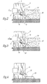
- FIG. 2 illustrates the normal functioning of the transport vehicle according to the invention.
- This drawing shows an edging 18, which extends alongside the path along which the vehicle travels.
- This edging which in particular could be a pavement or a platform, has in this case an sloping part 20, which forms the same angle ⁇ with the horizontal as the axis A' does.
- the roller 15, mounted on the pin 14, begins to rotate around its axis A'. Meanwhile, the arm 12 tends to pivot downwards, as indicated by arrow f 1 , being limited by the presence of the spring 16.
- the roller 15 therefore does not retract from the tyre, given that the lateral force to which it is subjected is relatively low. As a result, it continues to abut against the edging 18, in particular so that it ensures a guiding function for the vehicle.
- Figure 3 illustrates the behaviour of the transport vehicle, according to the invention, when it is subjected to a lateral movement, the component F of which is considerably higher than component f in figure 2.
- the roller 15 firstly abuts against the edging 18, as described above, so that the arm 12 also pivots in a downwards direction, as indicated by arrow f 2 .
- Figure 4 illustrates the functioning of the transport vehicle according to this invention, as it travels near an obstacle 22, which is for example a speed break device, or one known as a sleeping policeman, an abnormally prominent drain cover, or even a low kerb on a pavement when the vehicle crosses said pavement laterally.
- said obstacle 22 exerts an upwards force onto the roller 15, which tends to make the arm 12 pivot as indicated by arrow f 3 .
- FIGS 5 and 6 illustrate an alternative embodiment of the invention.
- the mechanical elements similar to those in figures 1 to 4 are marked with the same reference numbers, increased by 100.
- the transport vehicle according to this second embodiment differs from that in figures 1 to 4 in that the axle 108 does not have a point like that 10 shown in figures 1 to 4. At its free end, this axle 108 supports a cylinder body 110, secured by any appropriate means.
- This rod 112 supports a pin 114, with axis A', on which a roller 115 is mounted.
- the rod 112 and the roller 115 are therefore suitable to adopt two positions, that is to say firstly an opened out position illustrated in figure 5.
- the roller 115 then abuts against the edging 118, in the same way as has been described, in particular with reference to figure 2.
- This arrangement is more particularly suitable for a vehicle circulating in a dedicated lane, with the layout of the edging 118.
- the roller could be mounted on the axle, at the end of an arm, similar to that numbered 12, which is not however mounted so that it pivots on this axle.
- the arm and the axle are in this case made in one piece, being no longer connected to a pre-stressed spring.
- the rotation axis of the roller in relation to the pivoting arm or to the sliding rod, can be vertical.
- the roller is suitable to cooperate with an edging which also has a vertical side.
- the roller according to this invention can be adapted to the different axles of the vehicle.
- a steering axle it carries out a guiding function, whilst providing the driver with a sensory aid thanks to a kinaesthetic type information.
- the driver is able to directly perceive the vibration caused by the roller, or the stress return that it undergoes.
- roller according to this invention is used on a following axle, it is able to ensure a correction of the path in order to align the vehicle, but also to compensate for the vehicle's faults, such as skewed movement. Said roller also makes it possible to compensate for deviation due to external stresses, such as the lateral banking of the wheel or the presence of a side wind, as well as improving the gap between the vehicle and the platform, by bringing the vehicle to rest against the platform.
- the roller can be placed only on the right-hand side for a vehicle travelling on the right, but equally on the two sides, that is to say on the right and on the left. In the latter case, the roller can thus form a system for limiting the sway of the vehicle.
- the roller according to this invention can be included in the width without coming under any regulations, in the case of a non-guided system such as that described in figures 1 to 4, for example. However, in the case of a retractable system, such as that shown in figures 5 and 6, the roller is likely to exceed this overall width, so that it is then considered as a steering system.
- the roller according to this invention does not make the tyre work in the area in which it slides on the ground, but in the area of deviation of the tyre. This makes it possible to preserve the mechanical integrity of the tyre.
- this roller is positioned in such a way that it comes into contact with the edging before the tyre comes into contact with it, creating a path of approach with a low angle of incidence, in particular less than 2°.
Abstract
Description
- The present invention concerns a transport vehicle having wheels with tyres.
- The invention is aimed at all kinds of transport vehicles which cover a route which includes at least one station stop, during which people are likely to board the vehicle, or also to alight from it. It is aimed at such a vehicle, which may or may not be driven in a dedicated lane, in particular by the means of electric wires, of rails or even of optic means.
- This type of transport vehicle typically includes a chassis mounted on at least one axle, which supports wheels having rubber tyres. In these conditions, transport vehicles in the sense of the invention include in particular, but not exclusively, buses and also trolleybuses.
- This having being specified, the invention aims to improve such transport vehicles, in particular with regard to their steering, as well as the protection of the sides of their tyres.
- To this end, it has as its object a transport vehicle, notably a bus or a trolleybus, which includes a chassis, resting on at least one axle that is connected to wheels fitted with tyres, characterised in that the vehicle has at least one roller, mounted on a support that is secured in relation to said axle, this roller being fitted so that it rotates around an axis, so that it comes into contact with an edging that protrudes over the bearing surface of the vehicle.
- According to other characteristics of the invention:
- the roller is mounted on an arm which is suitable to pivot on the support around another axis;
- the other axis is parallel to the direction in which the transport vehicle is moving;
- provision is made for means of limiting the pivoting of the arm in relation to the support, particularly in a downwards direction;
- the means for limiting the pivoting are of an elastic nature, and notably include at least one spring;
- the roller is mounted on a rod suitable to slide in relation to the support;
- the support is a cylinder body, while the rod is a cylinder rod;
- the rotation axis of the roller extends in a plane perpendicular to the direction of the transport vehicle advancing;
- the rotation axis of the roller extends obliquely, specifically forming an angle of about 65° in relation to the horizontal;
- the rotation axis of the roller is vertical.
- The invention will be described below, with reference to the accompanying drawings, provided purely by way of non-limitative examples, in which:
- figure 1 is a back view, illustrating in particular an axle and a wheel on a tyre belonging to a transport vehicle according to the invention;
- figures 2 to 4 are back views similar to figure 1, illustrating three steps in the use of the transport vehicle illustrated in said figure 1; and
- figures 5 and 6 are back views, similar to figures 1 to 4, illustrating two steps in the use of a transport vehicle, according to an alternative embodiment of the invention.
- The transport vehicle according to this invention, illustrated partially in figures 1 to 4, is for example a bus that is guided on a dedicated lane, specifically by means that are not illustrated. However, as a non-limitative variant, it could also be a non-guided bus, or also a trolleybus.
- This vehicle includes, as is generally known, a body that is not illustrated, equipped with a platform that is also not illustrated, allowing users to access the vehicle. This body sits on wheels, only one of which, marked 2, is illustrated in figures 1 to 4. According to this invention, said
wheel 2 is equipped with a tyre, 4, while the bearing surface of the vehicle is marked S. - Furthermore, the vehicle is equipped with a
suspension 6, of a type that is generally known, allowing to vary the difference in height between the vehicle body and anaxle 8, on which thewheel 2 is mounted. At its side extremity, thisaxle 8 has apoint 10, which protrudes upwards obliquely, on which anarm 12 is articulated. The corresponding articulation axis, marked A, extends perpendicular to the diagram plane, so that it is parallel to the direction that the vehicle is travelling in. - At its tip opposite the
point 10, the articulatedarm 12 supports apin 14, with its main axis A', on which aclassic type roller 15 is mounted. This second axis A' is located in the plane of the diagram, so that it is perpendicular to the aforementioned advancing direction of the vehicle. Moreover, this axis A' forms an angle α with the horizontal, which is for instance around 65°. - Lastly, the invention includes a
prestressed spring 16, acting as a damping element, which is inserted between the walls opposite thepoint 10 and thearm 12. It will be observed that this spring is situated generally above the axis A, so that it limits the downwards movement of thearm 12, as will be seen in more detail below. - The working of the transport vehicle described above shall now be described below, with reference to figures 2 to 4.
- Figure 2 illustrates the normal functioning of the transport vehicle according to the invention. This drawing shows an edging 18, which extends alongside the path along which the vehicle travels. This edging, which in particular could be a pavement or a platform, has in this case an
sloping part 20, which forms the same angle α with the horizontal as the axis A' does. - We can presume that the transport vehicle has a component of lateral movement, marked f, which tends to push it back towards the edging 18. However, in this figure 2, it is presumed that the value of this component is within nominal ranges, i.e. the force f presents a relatively low value.
- In such conditions, the
roller 15, mounted on thepin 14, begins to rotate around its axis A'. Meanwhile, thearm 12 tends to pivot downwards, as indicated by arrow f 1, being limited by the presence of thespring 16. Theroller 15 therefore does not retract from the tyre, given that the lateral force to which it is subjected is relatively low. As a result, it continues to abut against the edging 18, in particular so that it ensures a guiding function for the vehicle. - Figure 3 illustrates the behaviour of the transport vehicle, according to the invention, when it is subjected to a lateral movement, the component F of which is considerably higher than component f in figure 2. In these conditions, the
roller 15 firstly abuts against the edging 18, as described above, so that thearm 12 also pivots in a downwards direction, as indicated by arrow f 2 . - However, contrary to what takes place in figure 2, the lateral force F is higher than the return force of the
spring 16, so that theroller 15 is entirely retracted into the tyre. This therefore allows theaxle 8 to be protected, as well as theroller 15 and thearm 12 which supports it. - Figure 4 illustrates the functioning of the transport vehicle according to this invention, as it travels near an
obstacle 22, which is for example a speed break device, or one known as a sleeping policeman, an abnormally prominent drain cover, or even a low kerb on a pavement when the vehicle crosses said pavement laterally. In such conditions, saidobstacle 22 exerts an upwards force onto theroller 15, which tends to make thearm 12 pivot as indicated by arrow f3. - Then, once the vehicle has passed over this obstacle, the
aforesaid arm 12 is pushed downwards again, by a return spring (not shown), so that it returns to its original position, illustrated in figure 1. This measure is advantageous as it allows the vehicle's road clearance to be maintained, whilst guaranteeing the mechanical integrity of thearm 12 and theroller 15. - Figures 5 and 6 illustrate an alternative embodiment of the invention. In these drawings, the mechanical elements similar to those in figures 1 to 4 are marked with the same reference numbers, increased by 100.
- The transport vehicle according to this second embodiment differs from that in figures 1 to 4 in that the
axle 108 does not have a point like that 10 shown in figures 1 to 4. At its free end, thisaxle 108 supports acylinder body 110, secured by any appropriate means. - It also includes a
cylinder rod 112, which is able to slide obliquely in relation to thebody 110. Thisrod 112 supports apin 114, with axis A', on which aroller 115 is mounted. - When functioning, the
rod 112 and theroller 115 are therefore suitable to adopt two positions, that is to say firstly an opened out position illustrated in figure 5. In such conditions, theroller 115 then abuts against the edging 118, in the same way as has been described, in particular with reference to figure 2. This arrangement is more particularly suitable for a vehicle circulating in a dedicated lane, with the layout of the edging 118. - On the other hand, when the transport vehicle is circulating in a general lane, the
rod 112 and theroller 115 are placed in their retracted position, illustrated in figure 6. To this regard, thisrod 112 is returned into thecylinder body 110, so that theroller 115 no longer protrudes laterally in relation to thetyre 104. This therefore allows the roller to be protected, as well as the cylinder rod, particularly from the significant mechanical stresses that they would be susceptible to. - The invention is not limited to the examples described and illustrated.
- Thus, it could be possible for the roller to be mounted on the axle, at the end of an arm, similar to that numbered 12, which is not however mounted so that it pivots on this axle. In other words, the arm and the axle are in this case made in one piece, being no longer connected to a pre-stressed spring.
- As an additional variation, which is also not illustrated, the rotation axis of the roller, in relation to the pivoting arm or to the sliding rod, can be vertical. In this case, the roller is suitable to cooperate with an edging which also has a vertical side.
- The roller according to this invention can be adapted to the different axles of the vehicle. Thus, in the case of a steering axle, it carries out a guiding function, whilst providing the driver with a sensory aid thanks to a kinaesthetic type information. Indeed, the driver is able to directly perceive the vibration caused by the roller, or the stress return that it undergoes.
- In the case in which the roller according to this invention is used on a following axle, it is able to ensure a correction of the path in order to align the vehicle, but also to compensate for the vehicle's faults, such as skewed movement. Said roller also makes it possible to compensate for deviation due to external stresses, such as the lateral banking of the wheel or the presence of a side wind, as well as improving the gap between the vehicle and the platform, by bringing the vehicle to rest against the platform.
- Furthermore, whatever type of axle it is mounted on, the roller can be placed only on the right-hand side for a vehicle travelling on the right, but equally on the two sides, that is to say on the right and on the left. In the latter case, the roller can thus form a system for limiting the sway of the vehicle.
- The roller according to this invention can be included in the width without coming under any regulations, in the case of a non-guided system such as that described in figures 1 to 4, for example. However, in the case of a retractable system, such as that shown in figures 5 and 6, the roller is likely to exceed this overall width, so that it is then considered as a steering system.
- It should be noted that, as an advantage, the roller according to this invention does not make the tyre work in the area in which it slides on the ground, but in the area of deviation of the tyre. This makes it possible to preserve the mechanical integrity of the tyre.
- Furthermore, this roller is positioned in such a way that it comes into contact with the edging before the tyre comes into contact with it, creating a path of approach with a low angle of incidence, in particular less than 2°.
Claims (10)
- Transport vehicle, in particular a bus or trolleybus, including a chassis, resting on at least one axle (8 ; 108) connected to wheels (2 ; 102) mounted on tyres (4 ; 104), characterised in that the vehicle includes at least one roller (15 ; 115), mounted on a support (10 ; 110) secured in relation to said axle (8 ; 108), said roller being mounted in a rotational manner around an axis (A'), being suitable to abut against an edging (18 ; 118) protruding in relation to a surface (S) on which the vehicle is travelling.
- Transport vehicle according to claim 1, characterised in that the roller (15) is mounted on an arm (12), which is suitable to pivot in relation to the support (10) around another axis (3).
- Transport vehicle according to claim 2, characterised in that the other axis (A) is parallel to the direction in which the transport vehicle is moving.
- Transport vehicle according to claim 2 or 3, characterised in that it includes means (16) for limiting the pivoting of the arm (12) in relation to the support (10), in particular in a downwards direction.
- Transport vehicle according to claim 4, characterised in that the means for limiting the pivoting are of an elastic nature, and in particular include at least one spring (16).
- Transport vehicle according to claim 1, characterised in that the roller (115) is mounted on a rod (112) suitable to slide in relation to the support (110).
- Transport vehicle according to claim 6, characterised in that the support is a cylinder body (110), whereas the rod is a cylinder rod (112).
- Transport vehicle according to any one of the previous claims, characterised in that the rotation axis (A') of the roller (15 ; 115) extends perpendicularly to the direction in which the transport vehicle is travelling.
- Transport vehicle according to claim 8, characterised in that the rotation axis (A') of the roller (15 ; 115) extends obliquely, in particular forming an angle (α) of around 65° in relation to the horizontal.
- Transport vehicle according to claim 8, characterised in that the rotation axis of the roller is vertical.
Applications Claiming Priority (1)
| Application Number | Priority Date | Filing Date | Title |
|---|---|---|---|
| FR0505823A FR2886909A1 (en) | 2005-06-08 | 2005-06-08 | TRANSPORT VEHICLE COMPRISING PNEUMATIC WHEELS |
Publications (2)
| Publication Number | Publication Date |
|---|---|
| EP1731401A1 true EP1731401A1 (en) | 2006-12-13 |
| EP1731401B1 EP1731401B1 (en) | 2008-11-12 |
Family
ID=35134539
Family Applications (1)
| Application Number | Title | Priority Date | Filing Date |
|---|---|---|---|
| EP06115123A Not-in-force EP1731401B1 (en) | 2005-06-08 | 2006-06-08 | Transport vehicle having wheels with tyres |
Country Status (5)
| Country | Link |
|---|---|
| EP (1) | EP1731401B1 (en) |
| AT (1) | ATE414001T1 (en) |
| DE (1) | DE602006003594D1 (en) |
| ES (1) | ES2317426T3 (en) |
| FR (1) | FR2886909A1 (en) |
Citations (2)
| Publication number | Priority date | Publication date | Assignee | Title |
|---|---|---|---|---|
| GB2154525A (en) * | 1984-02-18 | 1985-09-11 | Daimler Benz Ag | Transverse steering arrangement for track-guidable vehicles |
| EP0384105A1 (en) * | 1989-02-22 | 1990-08-29 | Man Technologie Aktiengesellschaft | Track guidance device for tyred vehicles |
-
2005
- 2005-06-08 FR FR0505823A patent/FR2886909A1/en not_active Withdrawn
-
2006
- 2006-06-08 EP EP06115123A patent/EP1731401B1/en not_active Not-in-force
- 2006-06-08 AT AT06115123T patent/ATE414001T1/en not_active IP Right Cessation
- 2006-06-08 DE DE602006003594T patent/DE602006003594D1/en active Active
- 2006-06-08 ES ES06115123T patent/ES2317426T3/en active Active
Patent Citations (2)
| Publication number | Priority date | Publication date | Assignee | Title |
|---|---|---|---|---|
| GB2154525A (en) * | 1984-02-18 | 1985-09-11 | Daimler Benz Ag | Transverse steering arrangement for track-guidable vehicles |
| EP0384105A1 (en) * | 1989-02-22 | 1990-08-29 | Man Technologie Aktiengesellschaft | Track guidance device for tyred vehicles |
Also Published As
| Publication number | Publication date |
|---|---|
| EP1731401B1 (en) | 2008-11-12 |
| ES2317426T3 (en) | 2009-04-16 |
| ATE414001T1 (en) | 2008-11-15 |
| FR2886909A1 (en) | 2006-12-15 |
| DE602006003594D1 (en) | 2008-12-24 |
Similar Documents
| Publication | Publication Date | Title |
|---|---|---|
| US8950800B1 (en) | Deployable lower leg stiffener for pedestrian protection | |
| CA2519048A1 (en) | Retractable step | |
| US20200001793A1 (en) | Front bumper slide-out step | |
| CN102264590A (en) | Low floor vehicle | |
| CN110177732B (en) | Rectifying structure for vehicle | |
| US8590909B2 (en) | Wheelie bar for leaf spring equipped cars | |
| EP1731401A1 (en) | Transport vehicle having wheels with tyres | |
| US20140261066A1 (en) | Retractable Rail Wheels for a Road/Rail Vehicle | |
| EP1859996B1 (en) | Transport vehicle equipped with access device for persons with reduced mobility | |
| EP1837444A1 (en) | Towed or on-board road and motorway signalling device | |
| US20020122694A1 (en) | Dump trailer for asphalt paving | |
| JP2011236586A (en) | Track snowplow | |
| KR101969234B1 (en) | Rear safety plate for cargo vehicles | |
| CN107813871B (en) | Automatic change vehicle rear wheel steering system | |
| US10252752B2 (en) | Splash-protection device for a wheel-mounted vehicle, and assembly having such device | |
| EP1787885B1 (en) | Transport vehicle having wheels with tyres | |
| AU2020343394A1 (en) | Protective device for rail vehicle | |
| KR101895007B1 (en) | safety loader | |
| KR200405957Y1 (en) | A central position system for large-sized vehicle | |
| US11242010B2 (en) | Pivoting step with roller | |
| AU2020202723B2 (en) | Pivoting step with roller | |
| AU626286B2 (en) | Track guidable omnibus | |
| CA2809950A1 (en) | Retractable rail wheels for a road/rail vehicle | |
| JP6435634B2 (en) | Automatic transfer system | |
| CN107042806A (en) | A kind of bumper suitable for highway driving |
Legal Events
| Date | Code | Title | Description |
|---|---|---|---|
| PUAI | Public reference made under article 153(3) epc to a published international application that has entered the european phase |
Free format text: ORIGINAL CODE: 0009012 |
|
| AK | Designated contracting states |
Kind code of ref document: A1 Designated state(s): AT BE BG CH CY CZ DE DK EE ES FI FR GB GR HU IE IS IT LI LT LU LV MC NL PL PT RO SE SI SK TR |
|
| AX | Request for extension of the european patent |
Extension state: AL BA HR MK YU |
|
| 17P | Request for examination filed |
Effective date: 20070611 |
|
| AKX | Designation fees paid |
Designated state(s): AT BE BG CH CY CZ DE DK EE ES FI FR GB GR HU IE IS IT LI LT LU LV MC NL PL PT RO SE SI SK TR |
|
| 17Q | First examination report despatched |
Effective date: 20070903 |
|
| GRAP | Despatch of communication of intention to grant a patent |
Free format text: ORIGINAL CODE: EPIDOSNIGR1 |
|
| GRAS | Grant fee paid |
Free format text: ORIGINAL CODE: EPIDOSNIGR3 |
|
| GRAA | (expected) grant |
Free format text: ORIGINAL CODE: 0009210 |
|
| AK | Designated contracting states |
Kind code of ref document: B1 Designated state(s): AT BE BG CH CY CZ DE DK EE ES FI FR GB GR HU IE IS IT LI LT LU LV MC NL PL PT RO SE SI SK TR |
|
| REG | Reference to a national code |
Ref country code: GB Ref legal event code: FG4D |
|
| REG | Reference to a national code |
Ref country code: CH Ref legal event code: EP |
|
| REG | Reference to a national code |
Ref country code: IE Ref legal event code: FG4D |
|
| REF | Corresponds to: |
Ref document number: 602006003594 Country of ref document: DE Date of ref document: 20081224 Kind code of ref document: P |
|
| REG | Reference to a national code |
Ref country code: SE Ref legal event code: TRGR |
|
| REG | Reference to a national code |
Ref country code: ES Ref legal event code: FG2A Ref document number: 2317426 Country of ref document: ES Kind code of ref document: T3 |
|
| LTIE | Lt: invalidation of european patent or patent extension |
Effective date: 20081112 |
|
| PG25 | Lapsed in a contracting state [announced via postgrant information from national office to epo] |
Ref country code: LT Free format text: LAPSE BECAUSE OF FAILURE TO SUBMIT A TRANSLATION OF THE DESCRIPTION OR TO PAY THE FEE WITHIN THE PRESCRIBED TIME-LIMIT Effective date: 20081112 Ref country code: AT Free format text: LAPSE BECAUSE OF FAILURE TO SUBMIT A TRANSLATION OF THE DESCRIPTION OR TO PAY THE FEE WITHIN THE PRESCRIBED TIME-LIMIT Effective date: 20081112 |
|
| PG25 | Lapsed in a contracting state [announced via postgrant information from national office to epo] |
Ref country code: LV Free format text: LAPSE BECAUSE OF FAILURE TO SUBMIT A TRANSLATION OF THE DESCRIPTION OR TO PAY THE FEE WITHIN THE PRESCRIBED TIME-LIMIT Effective date: 20081112 Ref country code: PL Free format text: LAPSE BECAUSE OF FAILURE TO SUBMIT A TRANSLATION OF THE DESCRIPTION OR TO PAY THE FEE WITHIN THE PRESCRIBED TIME-LIMIT Effective date: 20081112 Ref country code: SI Free format text: LAPSE BECAUSE OF FAILURE TO SUBMIT A TRANSLATION OF THE DESCRIPTION OR TO PAY THE FEE WITHIN THE PRESCRIBED TIME-LIMIT Effective date: 20081112 Ref country code: IS Free format text: LAPSE BECAUSE OF FAILURE TO SUBMIT A TRANSLATION OF THE DESCRIPTION OR TO PAY THE FEE WITHIN THE PRESCRIBED TIME-LIMIT Effective date: 20090312 Ref country code: FI Free format text: LAPSE BECAUSE OF FAILURE TO SUBMIT A TRANSLATION OF THE DESCRIPTION OR TO PAY THE FEE WITHIN THE PRESCRIBED TIME-LIMIT Effective date: 20081112 |
|
| PG25 | Lapsed in a contracting state [announced via postgrant information from national office to epo] |
Ref country code: BE Free format text: LAPSE BECAUSE OF FAILURE TO SUBMIT A TRANSLATION OF THE DESCRIPTION OR TO PAY THE FEE WITHIN THE PRESCRIBED TIME-LIMIT Effective date: 20081112 Ref country code: BG Free format text: LAPSE BECAUSE OF FAILURE TO SUBMIT A TRANSLATION OF THE DESCRIPTION OR TO PAY THE FEE WITHIN THE PRESCRIBED TIME-LIMIT Effective date: 20090212 Ref country code: EE Free format text: LAPSE BECAUSE OF FAILURE TO SUBMIT A TRANSLATION OF THE DESCRIPTION OR TO PAY THE FEE WITHIN THE PRESCRIBED TIME-LIMIT Effective date: 20081112 Ref country code: DK Free format text: LAPSE BECAUSE OF FAILURE TO SUBMIT A TRANSLATION OF THE DESCRIPTION OR TO PAY THE FEE WITHIN THE PRESCRIBED TIME-LIMIT Effective date: 20081112 Ref country code: RO Free format text: LAPSE BECAUSE OF FAILURE TO SUBMIT A TRANSLATION OF THE DESCRIPTION OR TO PAY THE FEE WITHIN THE PRESCRIBED TIME-LIMIT Effective date: 20081112 |
|
| PG25 | Lapsed in a contracting state [announced via postgrant information from national office to epo] |
Ref country code: CZ Free format text: LAPSE BECAUSE OF FAILURE TO SUBMIT A TRANSLATION OF THE DESCRIPTION OR TO PAY THE FEE WITHIN THE PRESCRIBED TIME-LIMIT Effective date: 20081112 Ref country code: PT Free format text: LAPSE BECAUSE OF FAILURE TO SUBMIT A TRANSLATION OF THE DESCRIPTION OR TO PAY THE FEE WITHIN THE PRESCRIBED TIME-LIMIT Effective date: 20090413 |
|
| PLBE | No opposition filed within time limit |
Free format text: ORIGINAL CODE: 0009261 |
|
| STAA | Information on the status of an ep patent application or granted ep patent |
Free format text: STATUS: NO OPPOSITION FILED WITHIN TIME LIMIT |
|
| PG25 | Lapsed in a contracting state [announced via postgrant information from national office to epo] |
Ref country code: SK Free format text: LAPSE BECAUSE OF FAILURE TO SUBMIT A TRANSLATION OF THE DESCRIPTION OR TO PAY THE FEE WITHIN THE PRESCRIBED TIME-LIMIT Effective date: 20081112 |
|
| 26N | No opposition filed |
Effective date: 20090813 |
|
| PG25 | Lapsed in a contracting state [announced via postgrant information from national office to epo] |
Ref country code: MC Free format text: LAPSE BECAUSE OF NON-PAYMENT OF DUE FEES Effective date: 20090630 |
|
| REG | Reference to a national code |
Ref country code: IE Ref legal event code: MM4A |
|
| PG25 | Lapsed in a contracting state [announced via postgrant information from national office to epo] |
Ref country code: IE Free format text: LAPSE BECAUSE OF NON-PAYMENT OF DUE FEES Effective date: 20090608 |
|
| PG25 | Lapsed in a contracting state [announced via postgrant information from national office to epo] |
Ref country code: GR Free format text: LAPSE BECAUSE OF FAILURE TO SUBMIT A TRANSLATION OF THE DESCRIPTION OR TO PAY THE FEE WITHIN THE PRESCRIBED TIME-LIMIT Effective date: 20090213 |
|
| REG | Reference to a national code |
Ref country code: CH Ref legal event code: PL |
|
| PG25 | Lapsed in a contracting state [announced via postgrant information from national office to epo] |
Ref country code: LI Free format text: LAPSE BECAUSE OF NON-PAYMENT OF DUE FEES Effective date: 20090630 Ref country code: CH Free format text: LAPSE BECAUSE OF NON-PAYMENT OF DUE FEES Effective date: 20090630 Ref country code: IT Free format text: LAPSE BECAUSE OF NON-PAYMENT OF DUE FEES Effective date: 20100608 |
|
| PG25 | Lapsed in a contracting state [announced via postgrant information from national office to epo] |
Ref country code: LU Free format text: LAPSE BECAUSE OF NON-PAYMENT OF DUE FEES Effective date: 20090608 Ref country code: CH Free format text: LAPSE BECAUSE OF NON-PAYMENT OF DUE FEES Effective date: 20100630 Ref country code: LI Free format text: LAPSE BECAUSE OF NON-PAYMENT OF DUE FEES Effective date: 20100630 |
|
| PG25 | Lapsed in a contracting state [announced via postgrant information from national office to epo] |
Ref country code: HU Free format text: LAPSE BECAUSE OF FAILURE TO SUBMIT A TRANSLATION OF THE DESCRIPTION OR TO PAY THE FEE WITHIN THE PRESCRIBED TIME-LIMIT Effective date: 20090513 |
|
| PGRI | Patent reinstated in contracting state [announced from national office to epo] |
Ref country code: IT Effective date: 20110616 |
|
| PG25 | Lapsed in a contracting state [announced via postgrant information from national office to epo] |
Ref country code: TR Free format text: LAPSE BECAUSE OF FAILURE TO SUBMIT A TRANSLATION OF THE DESCRIPTION OR TO PAY THE FEE WITHIN THE PRESCRIBED TIME-LIMIT Effective date: 20081112 |
|
| PG25 | Lapsed in a contracting state [announced via postgrant information from national office to epo] |
Ref country code: CY Free format text: LAPSE BECAUSE OF FAILURE TO SUBMIT A TRANSLATION OF THE DESCRIPTION OR TO PAY THE FEE WITHIN THE PRESCRIBED TIME-LIMIT Effective date: 20081112 |
|
| PGFP | Annual fee paid to national office [announced via postgrant information from national office to epo] |
Ref country code: GB Payment date: 20140508 Year of fee payment: 9 |
|
| PGFP | Annual fee paid to national office [announced via postgrant information from national office to epo] |
Ref country code: DE Payment date: 20140508 Year of fee payment: 9 Ref country code: FR Payment date: 20140509 Year of fee payment: 9 Ref country code: IT Payment date: 20140618 Year of fee payment: 9 Ref country code: ES Payment date: 20140509 Year of fee payment: 9 Ref country code: SE Payment date: 20140507 Year of fee payment: 9 |
|
| PGFP | Annual fee paid to national office [announced via postgrant information from national office to epo] |
Ref country code: NL Payment date: 20140507 Year of fee payment: 9 |
|
| REG | Reference to a national code |
Ref country code: DE Ref legal event code: R119 Ref document number: 602006003594 Country of ref document: DE |
|
| PG25 | Lapsed in a contracting state [announced via postgrant information from national office to epo] |
Ref country code: IT Free format text: LAPSE BECAUSE OF NON-PAYMENT OF DUE FEES Effective date: 20150608 |
|
| REG | Reference to a national code |
Ref country code: SE Ref legal event code: EUG |
|
| GBPC | Gb: european patent ceased through non-payment of renewal fee |
Effective date: 20150608 |
|
| PG25 | Lapsed in a contracting state [announced via postgrant information from national office to epo] |
Ref country code: SE Free format text: LAPSE BECAUSE OF NON-PAYMENT OF DUE FEES Effective date: 20150609 |
|
| REG | Reference to a national code |
Ref country code: NL Ref legal event code: MM Effective date: 20150701 |
|
| REG | Reference to a national code |
Ref country code: FR Ref legal event code: ST Effective date: 20160229 |
|
| PG25 | Lapsed in a contracting state [announced via postgrant information from national office to epo] |
Ref country code: GB Free format text: LAPSE BECAUSE OF NON-PAYMENT OF DUE FEES Effective date: 20150608 Ref country code: NL Free format text: LAPSE BECAUSE OF NON-PAYMENT OF DUE FEES Effective date: 20150701 Ref country code: DE Free format text: LAPSE BECAUSE OF NON-PAYMENT OF DUE FEES Effective date: 20160101 |
|
| PG25 | Lapsed in a contracting state [announced via postgrant information from national office to epo] |
Ref country code: FR Free format text: LAPSE BECAUSE OF NON-PAYMENT OF DUE FEES Effective date: 20150630 |
|
| REG | Reference to a national code |
Ref country code: ES Ref legal event code: FD2A Effective date: 20160728 |
|
| PG25 | Lapsed in a contracting state [announced via postgrant information from national office to epo] |
Ref country code: ES Free format text: LAPSE BECAUSE OF NON-PAYMENT OF DUE FEES Effective date: 20150609 |