EP0383687B1 - Système de tubes radiants pour fours de chauffage - Google Patents
Système de tubes radiants pour fours de chauffage Download PDFInfo
- Publication number
- EP0383687B1 EP0383687B1 EP90400409A EP90400409A EP0383687B1 EP 0383687 B1 EP0383687 B1 EP 0383687B1 EP 90400409 A EP90400409 A EP 90400409A EP 90400409 A EP90400409 A EP 90400409A EP 0383687 B1 EP0383687 B1 EP 0383687B1
- Authority
- EP
- European Patent Office
- Prior art keywords
- bend
- tubes
- cold
- tube
- burner
- Prior art date
- Legal status (The legal status is an assumption and is not a legal conclusion. Google has not performed a legal analysis and makes no representation as to the accuracy of the status listed.)
- Expired - Lifetime
Links
- 238000010438 heat treatment Methods 0.000 title claims abstract description 19
- 239000002184 metal Substances 0.000 claims abstract description 8
- 239000000567 combustion gas Substances 0.000 claims abstract description 7
- 238000012546 transfer Methods 0.000 claims abstract description 6
- 238000009826 distribution Methods 0.000 claims description 8
- 235000000396 iron Nutrition 0.000 claims 2
- 230000000063 preceeding effect Effects 0.000 claims 2
- 238000003466 welding Methods 0.000 description 4
- 238000013461 design Methods 0.000 description 2
- 238000000034 method Methods 0.000 description 2
- 230000005855 radiation Effects 0.000 description 2
- 238000010792 warming Methods 0.000 description 2
- 238000013459 approach Methods 0.000 description 1
- 238000005266 casting Methods 0.000 description 1
- 238000007796 conventional method Methods 0.000 description 1
- 230000000694 effects Effects 0.000 description 1
- 238000009434 installation Methods 0.000 description 1
- 238000013507 mapping Methods 0.000 description 1
- 239000000463 material Substances 0.000 description 1
- 238000005457 optimization Methods 0.000 description 1
- 238000011084 recovery Methods 0.000 description 1
Images

Classifications
-
- F—MECHANICAL ENGINEERING; LIGHTING; HEATING; WEAPONS; BLASTING
- F23—COMBUSTION APPARATUS; COMBUSTION PROCESSES
- F23C—METHODS OR APPARATUS FOR COMBUSTION USING FLUID FUEL OR SOLID FUEL SUSPENDED IN A CARRIER GAS OR AIR
- F23C3/00—Combustion apparatus characterised by the shape of the combustion chamber
- F23C3/002—Combustion apparatus characterised by the shape of the combustion chamber the chamber having an elongated tubular form, e.g. for a radiant tube
-
- F—MECHANICAL ENGINEERING; LIGHTING; HEATING; WEAPONS; BLASTING
- F27—FURNACES; KILNS; OVENS; RETORTS
- F27B—FURNACES, KILNS, OVENS, OR RETORTS IN GENERAL; OPEN SINTERING OR LIKE APPARATUS
- F27B9/00—Furnaces through which the charge is moved mechanically, e.g. of tunnel type; Similar furnaces in which the charge moves by gravity
- F27B9/06—Furnaces through which the charge is moved mechanically, e.g. of tunnel type; Similar furnaces in which the charge moves by gravity heated without contact between combustion gases and charge; electrically heated
- F27B9/068—Furnaces through which the charge is moved mechanically, e.g. of tunnel type; Similar furnaces in which the charge moves by gravity heated without contact between combustion gases and charge; electrically heated heated by radiant tubes, the tube being heated by a hot medium, e.g. hot gases
-
- F—MECHANICAL ENGINEERING; LIGHTING; HEATING; WEAPONS; BLASTING
- F28—HEAT EXCHANGE IN GENERAL
- F28F—DETAILS OF HEAT-EXCHANGE AND HEAT-TRANSFER APPARATUS, OF GENERAL APPLICATION
- F28F9/00—Casings; Header boxes; Auxiliary supports for elements; Auxiliary members within casings
- F28F9/007—Auxiliary supports for elements
- F28F9/013—Auxiliary supports for elements for tubes or tube-assemblies
Definitions
- the present invention relates to improvements made to the systems of radiant tubes used in particular in the furnaces for heating strips of metal products during parade.
- radiant tubes generally having a W configuration, also called a double pin, are generally used, these tubes ensuring the thermal transfer between the combustion gases emitted by a burner and the product to be heated, in particular a metal strip. continuously moving. The heat transfer takes place by radiation between the radiant tube system and the product to be heated and by convection / radiation inside the radiant tubes.
- the combustion gases at the outlet of the radiant tube system have a temperature of around 1000 ° C while the temperature of the radiant tubes is on average 950 ° C with a local maximum of the order of 1050 ° C.
- the present licensee has carried out an in-depth study of deformations by thermal expansion as well as the stress network associated with these expansions, these constraints. appearing during heating of the radiant tubes and during operation in stabilized mode or not.
- the aim of this study was to find the means making it possible to optimize the distribution of the stresses by taking into account the creep resistance of the materials which constitute the system of radiant tubes, this creep resistance varying strongly as a function of the temperature.
- the present invention therefore relates to a system of radiant tubes which has been improved by taking account of the results of said study.
- the simple support which supports the cold elbow is produced in the form of a console on which the cold elbow rests, before heating up the radiant tube, the cold elbow lifting up to leave this support as soon as heating.
- the cold elbow and the hot elbow are connected by means of brackets respectively from the foundry with its respective elbow, these brackets being connected together using a key or the like.
- the means ensuring the connection on the burner side between the intermediate elbow and the lower tube is produced using a leg from the foundry with this intermediate elbow on which is welded a stirrup-shaped part which can come '' press on the lower tube, an intermediate clearance being provided between the stirrup and the lower tube, the distribution of the stresses of the radiant tube being a function of the value of this intermediate clearance, and the resumption of the force generated by the intermediate elbow being provided by the lower tube in the part where it is the coldest.
- the heating furnace is used for the heat treatment of strips, in particular of metal strips 12, 12 ′ moving continuously in the furnace (process on parade).
- the heating is carried out using radiant tubes whose system has been designated as a whole by the reference 10, this system having as known a configuration in W or double pin.
- a burner 14 is provided outside the enclosure of the furnace and the combustion gases emitted by this burner pass through the system of radiant tubes 10 before escaping to the atmosphere.
- the radiant tubes therefore provide heat transfer between the combustion gases emitted by the burner 14 and the product 12, 12 ′ to be heated.
- the burner 14 is positioned on the lower branch of the system of radiant tubes, that is to say at the end of the lower tube 16 which constitutes the hot tube.
- the elbow 18 which extends the hot tube 16 constitutes the hot elbow of the system 10.
- the elbow 20 will be designated hereinafter intermediate elbow and the upper elbow 22 will be designated by cold elbow, this elbow opening onto the upper tube 24 which constitutes the tube cold radiant tube system 10.
- the cold elbow is provided with a support device the function of which boils down to a simple press.
- this simple support is produced in the form of a console 28 on which a support plate 26 can come to rest, made integral by any appropriate means with the cold elbow 22.
- the elbow associated with the support is the cold elbow 22 in which the most significant stresses are acceptable.
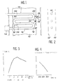
- FIG. 3 the variation in the temperature of the tube system 10 is shown as a function of its length, and the position of the respective elbows 18, 20, 22 is plotted on the abscissa.
- FIG. 4 the variation in the admissible creep stress as a function of the temperature of the tube system 10. This curve shows although the allowable stresses in the cold elbow region are much higher than those acceptable in the hot elbow. Such an arrangement is essential for the optimization of the constraint network.
- connection system between the hot elbow 18 and the cold elbow 22, this connection system being essentially characterized by the fact that it does not comprise any intermediate part (link).
- the elbow 18 is provided with a square 32 coming directly from the foundry with this hot elbow 18 and likewise the cold elbow 22 is provided with a similar square 30 also come directly from foundry with this cold elbow 22.
- the brackets 30 and 32 are obtained directly during the casting of the elbows of which they are respectively part. In no case should these brackets be added by welding to the elbows since such welds generate stress concentrations and risks of microcracking at locations where the stresses are maximum during operation.
- brackets 30 and 32 are connected by means of a connecting piece which can be produced in the form of a key such as 34, the design being such that the games allow relative movements of the hot 18 and cold 22 elbows when warming up, during operation of the oven in stabilized mode and during transients (power variation of the system of radiant tubes 10).
- the improved radiant tube system according to the present invention also comprises a connection between the intermediate elbow 20 and the hot lower tube 16, burner side 14.
- a connection between the intermediate elbow 20 and the hot lower tube 16, burner side 14. Such a system visible in FIG. 1 and shown in more detail in FIGS. 7 and 8 is essential for optimizing the distribution of system constraints 10.
- this connection system comprises a piece 36 in the shape of a tab, coming directly from the foundry with the intermediate bend 20 (any welding between the bend 20 and a connection piece such as 36 being prohibited for reasons indicated above with respect to the brackets 30 and 32) and a piece 38 in the shape of a stirrup which can be mounted on the lug 36 by welding since this lug does not support any constraint.
- connection by welding between the tab 36 and the part 38 in the shape of a stirrup is carried out after checking the intermediate clearance "j" between the stirrup 38 and the hot lower tube 16.
- the subsequent distribution of the components of the system of radiant tubes 10 depends on the value of this infill. In fact, when the oven is warming up, the intermediate bend 20 approaches the lower tube 16 up to the intermediate clearance "j" produced when cold and its movement is thus limited. This situation corresponds to a mapping of the distribution of the particular constraints for each infill set.
- connection of the lower 16 and upper 24 tubes with the sheet metal of the furnace can be carried out by any suitable means and in particular by any conventional technique. It will however be noted that the use of expansion bellows on one of the branches of the system of radiant tubes 10, as is provided in certain conventional embodiments, brings here more drawbacks than advantages and under these conditions the invention plans to carry out the connection between the lower and upper tubes and the sheet metal of the furnace without using expansion bellows.
Landscapes
- Engineering & Computer Science (AREA)
- Mechanical Engineering (AREA)
- General Engineering & Computer Science (AREA)
- Chemical & Material Sciences (AREA)
- Combustion & Propulsion (AREA)
- Physics & Mathematics (AREA)
- Thermal Sciences (AREA)
- Combustion Of Fluid Fuel (AREA)
- Resistance Heating (AREA)
- Heat Treatment Of Articles (AREA)
- Gas Burners (AREA)
- Pipe Accessories (AREA)
- Electric Stoves And Ranges (AREA)
- Engine Equipment That Uses Special Cycles (AREA)
- Bending Of Plates, Rods, And Pipes (AREA)
- Baking, Grill, Roasting (AREA)
- Drying Of Solid Materials (AREA)
- Yarns And Mechanical Finishing Of Yarns Or Ropes (AREA)
- Production Of Liquid Hydrocarbon Mixture For Refining Petroleum (AREA)
- Muffle Furnaces And Rotary Kilns (AREA)
Applications Claiming Priority (2)
| Application Number | Priority Date | Filing Date | Title |
|---|---|---|---|
| FR8902117 | 1989-02-17 | ||
| FR8902117A FR2643447B1 (fr) | 1989-02-17 | 1989-02-17 | Systeme de tubes radiants pour fours de chauffage |
Publications (2)
| Publication Number | Publication Date |
|---|---|
| EP0383687A1 EP0383687A1 (fr) | 1990-08-22 |
| EP0383687B1 true EP0383687B1 (fr) | 1994-06-08 |
Family
ID=9378900
Family Applications (1)
| Application Number | Title | Priority Date | Filing Date |
|---|---|---|---|
| EP90400409A Expired - Lifetime EP0383687B1 (fr) | 1989-02-17 | 1990-02-14 | Système de tubes radiants pour fours de chauffage |
Country Status (10)
| Country | Link |
|---|---|
| US (1) | US5042452A (el) |
| EP (1) | EP0383687B1 (el) |
| JP (1) | JPH0674881B2 (el) |
| AT (1) | ATE107015T1 (el) |
| DE (2) | DE383687T1 (el) |
| ES (1) | ES2017061T3 (el) |
| FR (1) | FR2643447B1 (el) |
| GR (1) | GR900300158T1 (el) |
| NO (1) | NO177105C (el) |
| RU (1) | RU1773299C (el) |
Families Citing this family (12)
| Publication number | Priority date | Publication date | Assignee | Title |
|---|---|---|---|---|
| FR2685437B1 (fr) * | 1991-12-23 | 1994-01-28 | Stein Industrie | Dispositif d'appui sur une charpente fixe d'une masse reliee en porte-a-faux a un element mobile. |
| US5370530A (en) * | 1993-03-24 | 1994-12-06 | Italimpianti Of America, Inc. | Rolls for high temperature roller hearth furnaces |
| US5362230A (en) * | 1993-03-24 | 1994-11-08 | Italimpianti Of America, Inc. | Rolls for high temperature roller hearth furnaces |
| JP3855369B2 (ja) * | 1997-05-26 | 2006-12-06 | Jfeスチール株式会社 | ラジアントチューブの支持装置 |
| US7487745B2 (en) * | 2005-04-28 | 2009-02-10 | Mark Rettig | Boiler tube position retainer assembly |
| US7559294B2 (en) * | 2007-04-26 | 2009-07-14 | Babcock & Wilcox Power Generation Group Inc. | End support configuration for steam tubes of a superheater or reheater |
| DE202008009065U1 (de) * | 2008-07-04 | 2008-10-09 | WS Wärmeprozesstechnik GmbH | Strahlungsheizanordnung mit Verzugkompensation |
| AT508264B1 (de) * | 2009-10-13 | 2010-12-15 | Ebner Ind Ofenbau | Vorrichtung zur wärmebehandlung von blechbändern |
| AT508368B1 (de) | 2009-10-13 | 2011-01-15 | Ebner Ind Ofenbau | Vorrichtung zur wärmebehandlung von blechbändern |
| JP6028595B2 (ja) * | 2013-01-29 | 2016-11-16 | 新日鐵住金株式会社 | ラジアントチューブを用いた加熱炉 |
| ES2807833T3 (es) * | 2016-09-07 | 2021-02-24 | Doosan Lentjes Gmbh | Aparato de lecho fluidizado circulante |
| CN110748885A (zh) * | 2019-11-18 | 2020-02-04 | 江苏优泽科技有限公司 | 一种辐射管 |
Family Cites Families (13)
| Publication number | Priority date | Publication date | Assignee | Title |
|---|---|---|---|---|
| US2204144A (en) * | 1935-10-31 | 1940-06-11 | Babcock & Wilcox Co | Fluid heat exchange apparatus |
| GB487764A (en) * | 1937-03-01 | 1938-06-24 | Surface Combustion Corp | Improvements in heat radiating combustion flues for furnaces |
| US2652037A (en) * | 1947-09-03 | 1953-09-15 | Du Pont | Heat exchange apparatus |
| US2695220A (en) * | 1950-09-27 | 1954-11-23 | Socony Vacuum Oil Co Inc | Kiln |
| US3055349A (en) * | 1959-05-11 | 1962-09-25 | Babcock & Wilcox Co | Tubular fluid heater and support therefor |
| CH420230A (de) * | 1964-09-03 | 1966-09-15 | Sulzer Ag | Wärmeübertrager |
| US3385271A (en) * | 1967-01-31 | 1968-05-28 | Selas Corp Of America | Tube heater |
| GB1396796A (en) * | 1972-07-21 | 1975-06-04 | Skoda Np | Heat radiating tube support |
| CH577117A5 (el) * | 1974-04-29 | 1976-06-30 | Sulzer Ag | |
| LU84040A1 (fr) * | 1982-03-26 | 1983-11-17 | Cockerill Sambre Sa | Supports ameliores de corps de chauffe de fours de recuit |
| JPH0226924Y2 (el) * | 1985-05-28 | 1990-07-20 | ||
| US4796690A (en) * | 1985-11-18 | 1989-01-10 | Foster Wheeler Energy Corporation | Support system for heat exchange tube |
| US4878480A (en) * | 1988-07-26 | 1989-11-07 | Gas Research Institute | Radiant tube fired with two bidirectional burners |
-
1989
- 1989-02-17 FR FR8902117A patent/FR2643447B1/fr not_active Expired - Lifetime
-
1990
- 1990-02-14 ES ES90400409T patent/ES2017061T3/es not_active Expired - Lifetime
- 1990-02-14 AT AT90400409T patent/ATE107015T1/de not_active IP Right Cessation
- 1990-02-14 EP EP90400409A patent/EP0383687B1/fr not_active Expired - Lifetime
- 1990-02-14 DE DE199090400409T patent/DE383687T1/de active Pending
- 1990-02-14 DE DE69009519T patent/DE69009519T2/de not_active Expired - Fee Related
- 1990-02-16 RU SU904743223A patent/RU1773299C/ru active
- 1990-02-16 US US07/481,059 patent/US5042452A/en not_active Expired - Lifetime
- 1990-02-16 NO NO900763A patent/NO177105C/no unknown
- 1990-02-16 JP JP2036018A patent/JPH0674881B2/ja not_active Expired - Fee Related
-
1991
- 1991-09-27 GR GR90300158T patent/GR900300158T1/el unknown
Also Published As
| Publication number | Publication date |
|---|---|
| EP0383687A1 (fr) | 1990-08-22 |
| NO177105B (no) | 1995-04-10 |
| NO900763L (no) | 1990-08-20 |
| ES2017061A4 (es) | 1991-01-01 |
| JPH0674881B2 (ja) | 1994-09-21 |
| JPH02254208A (ja) | 1990-10-15 |
| GR900300158T1 (en) | 1991-09-27 |
| US5042452A (en) | 1991-08-27 |
| NO900763D0 (no) | 1990-02-16 |
| NO177105C (no) | 1995-07-19 |
| DE383687T1 (de) | 1991-01-17 |
| ATE107015T1 (de) | 1994-06-15 |
| FR2643447B1 (fr) | 1991-10-04 |
| DE69009519D1 (de) | 1994-07-14 |
| DE69009519T2 (de) | 1994-09-29 |
| RU1773299C (ru) | 1992-10-30 |
| FR2643447A1 (fr) | 1990-08-24 |
| ES2017061T3 (es) | 1994-08-16 |
Similar Documents
| Publication | Publication Date | Title |
|---|---|---|
| EP0383687B1 (fr) | Système de tubes radiants pour fours de chauffage | |
| FR2579268A1 (fr) | Bruleur pour moteur stirling | |
| EP2530380B1 (fr) | Installation de chauffage comprenant un appareil de chauffage à bois, une sortie de bâtiment et un conduit de liaison | |
| EP1217302B1 (fr) | Dispositif chauffant radiant comportant une tête chauffante orientable | |
| FR3029272A1 (fr) | Appareil de cuisson a gaz, notamment un four a gaz | |
| FR2488277A1 (fr) | Four pour le chauffage de metal et en particulier de profiles intermediaires avant leur laminage | |
| FR2478266A1 (fr) | Bruleur a gaz a rayonnement infrarouge retourne vers la base | |
| CH665013A5 (fr) | Fourneau. | |
| FR2831658A1 (fr) | Four a sole annulaire | |
| BE1027839B1 (fr) | Élément de chauffage radiant à extrémité libre | |
| FR2468839A1 (fr) | Ensemble combine de cuisson d'aliments et chauffage de locaux | |
| EP1147340A1 (fr) | Bruleur a gazeification | |
| CA2288079A1 (fr) | Appareil de chauffage | |
| FR2678356A1 (fr) | Bruleur catalytique a air induit. | |
| EP4162848A1 (fr) | Allume-feu électrique | |
| FR2831657A1 (fr) | Four a sole annulaire a tube foyer polygonal | |
| BE397719A (el) | ||
| FR2465955A1 (fr) | Chaudiere de chauffage central et installation de chauffage central comportant une telle chaudiere | |
| FR3037637A1 (fr) | Dispositif de chauffage d'air d'inflammation de gaz de combustion pour installation de chauffage par combustion d'un combustible ligneux | |
| BE460058A (el) | ||
| IES960711A2 (en) | Method of converting a cooker or stove from solid fuel to oil or gas | |
| CH184576A (fr) | Chaudière en fonte à combustible solide avec installation pour la transformer en une chaudière à combustible liquide ou gazeux. | |
| EP0298790A1 (fr) | Installation de chauffage par rayonnement thermique | |
| BE363962A (el) | ||
| BE506938A (el) |
Legal Events
| Date | Code | Title | Description |
|---|---|---|---|
| PUAI | Public reference made under article 153(3) epc to a published international application that has entered the european phase |
Free format text: ORIGINAL CODE: 0009012 |
|
| AK | Designated contracting states |
Kind code of ref document: A1 Designated state(s): AT BE CH DE DK ES GB GR IT LI LU NL SE |
|
| ITCL | It: translation for ep claims filed |
Representative=s name: BARZANO' E ZANARDO MILANO S.P.A. |
|
| GBC | Gb: translation of claims filed (gb section 78(7)/1977) | ||
| TCNL | Nl: translation of patent claims filed | ||
| TCAT | At: translation of patent claims filed | ||
| DET | De: translation of patent claims | ||
| 17P | Request for examination filed |
Effective date: 19901229 |
|
| 17Q | First examination report despatched |
Effective date: 19930318 |
|
| GRAA | (expected) grant |
Free format text: ORIGINAL CODE: 0009210 |
|
| ITF | It: translation for a ep patent filed | ||
| AK | Designated contracting states |
Kind code of ref document: B1 Designated state(s): AT BE CH DE DK ES GB GR IT LI LU NL SE |
|
| PG25 | Lapsed in a contracting state [announced via postgrant information from national office to epo] |
Ref country code: DK Effective date: 19940608 Ref country code: GR Free format text: LAPSE BECAUSE OF FAILURE TO SUBMIT A TRANSLATION OF THE DESCRIPTION OR TO PAY THE FEE WITHIN THE PRESCRIBED TIME-LIMIT Effective date: 19940608 |
|
| REF | Corresponds to: |
Ref document number: 107015 Country of ref document: AT Date of ref document: 19940615 Kind code of ref document: T |
|
| GBT | Gb: translation of ep patent filed (gb section 77(6)(a)/1977) |
Effective date: 19940610 |
|
| REF | Corresponds to: |
Ref document number: 69009519 Country of ref document: DE Date of ref document: 19940714 |
|
| REG | Reference to a national code |
Ref country code: ES Ref legal event code: FG2A Ref document number: 2017061 Country of ref document: ES Kind code of ref document: T3 |
|
| EAL | Se: european patent in force in sweden |
Ref document number: 90400409.0 |
|
| PLBE | No opposition filed within time limit |
Free format text: ORIGINAL CODE: 0009261 |
|
| STAA | Information on the status of an ep patent application or granted ep patent |
Free format text: STATUS: NO OPPOSITION FILED WITHIN TIME LIMIT |
|
| 26N | No opposition filed | ||
| REG | Reference to a national code |
Ref country code: GB Ref legal event code: IF02 |
|
| PGFP | Annual fee paid to national office [announced via postgrant information from national office to epo] |
Ref country code: CH Payment date: 20020128 Year of fee payment: 13 |
|
| PG25 | Lapsed in a contracting state [announced via postgrant information from national office to epo] |
Ref country code: CH Free format text: LAPSE BECAUSE OF NON-PAYMENT OF DUE FEES Effective date: 20030228 Ref country code: LI Free format text: LAPSE BECAUSE OF NON-PAYMENT OF DUE FEES Effective date: 20030228 |
|
| REG | Reference to a national code |
Ref country code: CH Ref legal event code: PL |
|
| PGFP | Annual fee paid to national office [announced via postgrant information from national office to epo] |
Ref country code: GB Payment date: 20050202 Year of fee payment: 16 |
|
| PGFP | Annual fee paid to national office [announced via postgrant information from national office to epo] |
Ref country code: SE Payment date: 20050210 Year of fee payment: 16 |
|
| PGFP | Annual fee paid to national office [announced via postgrant information from national office to epo] |
Ref country code: NL Payment date: 20050214 Year of fee payment: 16 |
|
| PGFP | Annual fee paid to national office [announced via postgrant information from national office to epo] |
Ref country code: LU Payment date: 20050215 Year of fee payment: 16 |
|
| PG25 | Lapsed in a contracting state [announced via postgrant information from national office to epo] |
Ref country code: GB Free format text: LAPSE BECAUSE OF NON-PAYMENT OF DUE FEES Effective date: 20060214 |
|
| PG25 | Lapsed in a contracting state [announced via postgrant information from national office to epo] |
Ref country code: SE Free format text: LAPSE BECAUSE OF NON-PAYMENT OF DUE FEES Effective date: 20060215 |
|
| PG25 | Lapsed in a contracting state [announced via postgrant information from national office to epo] |
Ref country code: LU Free format text: LAPSE BECAUSE OF NON-PAYMENT OF DUE FEES Effective date: 20060228 |
|
| PG25 | Lapsed in a contracting state [announced via postgrant information from national office to epo] |
Ref country code: NL Free format text: LAPSE BECAUSE OF NON-PAYMENT OF DUE FEES Effective date: 20060901 |
|
| EUG | Se: european patent has lapsed | ||
| GBPC | Gb: european patent ceased through non-payment of renewal fee |
Effective date: 20060214 |
|
| NLV4 | Nl: lapsed or anulled due to non-payment of the annual fee |
Effective date: 20060901 |
|
| PGFP | Annual fee paid to national office [announced via postgrant information from national office to epo] |
Ref country code: ES Payment date: 20080206 Year of fee payment: 19 |
|
| PGFP | Annual fee paid to national office [announced via postgrant information from national office to epo] |
Ref country code: DE Payment date: 20080208 Year of fee payment: 19 Ref country code: IT Payment date: 20080213 Year of fee payment: 19 |
|
| PGFP | Annual fee paid to national office [announced via postgrant information from national office to epo] |
Ref country code: AT Payment date: 20080124 Year of fee payment: 19 |
|
| PGFP | Annual fee paid to national office [announced via postgrant information from national office to epo] |
Ref country code: BE Payment date: 20090127 Year of fee payment: 20 |
|
| PG25 | Lapsed in a contracting state [announced via postgrant information from national office to epo] |
Ref country code: AT Free format text: LAPSE BECAUSE OF NON-PAYMENT OF DUE FEES Effective date: 20090214 |
|
| PG25 | Lapsed in a contracting state [announced via postgrant information from national office to epo] |
Ref country code: DE Free format text: LAPSE BECAUSE OF NON-PAYMENT OF DUE FEES Effective date: 20090901 |
|
| BE20 | Be: patent expired |
Owner name: *STEIN HEURTEY Effective date: 20100214 |
|
| REG | Reference to a national code |
Ref country code: ES Ref legal event code: FD2A Effective date: 20090216 |
|
| PG25 | Lapsed in a contracting state [announced via postgrant information from national office to epo] |
Ref country code: ES Free format text: LAPSE BECAUSE OF NON-PAYMENT OF DUE FEES Effective date: 20090216 |
|
| PG25 | Lapsed in a contracting state [announced via postgrant information from national office to epo] |
Ref country code: IT Free format text: LAPSE BECAUSE OF NON-PAYMENT OF DUE FEES Effective date: 20090214 |