EP0380907B2 - Druckgasschalter für Hoch- und Mittelspannung - Google Patents
Druckgasschalter für Hoch- und Mittelspannung Download PDFInfo
- Publication number
- EP0380907B2 EP0380907B2 EP90100019A EP90100019A EP0380907B2 EP 0380907 B2 EP0380907 B2 EP 0380907B2 EP 90100019 A EP90100019 A EP 90100019A EP 90100019 A EP90100019 A EP 90100019A EP 0380907 B2 EP0380907 B2 EP 0380907B2
- Authority
- EP
- European Patent Office
- Prior art keywords
- piston
- circuit breaker
- tube
- arc
- cylinder
- Prior art date
- Legal status (The legal status is an assumption and is not a legal conclusion. Google has not performed a legal analysis and makes no representation as to the accuracy of the status listed.)
- Expired - Lifetime
Links
- 229910052751 metal Inorganic materials 0.000 claims description 3
- 239000002184 metal Substances 0.000 claims description 3
- 238000007599 discharging Methods 0.000 claims 1
- 239000007789 gas Substances 0.000 abstract 2
- 229910018503 SF6 Inorganic materials 0.000 description 2
- 229910045601 alloy Inorganic materials 0.000 description 2
- 239000000956 alloy Substances 0.000 description 2
- 238000007664 blowing Methods 0.000 description 2
- 230000000694 effects Effects 0.000 description 2
- SFZCNBIFKDRMGX-UHFFFAOYSA-N sulfur hexafluoride Chemical compound FS(F)(F)(F)(F)F SFZCNBIFKDRMGX-UHFFFAOYSA-N 0.000 description 2
- 229960000909 sulfur hexafluoride Drugs 0.000 description 2
- 229910001080 W alloy Inorganic materials 0.000 description 1
- 230000008033 biological extinction Effects 0.000 description 1
- 239000000919 ceramic Substances 0.000 description 1
- 230000006835 compression Effects 0.000 description 1
- 238000007906 compression Methods 0.000 description 1
- 230000007423 decrease Effects 0.000 description 1
- 238000001514 detection method Methods 0.000 description 1
- 238000010891 electric arc Methods 0.000 description 1
- 230000002349 favourable effect Effects 0.000 description 1
- 230000001939 inductive effect Effects 0.000 description 1
- 239000011810 insulating material Substances 0.000 description 1
Images
Classifications
-
- H—ELECTRICITY
- H01—ELECTRIC ELEMENTS
- H01H—ELECTRIC SWITCHES; RELAYS; SELECTORS; EMERGENCY PROTECTIVE DEVICES
- H01H33/00—High-tension or heavy-current switches with arc-extinguishing or arc-preventing means
- H01H33/70—Switches with separate means for directing, obtaining, or increasing flow of arc-extinguishing fluid
- H01H33/88—Switches with separate means for directing, obtaining, or increasing flow of arc-extinguishing fluid the flow of arc-extinguishing fluid being produced or increased by movement of pistons or other pressure-producing parts
- H01H33/90—Switches with separate means for directing, obtaining, or increasing flow of arc-extinguishing fluid the flow of arc-extinguishing fluid being produced or increased by movement of pistons or other pressure-producing parts this movement being effected by or in conjunction with the contact-operating mechanism
- H01H33/901—Switches with separate means for directing, obtaining, or increasing flow of arc-extinguishing fluid the flow of arc-extinguishing fluid being produced or increased by movement of pistons or other pressure-producing parts this movement being effected by or in conjunction with the contact-operating mechanism making use of the energy of the arc or an auxiliary arc
- H01H33/903—Switches with separate means for directing, obtaining, or increasing flow of arc-extinguishing fluid the flow of arc-extinguishing fluid being produced or increased by movement of pistons or other pressure-producing parts this movement being effected by or in conjunction with the contact-operating mechanism making use of the energy of the arc or an auxiliary arc and assisting the operating mechanism
-
- H—ELECTRICITY
- H01—ELECTRIC ELEMENTS
- H01H—ELECTRIC SWITCHES; RELAYS; SELECTORS; EMERGENCY PROTECTIVE DEVICES
- H01H33/00—High-tension or heavy-current switches with arc-extinguishing or arc-preventing means
- H01H33/70—Switches with separate means for directing, obtaining, or increasing flow of arc-extinguishing fluid
- H01H33/88—Switches with separate means for directing, obtaining, or increasing flow of arc-extinguishing fluid the flow of arc-extinguishing fluid being produced or increased by movement of pistons or other pressure-producing parts
- H01H33/90—Switches with separate means for directing, obtaining, or increasing flow of arc-extinguishing fluid the flow of arc-extinguishing fluid being produced or increased by movement of pistons or other pressure-producing parts this movement being effected by or in conjunction with the contact-operating mechanism
- H01H2033/908—Switches with separate means for directing, obtaining, or increasing flow of arc-extinguishing fluid the flow of arc-extinguishing fluid being produced or increased by movement of pistons or other pressure-producing parts this movement being effected by or in conjunction with the contact-operating mechanism using valves for regulating communication between, e.g. arc space, hot volume, compression volume, surrounding volume
Definitions
- the present invention relates to a high voltage circuit breaker of the dielectric gas type, such as sulfur hexafluoride, under a pressure of a few bars.
- the invention relates more particularly to a circuit breaker of the aforementioned type in which the increase in pressure due, at the time of tripping, to the appearance of an electric arc between the arcing contacts, is used to exert a motor force on the moving part; this arrangement, known for example from French patent 85 00610 filed on January 16, 1985 and published on July 18, 1986 under the number 2 576 142, makes it possible to cut the arc without requiring the use of a device too much power.
- Document DE-A-3 132 825 describes a circuit breaker in accordance with the preamble of claim 1.
- the second end of the metal tube coaxial with the circuit breaker is connected to said operating member, said second piston is an annular piston external to said tube and integral with said tube, said means of communication with low pressure drops being constituted by said tube pierced with large openings at its periphery, the interior of said tube being closed substantially to the right of said piston by a part.
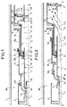
- the circuit breaker shown in partial view in FIG. 1 comprises a casing 1, of insulating material such as ceramic, of generally cylindrical shape with axis XX and delimiting an interior volume Vo filled with dielectric gas such as sulfur hexafluoride, under a pressure of a few bars.
- insulating material such as ceramic
- dielectric gas such as sulfur hexafluoride
- the circuit breaker comprises a fixed main contact 2 connected to a first socket not shown, and a fixed arcing contact 3, having one end 3A made of an alloy resistant to the effects of the arc, such as a tungsten alloy.
- the moving element of the circuit breaker comprises a tube 4, one end of which 4A, made of an arc-resistant alloy, constitutes the moving arcing contact.
- the tube 4 is connected, at its other end 4B, to an operating device, not shown.
- the tube 4 is integral with a tube 5, one end of which 5A constitutes the movable main contact of the circuit breaker.
- an insulating nozzle 6 At the end 5A is fixed an insulating nozzle 6, the neck of which is obstructed by the arcing contact 4 when the circuit breaker is in the closed position.
- Holes 7 are made in the crown connecting the tubes 4 and 5 so that these tubes define a single volume V1, closed on one side by the nozzle 6.
- the part 8 is connected to a second outlet not shown.
- the tube 5 which constitutes the blowing cylinder of the circuit breaker, is integral with a piston 14 placed inside the tube 88 and capable of sliding in this tube in leaktight manner thanks to a seal 14D.
- the piston 14 defines with the tubes 8A and 8B a volume V2.
- the piston has openings 14A which can be closed by an annular valve 16, the stroke of which is limited by a projection 14B.
- the tube 4 is pierced with very large openings 15 on its surface putting in communication by large passages the volume V2 with the volume V3 inside the tube 4. It is noted that the volume V3 is closed, on the operating member side by a disc 17 integral of tube 4.
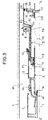
- the circuit breaker works as follows:
- the circuit breaker operating device drives the moving assembly (tubes 4 and 5, nozzle 6, piston 14) to the right of the figure.
- the main contacts separate and the current then flows through the arcing contacts 3 and 4.
- an arc 20 (fig.2) is formed; it strongly heats the surrounding gas and the pressure increases strongly.
- the volume V1 is closed by application of the valve 13.
- the hot gas escapes through the volume V3 surrounding the axis and passes through the openings 15 in the volume V2.
- the pressure prevailing in the volume V1 produces at the first zero crossing of the current an expansion of gas through the nozzle 6, which produces the extinction of the arc.
- the pressure in the volume V1 is sufficient to press the valve 13 against its seat; the expansion of volume V1 at zero current crossing is enough to cut the arc.
- the operating member moves the moving assembly to the right of the figure.
- a slight overpressure in the volume V2 causes the valve 16 to close on the one hand, and on the other hand, combined with a slight depression in the volume V1, causes the slide 11 to move to the left.
- the valve 13 opens, which allows filling of the volume V1 without requiring any particular effect due to a significant depression in the volume V1.
Landscapes
- Circuit Breakers (AREA)
- Pens And Brushes (AREA)
- Superconductors And Manufacturing Methods Therefor (AREA)
- Organic Insulating Materials (AREA)
- Gas-Insulated Switchgears (AREA)
- Emergency Protection Circuit Devices (AREA)
Claims (5)
- Hoch- und Mittelspannungstrennschalter mit Blasgas, der aufweist:- eine mit einem unter Druck stehenden dielektrischen Gas gefüllte zylindrische, isolierende Hülle,- einen ortsfesten Hauptkontakt (2),- einen ortsfesten Lichtbogenkontakt (3),- bewegliche Schaltorgane, die mit einem Betätigungsorgan verbunden sind und aufweisen:dadurch gekennzeichnet, daß- einen beweglichen Hauptkontakt (5A),- einen Blaszylinder (5), der einer Blasdüse (6) zugeordnet ist und mit einem ersten Kolben (13) zusammenwirkt,- einen zweiten fest mit den beweglichen Schaltorganen verbundenen Kolben (14), der in einem zweiten, ortsfesten, durch einen rohrförmigen Abschnitt (8A) fest mit dem ersten Kolben (13) verbundenen Zylinder (8B) gleitet und mit Mitteln (15) zur Herstellung einer Verbindung mit der Lichtbogenzone bei geringen Druckverlusten zusammenwirkt,- einen Lichtbogenkontakt, der aus einem ersten Ende (4A) eines Metallrohrs (4) besteht, das zum Trennschalter koaxial ist, während das zweite Ende des Rohrs mit dem Betätigungsorgan verbunden ist,- der zweite Zylinder (8B) einen größeren Durchmesser als der rohrförmige Abschnitt (8A) besitzt,- der Querschnitt des zweiten Kolbens (14, 17) wesentlich größer als der des ersten Kolbens (13) ist,- der zweite Kolben von kalibrierten Öffnungen (14C) zur Begrenzung des auf die Fläche des Kolbens einwirkenden Drucks durchquert wird, die die durch den Lichtbogen aufgeheizten Gase empfängt.
- Trennschalter nach Anspruch 1, dadurch gekennzeichnet, daß der zweite Kolben (14) ein das Rohr umgebender und fest mit ihm verbundener ringförmiger Kolben ist und die Mittel zur Herstellung einer Verbindung mit geringen Druckverlusten aus dem Rohr (4) bestehen, das an seinem Umfang große Öffnungen (15) besitzt, wobei das Innere des Rohres im wesentlichen in Höhe des Kolbens durch ein Bauteil (17) verschlossen ist.
- Trennschalter nach Anspruch 2, dadurch gekennzeichnet, daß der erste Kolben eine ringförmige Ventilklappe (13) aufweist, die einen das Rohr (4) umgebenden und koaxial zu diesem verlaufenden zylindrischen Schieber (11) verschließt, wobei der Schieber zwei Stellungen einnehmen kann, in denen er Durchlässe (10) im zweiten Zylinder (8B) schließen oder öffnen kann, die in das Volumen der angrenzenden Hülle (1) einmünden.
- Trennschalter nach Anspruch 3, dadurch gekennzeichnet, daß die Durchlässe (10) radiale Schächte sind.
- Trennschalter nach einem der Ansprüche 1 bis 4, dadurch gekennzeichnet, daß der zweite Kolben eine Ventilklappe (16) trägt, die sich schließt, wenn der Druck auf der der der Lichtbogenzone näheren Seite des zweiten Kolbens (14) größer als der Druck auf der anderen Seite ist.
Priority Applications (1)
| Application Number | Priority Date | Filing Date | Title |
|---|---|---|---|
| AT90100019T ATE102741T1 (de) | 1989-01-02 | 1990-01-02 | Druckgasschalter fuer hoch- und mittelspannung. |
Applications Claiming Priority (2)
| Application Number | Priority Date | Filing Date | Title |
|---|---|---|---|
| FR8900009A FR2641409B1 (fr) | 1989-01-02 | 1989-01-02 | Disjoncteur a haute et moyenne tension a gaz de soufflage |
| FR8900009 | 1989-01-02 |
Publications (3)
| Publication Number | Publication Date |
|---|---|
| EP0380907A1 EP0380907A1 (de) | 1990-08-08 |
| EP0380907B1 EP0380907B1 (de) | 1994-03-09 |
| EP0380907B2 true EP0380907B2 (de) | 1996-12-11 |
Family
ID=9377438
Family Applications (1)
| Application Number | Title | Priority Date | Filing Date |
|---|---|---|---|
| EP90100019A Expired - Lifetime EP0380907B2 (de) | 1989-01-02 | 1990-01-02 | Druckgasschalter für Hoch- und Mittelspannung |
Country Status (9)
| Country | Link |
|---|---|
| US (1) | US4983789A (de) |
| EP (1) | EP0380907B2 (de) |
| JP (1) | JP2655733B2 (de) |
| CN (1) | CN1016548B (de) |
| AT (1) | ATE102741T1 (de) |
| BR (1) | BR9000007A (de) |
| CA (1) | CA2006934C (de) |
| DE (1) | DE69007136T3 (de) |
| FR (1) | FR2641409B1 (de) |
Families Citing this family (11)
| Publication number | Priority date | Publication date | Assignee | Title |
|---|---|---|---|---|
| ATE115765T1 (de) * | 1991-04-12 | 1994-12-15 | Gec Alsthom T & D Ag | Druckgasschalter. |
| FR2679696B1 (fr) * | 1991-07-24 | 1993-09-24 | Alsthom Gec | Disjoncteur a haute et moyenne tension a gaz de soufflage. |
| ATE140100T1 (de) * | 1992-02-06 | 1996-07-15 | Gec Alsthom T & D Ag | Druckgasschalter |
| ATE388478T1 (de) † | 2002-09-24 | 2008-03-15 | Abb Schweiz Ag | Leistungsschalter |
| DE102007031948A1 (de) * | 2007-07-06 | 2009-01-08 | Siemens Ag | Schaltgeräteanordnung mit einem Abströmkanal |
| JP5482613B2 (ja) * | 2010-10-05 | 2014-05-07 | 株式会社日立製作所 | ガス遮断器 |
| WO2013175565A1 (ja) * | 2012-05-22 | 2013-11-28 | 三菱電機株式会社 | ガス遮断器 |
| FR3030869B1 (fr) * | 2014-12-19 | 2017-02-10 | Alstom Technology Ltd | Disjoncteur comprenant un capot d'echappement de gaz a ouverture obturable |
| CN106328430B (zh) * | 2016-08-25 | 2018-08-07 | 中国西电电气股份有限公司 | 一种串联压气室的灭弧室 |
| JP6818604B2 (ja) * | 2017-03-24 | 2021-01-20 | 株式会社日立製作所 | ガス遮断器 |
| WO2019024978A1 (en) * | 2017-07-31 | 2019-02-07 | General Electric Technology Gmbh | ELECTRIC SWITCH COMPRISING A ARC BLOWING UNIT |
Family Cites Families (10)
| Publication number | Priority date | Publication date | Assignee | Title |
|---|---|---|---|---|
| US2957063A (en) * | 1958-03-07 | 1960-10-18 | Westinghouse Electric Corp | Pumped-gas circuit interrupter |
| JPS5419054B2 (de) * | 1973-11-07 | 1979-07-12 | ||
| CH600538A5 (de) * | 1976-04-22 | 1978-06-15 | Bbc Brown Boveri & Cie | |
| JPS5372176A (en) * | 1976-12-10 | 1978-06-27 | Hitachi Ltd | Buffer type gas breaker |
| CH655611B (de) * | 1981-06-18 | 1986-04-30 | ||
| FR2576142B1 (fr) * | 1985-01-16 | 1987-12-24 | Alsthom Atlantique | Disjoncteur a haute tension, a gaz comprime, a energie de manoeuvre assistee par l'effet thermique de l'arc |
| FR2576144B1 (fr) * | 1985-01-16 | 1987-02-06 | Alsthom Atlantique | Disjoncteur a haute tension, a gaz comprime, a faible energie de manoeuvre |
| FR2596575B1 (fr) * | 1986-03-26 | 1988-05-20 | Alsthom | Disjoncteur a gaz dielectrique sous pression |
| FR2596574B1 (fr) * | 1986-04-01 | 1988-05-20 | Alsthom | Disjoncteur a haute tension a gaz dielectrique sous pression |
| JP2528100B2 (ja) * | 1986-07-08 | 1996-08-28 | 株式会社日立製作所 | パツフア形ガス遮断器 |
-
1989
- 1989-01-02 FR FR8900009A patent/FR2641409B1/fr not_active Expired - Fee Related
- 1989-12-28 JP JP1345125A patent/JP2655733B2/ja not_active Expired - Fee Related
- 1989-12-29 CA CA002006934A patent/CA2006934C/fr not_active Expired - Fee Related
- 1989-12-31 CN CN89109654A patent/CN1016548B/zh not_active Expired
-
1990
- 1990-01-02 EP EP90100019A patent/EP0380907B2/de not_active Expired - Lifetime
- 1990-01-02 AT AT90100019T patent/ATE102741T1/de not_active IP Right Cessation
- 1990-01-02 BR BR909000007A patent/BR9000007A/pt not_active IP Right Cessation
- 1990-01-02 US US07/459,893 patent/US4983789A/en not_active Expired - Lifetime
- 1990-01-02 DE DE69007136T patent/DE69007136T3/de not_active Expired - Fee Related
Also Published As
| Publication number | Publication date |
|---|---|
| FR2641409A1 (fr) | 1990-07-06 |
| EP0380907B1 (de) | 1994-03-09 |
| US4983789A (en) | 1991-01-08 |
| DE69007136T3 (de) | 1997-03-06 |
| FR2641409B1 (fr) | 1996-04-26 |
| CA2006934A1 (fr) | 1990-07-02 |
| CN1016548B (zh) | 1992-05-06 |
| EP0380907A1 (de) | 1990-08-08 |
| JPH02230625A (ja) | 1990-09-13 |
| DE69007136T2 (de) | 1994-06-16 |
| JP2655733B2 (ja) | 1997-09-24 |
| DE69007136D1 (de) | 1994-04-14 |
| CN1044008A (zh) | 1990-07-18 |
| CA2006934C (fr) | 1994-04-26 |
| BR9000007A (pt) | 1990-10-09 |
| ATE102741T1 (de) | 1994-03-15 |
Similar Documents
| Publication | Publication Date | Title |
|---|---|---|
| EP0380907B2 (de) | Druckgasschalter für Hoch- und Mittelspannung | |
| EP0441292B1 (de) | Mittelspannungsschalter mit Selbstbeblasung | |
| EP0591039B1 (de) | Hochspannung selbst-Blaslastscharter mit Schnittkammer mit reduzierter Gaskompression | |
| EP0367072B1 (de) | Hochspannungsdruckgasschalter | |
| CA2074893C (fr) | Disjoncteur a moyenne ou haute tension a contacts d'arc en bout | |
| EP0302390B1 (de) | Druckgasschalter für Hoch- oder Mittelspannung mit von der Lichtbogenenergie entnommener Ausschaltenergie | |
| CA2014512C (fr) | Disjoncteur a moyenne tension a gaz de soufflage | |
| FR2576144A1 (fr) | Disjoncteur a haute tension, a gaz comprime, a faible energie de manoeuvre | |
| EP0334181B1 (de) | Hochspannungsschalter mit geringer Antriebsenergie | |
| EP0239932A1 (de) | Hochspannungsdruckgaslastschalter | |
| EP0398211B1 (de) | Hochspannungs-Lastschalter mit dielektrischem Löschgas | |
| EP0415098B1 (de) | Selbstblasschalter für Mittelspannung | |
| EP0759629B1 (de) | Lastschalter mit Einschaltwiderstand und Einfügungsvorrichtung | |
| EP0359224A1 (de) | Hochspannungsschalter mit gasförmigem Dielektrikum zum Beblasen | |
| CA2017127C (fr) | Disjoncteur a moyenne tension a courant nominal eleve | |
| EP0406794B1 (de) | Hoch- oder Mittelspannungslastschalter | |
| EP0456025B1 (de) | Hochspannungsschalter mit Hilfslichtbogen in Reihe | |
| EP0400523B1 (de) | Hochspannungs-Lastschalter mit gasförmigem Dielektrikum zum Beblasen | |
| FR2535518A1 (fr) | Chambre de coupure pour disjoncteur a gaz | |
| EP0398116B1 (de) | Mittelspannungsschalter mit Selbstbeblasung | |
| FR2705494A1 (fr) | Disjoncteur à manÓoeuvre assistée par voie électrodynamique. | |
| FR2729788A1 (fr) | Disjoncteur a haute tension a gaz de soufflage | |
| CH688702A5 (fr) | Disjoncteur à haute tension ayant une chambre de coupure à volume de soufflage variable. | |
| FR2646961A1 (fr) | Disjoncteur a moyenne tension a autosoufflage | |
| CH689884A5 (fr) | Disjoncteur à ouverture assistée par effet électronique-dynamique. |
Legal Events
| Date | Code | Title | Description |
|---|---|---|---|
| PUAI | Public reference made under article 153(3) epc to a published international application that has entered the european phase |
Free format text: ORIGINAL CODE: 0009012 |
|
| AK | Designated contracting states |
Kind code of ref document: A1 Designated state(s): AT BE CH DE DK ES FR GB GR IT LI LU NL SE |
|
| 17P | Request for examination filed |
Effective date: 19910204 |
|
| 17Q | First examination report despatched |
Effective date: 19930319 |
|
| GRAA | (expected) grant |
Free format text: ORIGINAL CODE: 0009210 |
|
| AK | Designated contracting states |
Kind code of ref document: B1 Designated state(s): AT BE CH DE DK ES FR GB GR IT LI LU NL SE |
|
| PG25 | Lapsed in a contracting state [announced via postgrant information from national office to epo] |
Ref country code: NL Effective date: 19940309 Ref country code: GR Free format text: LAPSE BECAUSE OF FAILURE TO SUBMIT A TRANSLATION OF THE DESCRIPTION OR TO PAY THE FEE WITHIN THE PRESCRIBED TIME-LIMIT Effective date: 19940309 Ref country code: ES Free format text: THE PATENT HAS BEEN ANNULLED BY A DECISION OF A NATIONAL AUTHORITY Effective date: 19940309 Ref country code: DK Effective date: 19940309 Ref country code: AT Effective date: 19940309 |
|
| REF | Corresponds to: |
Ref document number: 102741 Country of ref document: AT Date of ref document: 19940315 Kind code of ref document: T |
|
| REF | Corresponds to: |
Ref document number: 69007136 Country of ref document: DE Date of ref document: 19940414 |
|
| GBT | Gb: translation of ep patent filed (gb section 77(6)(a)/1977) |
Effective date: 19940321 |
|
| ITF | It: translation for a ep patent filed | ||
| NLV1 | Nl: lapsed or annulled due to failure to fulfill the requirements of art. 29p and 29m of the patents act | ||
| PLBI | Opposition filed |
Free format text: ORIGINAL CODE: 0009260 |
|
| EAL | Se: european patent in force in sweden |
Ref document number: 90100019.0 |
|
| PG25 | Lapsed in a contracting state [announced via postgrant information from national office to epo] |
Ref country code: LU Free format text: LAPSE BECAUSE OF NON-PAYMENT OF DUE FEES Effective date: 19950131 Ref country code: BE Effective date: 19950131 |
|
| 26 | Opposition filed |
Opponent name: ABB MANAGEMENT AG, BADEN TEI/IMMATERIALGUETERRECHT Effective date: 19941206 |
|
| BERE | Be: lapsed |
Owner name: S.A. GEC ALSTHOM Effective date: 19950131 |
|
| PLAW | Interlocutory decision in opposition |
Free format text: ORIGINAL CODE: EPIDOS IDOP |
|
| PLAW | Interlocutory decision in opposition |
Free format text: ORIGINAL CODE: EPIDOS IDOP |
|
| PUAH | Patent maintained in amended form |
Free format text: ORIGINAL CODE: 0009272 |
|
| STAA | Information on the status of an ep patent application or granted ep patent |
Free format text: STATUS: PATENT MAINTAINED AS AMENDED |
|
| 27A | Patent maintained in amended form |
Effective date: 19961211 |
|
| AK | Designated contracting states |
Kind code of ref document: B2 Designated state(s): AT BE CH DE DK ES FR GB GR IT LI LU NL SE |
|
| ITF | It: translation for a ep patent filed | ||
| REG | Reference to a national code |
Ref country code: CH Ref legal event code: AEN Free format text: MAINTIEN DU BREVET DONT L'ETENDUE A ETE MODIFIEE |
|
| GBTA | Gb: translation of amended ep patent filed (gb section 77(6)(b)/1977) | ||
| REG | Reference to a national code |
Ref country code: GB Ref legal event code: IF02 |
|
| PGFP | Annual fee paid to national office [announced via postgrant information from national office to epo] |
Ref country code: SE Payment date: 20040105 Year of fee payment: 15 Ref country code: GB Payment date: 20040105 Year of fee payment: 15 |
|
| PGFP | Annual fee paid to national office [announced via postgrant information from national office to epo] |
Ref country code: CH Payment date: 20040106 Year of fee payment: 15 |
|
| PGFP | Annual fee paid to national office [announced via postgrant information from national office to epo] |
Ref country code: DE Payment date: 20040108 Year of fee payment: 15 |
|
| PGFP | Annual fee paid to national office [announced via postgrant information from national office to epo] |
Ref country code: FR Payment date: 20040109 Year of fee payment: 15 |
|
| REG | Reference to a national code |
Ref country code: CH Ref legal event code: PFA Owner name: ALSTOM HOLDINGS Free format text: ALSTOM FRANCE S.A.#38, AVENUE KLEBER#75116 PARIS (FR) -TRANSFER TO- ALSTOM HOLDINGS#25, AVENUE KLEBER#75116 PARIS (FR) Ref country code: CH Ref legal event code: PFA Owner name: ALSTOM FRANCE S.A. Free format text: GEC ALSTHOM S.A.#38, AVENUE KLEBER#PARIS (FR) -TRANSFER TO- ALSTOM FRANCE S.A.#38, AVENUE KLEBER#75116 PARIS (FR) |
|
| PG25 | Lapsed in a contracting state [announced via postgrant information from national office to epo] |
Ref country code: IT Free format text: LAPSE BECAUSE OF NON-PAYMENT OF DUE FEES;WARNING: LAPSES OF ITALIAN PATENTS WITH EFFECTIVE DATE BEFORE 2007 MAY HAVE OCCURRED AT ANY TIME BEFORE 2007. THE CORRECT EFFECTIVE DATE MAY BE DIFFERENT FROM THE ONE RECORDED. Effective date: 20050102 Ref country code: GB Free format text: LAPSE BECAUSE OF NON-PAYMENT OF DUE FEES Effective date: 20050102 |
|
| PG25 | Lapsed in a contracting state [announced via postgrant information from national office to epo] |
Ref country code: SE Free format text: LAPSE BECAUSE OF NON-PAYMENT OF DUE FEES Effective date: 20050103 |
|
| PG25 | Lapsed in a contracting state [announced via postgrant information from national office to epo] |
Ref country code: LI Free format text: LAPSE BECAUSE OF NON-PAYMENT OF DUE FEES Effective date: 20050131 Ref country code: CH Free format text: LAPSE BECAUSE OF NON-PAYMENT OF DUE FEES Effective date: 20050131 |
|
| REG | Reference to a national code |
Ref country code: FR Ref legal event code: CD |
|
| REG | Reference to a national code |
Ref country code: FR Ref legal event code: CD |
|
| PG25 | Lapsed in a contracting state [announced via postgrant information from national office to epo] |
Ref country code: DE Free format text: LAPSE BECAUSE OF NON-PAYMENT OF DUE FEES Effective date: 20050802 |
|
| GBPC | Gb: european patent ceased through non-payment of renewal fee |
Effective date: 20050102 |
|
| EUG | Se: european patent has lapsed | ||
| REG | Reference to a national code |
Ref country code: CH Ref legal event code: PL |
|
| PG25 | Lapsed in a contracting state [announced via postgrant information from national office to epo] |
Ref country code: FR Free format text: LAPSE BECAUSE OF NON-PAYMENT OF DUE FEES Effective date: 20050930 |
|
| REG | Reference to a national code |
Ref country code: FR Ref legal event code: ST |