EP0380791A2 - Dispositif à gestion automatique de parties de matériaux continus - Google Patents
Dispositif à gestion automatique de parties de matériaux continus Download PDFInfo
- Publication number
- EP0380791A2 EP0380791A2 EP89122876A EP89122876A EP0380791A2 EP 0380791 A2 EP0380791 A2 EP 0380791A2 EP 89122876 A EP89122876 A EP 89122876A EP 89122876 A EP89122876 A EP 89122876A EP 0380791 A2 EP0380791 A2 EP 0380791A2
- Authority
- EP
- European Patent Office
- Prior art keywords
- work table
- web
- flat material
- movement
- feed position
- Prior art date
- Legal status (The legal status is an assumption and is not a legal conclusion. Google has not performed a legal analysis and makes no representation as to the accuracy of the status listed.)
- Granted
Links
- 238000006073 displacement reaction Methods 0.000 claims abstract description 9
- 238000003860 storage Methods 0.000 claims description 2
- 238000005520 cutting process Methods 0.000 description 2
- 238000010276 construction Methods 0.000 description 1
- 238000004519 manufacturing process Methods 0.000 description 1
- 238000000034 method Methods 0.000 description 1
Images
Classifications
-
- G—PHYSICS
- G06—COMPUTING; CALCULATING OR COUNTING
- G06K—GRAPHICAL DATA READING; PRESENTATION OF DATA; RECORD CARRIERS; HANDLING RECORD CARRIERS
- G06K15/00—Arrangements for producing a permanent visual presentation of the output data, e.g. computer output printers
- G06K15/22—Arrangements for producing a permanent visual presentation of the output data, e.g. computer output printers using plotters
Definitions
- the invention relates to an automatically controlled device for the section-wise treatment of a web made of flat material, which is spread out on the support surface of a work table, which is shorter than the web, with a control in the direction of the longitudinal extension of the web over the support surface of the work table. and movable carriage, on which a head, which can be moved back and forth transversely to the longitudinal extension of the web, for holding a tool, is arranged, and with a device for the partial displacement of the flat material from a storage area to the front in the direction of the longitudinal extension of the web.
- the device for the gradual displacement of the flat material consists of clamping elements which are attached to the slide are and which can be brought into clamping engagement with the edge region of the sheet of flat material in order in this way to shift the flat material by controlled movement of the slide a precisely defined distance, so that the flat material according to Freigae lies on the support surface of the work table in such a way that the records or incisions that are initially located at the rear end of the work table are now located at a precisely defined location on the front end of the support surface.
- the tool can then continue the treatment of the flat material in such a way that the new recordings or incisions closely follow the recordings or incisions previously made.
- the carriage carrying the head for receiving the tool is thus additionally equipped with the clamping elements, as a result of which its construction is relatively complicated and its weight is high. Therefore, the production is expensive and high demands are made on the drive and control devices for the slide.
- a device of the type mentioned at the outset is designed according to the invention in such a way that the work table in the direction of the longitudinal extent of the web between a working position for treating the flat material and a feed position offset in the direction of displacement can be moved back and forth, the length of the support surface of the work table being greater than the length of the path of movement of the work table between the work position and the feed position, so that the flat material has a relative movement at least during the movement of the work table from the work position to the feed position between them is connected to the work table and that a web holding device is provided in the area of the frame supporting the work table that is adjacent to the front edge of the work table in the feed position, which means that the flat material cannot be displaced with respect to the movement of the work table from the feed position to the work position Frame holds.
- the section-wise displacement of the sheet of flat material thus takes place in a controlled and defined manner in that after treatment of a section located on the support surface of the work table, the sheet is moved together with the work table into the feed position, in which the sheet is then moved by means of The web holding device is positioned so that it cannot be displaced, while the work table is moved back into the working position without the web being displaced.
- a precisely defined displacement movement of the flat material has taken place, so that the recordings or incisions previously made, located in the rear area of the support surface of the work table, are now at a known location in the front area of the support surface and the treatment by means of the tool with precise connection can continue to the previously made records or cuts.
- the web holding device can have a clamping bar which can be pressed against a bearing surface of the frame and which, in the pressed position, holds the web of flat material in such a way that it cannot be displaced with respect to the frame, while in the raised position the flat material can be displaced, i.e. the movement of the work table from the working position to the Feed position and thus the corresponding shifting of the web can take place.
- the work table can have forward-extending support projections at the front end that extend the support surface and, in the feed position, extend into recesses provided in the contact surface.
- the support of the flat material by the work table extends into the area of the support surface in the feed position, so that possible displacements of the flat material are avoided when the clamping bar is pressed onto the contact surface.
- the work table can be provided with a web suction device which is activated at least immediately before and during the movement of the work table from the work position to the feed position and which during the movement from the feed position to the work position is ineffective.
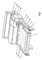
- the device shown has a frame 1, on which an idling guide roller 4 is arranged at one end, with respect to which guide plates 2 extending laterally and with their longitudinal extensions perpendicular to the central axis of the guide roller 4 are attached.
- a work table 10 is arranged on the frame 1, which has a support surface 11, in which suction openings 15 are formed, which are connected in a manner not shown to a pump generating a vacuum.
- this support projections 14 are notched, and the function of the support projections 14 will be described later.
- a carriage 20 is mounted, which extends across the work table 10 and can be moved back and forth in a controlled manner in the direction perpendicular to the longitudinal axis of the guide roller 4 over the support surface 11 of the work table 10, as is known per se and for example for so-called Flat plotter is common.
- a head 21 can be moved back and forth in a controlled manner parallel to the longitudinal axis of the guide roller 4 and carries a receptacle 22 for a tool, for example a cutting tool or a plotter cone.
- a bar 3 which in its upper surface has cutouts 5 in an indicated manner, the dimensions of which correspond to the dimensions of the support projections 14 of the work table 10.
- a clamping bar 30 which can be moved back and forth in the vertical direction and which can be lowered onto the upper surface of the bar 3 for the clamping support.
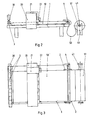
- a supply roll 51 with flat material wound on a carrier roller 41 is held in receptacles 40 adjacent to the guide roller 4 (FIG. 2), and the web 50 is guided over the guide roller 4 and laterally by the guide plates 2 with one section brought to the support surface 11 of the work table 10. If necessary, it is pulled firmly against the bearing surface 11 by applying a vacuum to the suction openings 15. In this state, the desired path course can be recorded on or into the section of the path 50 located on the support surface 11 of the work table 10 by controlled back and forth movements of the slide 20 and the head 21 Web to be cut.
- the clamping bar 30 When the feed position is reached, the clamping bar 30 is lowered and brought into engagement with the area of the web 50 located below it, so that it is pressed against the upper surface of the bar 3 and held in this position. Now the negative pressure applied to the suction openings 15 is switched off, and the work table 10 is moved back into the working position shown in the figures, while the web 50 is not displaced with respect to the frame 1. In the working position of the work table 10, negative pressure can then again be applied to the suction openings 15 and the section of the web 50 that is now to be machined and located on the support surface 11 of the work table 10 can be machined.
Landscapes
- Engineering & Computer Science (AREA)
- General Engineering & Computer Science (AREA)
- Physics & Mathematics (AREA)
- General Physics & Mathematics (AREA)
- Theoretical Computer Science (AREA)
- Replacement Of Web Rolls (AREA)
- Treatment Of Fiber Materials (AREA)
- Processing And Handling Of Plastics And Other Materials For Molding In General (AREA)
- Machines For Laying And Maintaining Railways (AREA)
- Finish Polishing, Edge Sharpening, And Grinding By Specific Grinding Devices (AREA)
- Folding Of Thin Sheet-Like Materials, Special Discharging Devices, And Others (AREA)
- Advancing Webs (AREA)
Priority Applications (1)
| Application Number | Priority Date | Filing Date | Title |
|---|---|---|---|
| AT89122876T ATE92623T1 (de) | 1988-12-24 | 1989-12-12 | Automatisch gesteuerte vorrichtung fuer die abschnittsweise behandlung einer bahn aus flachmaterial. |
Applications Claiming Priority (2)
| Application Number | Priority Date | Filing Date | Title |
|---|---|---|---|
| DE3843868A DE3843868C1 (fr) | 1988-12-24 | 1988-12-24 | |
| DE3843868 | 1988-12-24 |
Publications (3)
| Publication Number | Publication Date |
|---|---|
| EP0380791A2 true EP0380791A2 (fr) | 1990-08-08 |
| EP0380791A3 EP0380791A3 (fr) | 1991-12-04 |
| EP0380791B1 EP0380791B1 (fr) | 1993-08-04 |
Family
ID=6370242
Family Applications (1)
| Application Number | Title | Priority Date | Filing Date |
|---|---|---|---|
| EP89122876A Expired - Lifetime EP0380791B1 (fr) | 1988-12-24 | 1989-12-12 | Dispositif à gestion automatique de parties de matériaux continus |
Country Status (4)
| Country | Link |
|---|---|
| EP (1) | EP0380791B1 (fr) |
| AT (1) | ATE92623T1 (fr) |
| DE (2) | DE3843868C1 (fr) |
| ES (1) | ES2044035T3 (fr) |
Cited By (1)
| Publication number | Priority date | Publication date | Assignee | Title |
|---|---|---|---|---|
| CN114852739A (zh) * | 2022-05-17 | 2022-08-05 | 宜昌佳艺包装有限责任公司 | 酒瓶口装饰丝带印刷的批量放卷装置及方法 |
Citations (4)
| Publication number | Priority date | Publication date | Assignee | Title |
|---|---|---|---|---|
| US4483472A (en) * | 1983-03-01 | 1984-11-20 | Gerber Scientific Inc. | Apparatus and method for indexing sheet material |
| GB2147884A (en) * | 1983-09-09 | 1985-05-22 | Dainippon Screen Mfg | Coordinate plotter with automatic punching device |
| US4568075A (en) * | 1984-11-08 | 1986-02-04 | Eastman Kodak Company | Sheet registration and clamping apparatus |
| GB2177067A (en) * | 1985-05-31 | 1987-01-14 | Cybrid Ltd | Web feeding means |
Family Cites Families (1)
| Publication number | Priority date | Publication date | Assignee | Title |
|---|---|---|---|---|
| US3844461A (en) * | 1973-04-09 | 1974-10-29 | Gerber Scientific Instr Co | Precise indexing apparatus and method |
-
1988
- 1988-12-24 DE DE3843868A patent/DE3843868C1/de not_active Expired - Fee Related
-
1989
- 1989-12-12 ES ES89122876T patent/ES2044035T3/es not_active Expired - Lifetime
- 1989-12-12 EP EP89122876A patent/EP0380791B1/fr not_active Expired - Lifetime
- 1989-12-12 DE DE8989122876T patent/DE58905170D1/de not_active Expired - Fee Related
- 1989-12-12 AT AT89122876T patent/ATE92623T1/de not_active IP Right Cessation
Patent Citations (4)
| Publication number | Priority date | Publication date | Assignee | Title |
|---|---|---|---|---|
| US4483472A (en) * | 1983-03-01 | 1984-11-20 | Gerber Scientific Inc. | Apparatus and method for indexing sheet material |
| GB2147884A (en) * | 1983-09-09 | 1985-05-22 | Dainippon Screen Mfg | Coordinate plotter with automatic punching device |
| US4568075A (en) * | 1984-11-08 | 1986-02-04 | Eastman Kodak Company | Sheet registration and clamping apparatus |
| GB2177067A (en) * | 1985-05-31 | 1987-01-14 | Cybrid Ltd | Web feeding means |
Cited By (2)
| Publication number | Priority date | Publication date | Assignee | Title |
|---|---|---|---|---|
| CN114852739A (zh) * | 2022-05-17 | 2022-08-05 | 宜昌佳艺包装有限责任公司 | 酒瓶口装饰丝带印刷的批量放卷装置及方法 |
| CN114852739B (zh) * | 2022-05-17 | 2024-02-02 | 宜昌佳艺包装有限责任公司 | 酒瓶口装饰丝带印刷的批量放卷装置及方法 |
Also Published As
| Publication number | Publication date |
|---|---|
| ES2044035T3 (es) | 1994-01-01 |
| DE3843868C1 (fr) | 1990-05-10 |
| DE58905170D1 (de) | 1993-09-09 |
| EP0380791B1 (fr) | 1993-08-04 |
| ATE92623T1 (de) | 1993-08-15 |
| EP0380791A3 (fr) | 1991-12-04 |
Similar Documents
| Publication | Publication Date | Title |
|---|---|---|
| DE1942410C3 (de) | Maschine zum Fertigen von Beuteln aus einer thermoplastischen Folienbahn | |
| DE3724321B4 (de) | Zweischnitt-Bandsägemaschine | |
| DE3034621A1 (de) | Verfahren und schneidvorrichtung zur herstellung von zuschnitten | |
| EP0046910A1 (fr) | Machine de traitement à installation thermique de jet de coupage, notamment installation de jet de coupage à plasma | |
| EP0509188B1 (fr) | Machine-outil à usiner des plaques | |
| DE2708457A1 (de) | Transportmechanismus zur verwendung in schmiedemaschinen | |
| DE1552613A1 (de) | Einspannvorrichtung fuer Band- und Streifenmaterial | |
| DE2205107A1 (de) | Bearbeitungsvorrichtung von Werk stucken | |
| EP0505668B1 (fr) | Table de travail à vide | |
| DE4090853B4 (de) | Schnitteilstück-Transportvorrichtung für eine Schneidemaschine | |
| DE2656745A1 (de) | Montagevorrichtung | |
| DE2425101B2 (de) | Verfahren und Vorrichtung zum Herstellen elektrischer Kontaktelemente | |
| EP0380791B1 (fr) | Dispositif à gestion automatique de parties de matériaux continus | |
| DE2704415A1 (de) | Bohrmaschine, insbesondere fuer die holzverarbeitung | |
| DE3109226A1 (de) | Verfahren zum schneiden mit einem handgefuehrten schneidwerkzeug | |
| DE8518255U1 (de) | Stütz- und Transportvorrichtung für flächige Werkstücke | |
| DE102016120139B4 (de) | Verfahren, Werkzeugmaschine und Schlitzwerkzeug zum mehrhubig fortschreitenden Schlitzen von plattenförmigen Werkstücken | |
| WO1984002451A1 (fr) | Procede d'usinage et/ou de manipulation de materiau plat | |
| DE2048079C3 (de) | Verfahren und Vorrichtung zum Kaltverschweißen (Festkörperverschweißung) zweier Werkstücke | |
| DE2152518A1 (de) | Vorrichtung mit Taster zum Abschneiden von Rohrabschnitten von einem fortlaufend hergestellten Rohr | |
| EP0362833A2 (fr) | Machine de travail du bois, de préférence une moulurière | |
| DE2556965A1 (de) | Kopiervorrichtung in form eines kopierarms, pantographen o.dgl. | |
| EP0384136A2 (fr) | Dispositif automatique pour le traitement pas à pas d'une bande de matériau plat | |
| DE3546859C2 (de) | Niederhaltevorrichtung für eine Maschinenschere | |
| DE3108337A1 (de) | Strangpressmaschine und verfahren zum betrieb einer strangpressmaschine |
Legal Events
| Date | Code | Title | Description |
|---|---|---|---|
| PUAI | Public reference made under article 153(3) epc to a published international application that has entered the european phase |
Free format text: ORIGINAL CODE: 0009012 |
|
| AK | Designated contracting states |
Kind code of ref document: A2 Designated state(s): AT BE CH DE ES FR GB GR IT LI LU NL SE |
|
| 17P | Request for examination filed |
Effective date: 19901231 |
|
| PUAL | Search report despatched |
Free format text: ORIGINAL CODE: 0009013 |
|
| AK | Designated contracting states |
Kind code of ref document: A3 Designated state(s): AT BE CH DE ES FR GB GR IT LI LU NL SE |
|
| 17Q | First examination report despatched |
Effective date: 19921218 |
|
| GRAA | (expected) grant |
Free format text: ORIGINAL CODE: 0009210 |
|
| AK | Designated contracting states |
Kind code of ref document: B1 Designated state(s): AT BE CH DE ES FR GB GR IT LI LU NL SE |
|
| PG25 | Lapsed in a contracting state [announced via postgrant information from national office to epo] |
Ref country code: SE Effective date: 19930804 Ref country code: NL Effective date: 19930804 Ref country code: GR Free format text: LAPSE BECAUSE OF FAILURE TO SUBMIT A TRANSLATION OF THE DESCRIPTION OR TO PAY THE FEE WITHIN THE PRESCRIBED TIME-LIMIT Effective date: 19930804 Ref country code: GB Effective date: 19930804 |
|
| REF | Corresponds to: |
Ref document number: 92623 Country of ref document: AT Date of ref document: 19930815 Kind code of ref document: T |
|
| REF | Corresponds to: |
Ref document number: 58905170 Country of ref document: DE Date of ref document: 19930909 |
|
| ET | Fr: translation filed | ||
| ITF | It: translation for a ep patent filed | ||
| PG25 | Lapsed in a contracting state [announced via postgrant information from national office to epo] |
Ref country code: AT Effective date: 19931212 |
|
| PG25 | Lapsed in a contracting state [announced via postgrant information from national office to epo] |
Ref country code: LU Free format text: LAPSE BECAUSE OF NON-PAYMENT OF DUE FEES Effective date: 19931231 Ref country code: LI Effective date: 19931231 Ref country code: CH Effective date: 19931231 Ref country code: BE Effective date: 19931231 |
|
| REG | Reference to a national code |
Ref country code: ES Ref legal event code: FG2A Ref document number: 2044035 Country of ref document: ES Kind code of ref document: T3 |
|
| NLV1 | Nl: lapsed or annulled due to failure to fulfill the requirements of art. 29p and 29m of the patents act | ||
| GBV | Gb: ep patent (uk) treated as always having been void in accordance with gb section 77(7)/1977 [no translation filed] |
Effective date: 19930804 |
|
| PLBE | No opposition filed within time limit |
Free format text: ORIGINAL CODE: 0009261 |
|
| STAA | Information on the status of an ep patent application or granted ep patent |
Free format text: STATUS: NO OPPOSITION FILED WITHIN TIME LIMIT |
|
| BERE | Be: lapsed |
Owner name: ARISTO GRAPHIC SYSTEME G.M.B.H. & CO. K.G. Effective date: 19931231 |
|
| 26N | No opposition filed | ||
| PG25 | Lapsed in a contracting state [announced via postgrant information from national office to epo] |
Ref country code: FR Effective date: 19940831 |
|
| REG | Reference to a national code |
Ref country code: CH Ref legal event code: PL |
|
| PG25 | Lapsed in a contracting state [announced via postgrant information from national office to epo] |
Ref country code: DE Effective date: 19940901 |
|
| REG | Reference to a national code |
Ref country code: FR Ref legal event code: ST |
|
| PG25 | Lapsed in a contracting state [announced via postgrant information from national office to epo] |
Ref country code: ES Free format text: LAPSE BECAUSE OF NON-PAYMENT OF DUE FEES Effective date: 19941213 |
|
| EUG | Se: european patent has lapsed |
Ref document number: 89122876.9 Effective date: 19931209 |
|
| REG | Reference to a national code |
Ref country code: ES Ref legal event code: FD2A Effective date: 19950112 |
|
| PG25 | Lapsed in a contracting state [announced via postgrant information from national office to epo] |
Ref country code: IT Free format text: LAPSE BECAUSE OF NON-PAYMENT OF DUE FEES;WARNING: LAPSES OF ITALIAN PATENTS WITH EFFECTIVE DATE BEFORE 2007 MAY HAVE OCCURRED AT ANY TIME BEFORE 2007. THE CORRECT EFFECTIVE DATE MAY BE DIFFERENT FROM THE ONE RECORDED. Effective date: 20051212 |