EP0380681A1 - Dispositif de magnetotherapie - Google Patents
Dispositif de magnetotherapie Download PDFInfo
- Publication number
- EP0380681A1 EP0380681A1 EP89905824A EP89905824A EP0380681A1 EP 0380681 A1 EP0380681 A1 EP 0380681A1 EP 89905824 A EP89905824 A EP 89905824A EP 89905824 A EP89905824 A EP 89905824A EP 0380681 A1 EP0380681 A1 EP 0380681A1
- Authority
- EP
- European Patent Office
- Prior art keywords
- magnetic field
- output
- input
- inductor
- pulse
- Prior art date
- Legal status (The legal status is an assumption and is not a legal conclusion. Google has not performed a legal analysis and makes no representation as to the accuracy of the status listed.)
- Granted
Links
Images


Classifications
-
- A—HUMAN NECESSITIES
- A61—MEDICAL OR VETERINARY SCIENCE; HYGIENE
- A61N—ELECTROTHERAPY; MAGNETOTHERAPY; RADIATION THERAPY; ULTRASOUND THERAPY
- A61N2/00—Magnetotherapy
- A61N2/02—Magnetotherapy using magnetic fields produced by coils, including single turn loops or electromagnets
Definitions
- the present invention relates to medicine and relates in particular to a device for magnetotherapy.
- a device for magnetotherapy which, when connected in series, contains a current pulse generator, an energy store and a discharge circuit for the latter, the discharge circuit having a controllable switching element and an inductor by means of which a healing implus magnetic field can be generated.
- the device contains a unit for controlling the magnetic field pulse duration of the inductor, the output of which is connected to the control input of the switching element (SU, A, 1321426).
- the known device is intended for anesthesia in the case of radiculitis, plexitis and other diseases and for controlling the displacement of X-ray contrast media in the patient's organism.
- the doctor selects the most suitable amplitude and duration of the impulses of a healing magnetic field of the inductor and a number of treatment steps during which the patient is acted on with the magnetic field.
- the time required to select the optimal parameters of magnetic pulses is usually at least 3 to 7 minutes.
- fluctuations in the characteristics of the structural units of the device e.g. B. possible by their heating, amplitude jumps and magnetic field pulses, including values that exceed the permissible value.
- a device for magnetotherapy which - connected in series - contains a controllable current pulse generator, an energy store and a discharge circuit for the latter, which has a controllable switching element and an inductor, by means of which a healing pulse magnetic field can be generated, and which one Unit for controlling the magnetic field pulse inductor, the output of which is connected to the control input of the switching element, and a magnetic field pulse amplitude controller, the output of which is connected to the control input of the pulse generator (EP, B, 0043451).
- the amplitude controller of this device ensures that the peak values of the amplitude of the magnetic field impluse are limited.
- the selection of the parameters of the pulses of a healing magnetic field that are optimal for the patient is carried out by using the latter device by varying the values of the pulse amplitude and duration for a longer time, which takes a considerable time and does not prove to be effective in all cases.
- the selection of the optimal parameters with the aid of the known device for the docking of an acute painful syndrome, phantom pain, bronchial asthma attacks proves to be complicated
- the invention has for its object to perfect the device for magnetotherapy so that it has means for selecting the parameters and shape of the impulses of a healing magnetic field, which the cropping of an acute painful syndrome, phantom pain, bronchial asthma attacks for a specific patient in as possible secure short periods.
- the essence of the invention is that in the device for magnetotherapy, which - connected in series - contains a controllable current pulse generator, an energy store and a discharge circuit for the same, which has a controllable switching element and an inductor through which a healing pulse magnetic field can be generated , and which is provided with a unit for controlling the magnetic field pulse duration of the inductor, the output of which is connected to the control input of the switching element, and a magnetic field amplitude controller, the output of which is connected to the control input of the pulse generator, according to the invention into the discharge circuit of the energy store Control section is switched for the leading edge steepness of the magnetic field pulses of the inductor.
- the control part for the steepness of the front surface of the magnetic field pulses of the inductor can be connected between the output of the energy store and the input of the switching element and can contain at least two LC chains, one of the connection ends of which are interconnected, and a selector switch whose normally closed contacts with the other connection ends of the corresponding LC Chains are connected.
- the control section for the leading edge steepness of the magnetic field pulses can be constructively combined with it, for which purpose the winding of the inductance coil must be provided with a large number of branches along the length of the winding conductor and the coil to the output of the switching element via one A wall switch is to be connected, of which each normally closed contact is connected to the associated A branch.
- the magnetic field pulse amplitude controller contains a comparison circuit, the first input of which is at the output of a magnetic field pulse amplitude generator, the second input is at the output of a magnetic field pulse amplitude adjuster and its output are connected to the output of the magnetic field pulse amplitude controller, additionally introduce a memory unit connected between the output of the magnetic field pulse amplitude transmitter and the first input of the comparative circuit and a second comparison circuit, the first input of which is connected to the output of the first comparison circuit, the second input is connected to the output via a voltage divider of the energy store and their output are connected to the output of the amplitude controller.
- the inventive device for By selecting an optimal value of the leading edge rise time of the impulse of a healing magnetic field, Magne to therapie offers the possibility of docking an acute painful syndrome, Fhanton pain, an attack of bronchial stress during the first three minutes from the beginning of the action.
- the use of the device according to the invention guarantees the maintenance of the pain-numbing effect within 6 to 12 hours after the cessation of magnetotherapy.
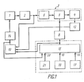
- the device for magnetotherapy shown in FIG. 1 contains - connected in series - a controllable current pulse generator 1, an energy store 2 and a discharge circuit 3 for the store 2.
- the discharge circuit 3 has an inductor 4 and a control part 6 connected to the input of the latter via a controllable switching element 5 for the leading edge steepness of the magnetic field pulses of the inductor, the input of which in turn lies at the output of the energy store 2.
- the device for magnetotherapy is also provided with a unit Z for controlling the magnetic field pulse duration, the output of which is connected via a power amplifier 8 to the control input of the switching element 5 and to the input 9 of a magnetic field pulse amplitude controller 10, the input 11 of which is located at the output of a magnetic field pulse amplitude transmitter 12, and the latter Input 13 is connected to the output of the energy store 2, the output of the controller 10 being connected to the control input of the current pulse generator 1 via a power amplifier 14.
- the unit 7 for controlling the magnetic field pulse duration contains a pulse generator 15 with a switchable pulse frequency and duration, in which a pulse frequency adjuster 17 at the input 16, a pulse duration adjuster 19 at the input 18, a pulse number adjuster 21 at the input 20 and the output of the output at the control input Magnetic field pulse amplitude controller 10 are connected.
- FIG. 2 shows a structural circuit diagram of an embodiment variant of the device for magnetotherapy, which differs from that shown in FIG. 1 in that its inductor 22 is combined with the control part for the leading edge steepness of the magnetic field pulses.
- a separate control part for the leading edge steepness is omitted in the discharge circuit 3, and the discharge circuit 3 contains an inductor 22, the input of which is connected via the controllable switching element 5 directly to the output of the energy store 2.
- the control part 6 for the leading edge steepness of the magnetic field pulses can have an electrical circuit, which is shown in FIG. 3.
- it consists of four LC parallel circuits 23, 24, 25, 26 which i generally have different L or C values, the inputs of which are interconnected and connected to the output of the energy store 2 and the outputs of which are connected to the normally closed contacts of a selector switch 27, the common movable contact of which is with the input of the controllable switching element 5 connected is.
- FIG. 3 shows a variant of the control part 6 for the leading edge steepness of the magnetic field pulses, in which LC parallel circuits are used.
- the control part 6 can be carried out with the same success using LC series chains or with the simultaneous use of LC series and LC parallel chains, whereby it should only give the possibility of replacing the inductance L and the replacement capacitance C of the control part 6 in FIGS change required limits.
- a multi-wind inductance coil can be used as the inductor 4, which is capable of generating a sufficiently homogeneous pulse magnetic field with a field strength of 2000 kA / m on the working surface of the inductor.
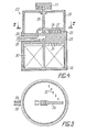
- the inductor 22 contains a cylindrical hollow housing 28 made of a dielectric material, which is provided with a removable cover 29.
- a multi-wind inductance tape reel 30 with a spiral winding which is provided with a plurality of branches 31 over the length of the winding conductor - in the embodiment to be treated here with six branches.
- Each branch 31 is connected to an associated normally closed contact 32 of a lamella selector switch 33, the common movable contact 34 of which is attached to a central axis 35 which is rotatably mounted in the housing 28.
- the selector switch 33 is protected by a cover 36 the outer surface of which is attached to a handle 37 which is fixedly connected to the end of the shaft 35 which projects beyond the cover 36 and which serves to rotate the shaft 35 together with the common contact 34 by a predetermined angle.
- the common contact 34 is connected to a power supply line 38, while one of the ends of the winding of the coil 30, in this case the inner end, is connected to a power supply line 39.
- the power supply lines 38 and 39 are fed out of the housing 28.
- Fig. 6 shows an electrical circuit for the current pulse generator 1 with the energy store 2.
- the current pulse generator 1 contains a transformer 40, a symistor 41, which is connected in series in the primary winding circuit of the transformer 40 and via the control input serving as the control input of the pulse generator 1 with the Power amplifier 14 is connected, a diode bridge 42, the inputs of which are connected to the secondary winding of the transformer 40.
- a current limiting choke 43 and an energy store 2 are connected in series, which is designed in the form of a battery of capacitors which form a discharge circuit through which a charging current flows periodically when the device is operating.
- the capacitor bank 44 can be designed on the basis of pulse capacitors with low self-inductance.
- the switching element 5 represents a symistor in the given embodiment variant.
- a Hall crystal converter serves as the magnetic field pulse generator 12.
- Emitter followers can be used as power amplifiers 8 and 14, each of which is constructed on a composite transistor.
- a pulse generator 15 z. B. uses a well known LF pulse generator. be built on microcircuits and in which the pulse frequency and duration by changing the parameters of the frequency-determining LC chain to the signals of the pulse frequency and Im Pulse duration adjuster 17 or 19 are changed as which selector switches are used.
- the pulse number adjuster 21 represents a decade selector switch, while a pulse counter and a digital comparator are also connected to the circuit of the pulse generator 15.
- the outputs of the decade selector switch are connected to a group of inputs of the digital comparator, while the outputs of the pulse counter are connected to the other group of inputs of the same digital comparator (not shown).
- the magnetic field pulse amplitude controller 10 contains a memory unit 45, one input of which is connected to the input 11 of the controller 10 and the other input of which is connected to the input 9 of the controller 10, a comparison circuit 46, the first input of which is connected to the output of the storage unit 45 and its second input via a controllable switch 47 to the output of a magnetic field pulse amplitude adjuster 43, a summator 49, the first input of which is connected to the output of the comparison circuit 46 and the second input of which is connected directly to the output of the magnetic field pulse map adjuster 48 is a comparison circuit 50, the first input of which is connected to the output of the summer 49 and the second input of which is connected via a voltage divider to the input 13 of the controller 10 and the output of which forms the output of the magnetic field pulse regulator 10, and a control circuit 52 for the switch 47, whose input is connected to the input 9 of the controller 10 and whose output is connected to the control input of the switch 47.
- the control circuit 52 of the switch 47 can be constructed on the basis of an RS flip-flop.
- the device for magnetotherapy according to the invention works as follows.
- the capacitor battery 44 (FIG. 6) of the energy store 2 begins to charge because the symmetry 41 is conductive in the initial state, so that the charging current flows through the primary winding of the transformer 40.
- An AC voltage occurs on the secondary winding of the transformer 40, which is converted into a DC voltage in the diode rectifier 42.
- the choke 43 serves to limit the charging current.
- the switching element 5 switches the discharge circuit 3 to the output of the energy store 2, so that the discharge of the store 2 takes place via the discharge circuit 3, which is provided with the control part 6 for the leading edge steepness of the magnetic field pulses, by means of the selector switch in the discharge circuit 3 27 (FIG. 3) one of the LC chains 23 to 26, e.g. B. the LC chain 23 is turned on. Switching the LC chains 23 to 26 in the control section 6 leads to a change in the equivalent sizes of the resistance R o , the inductance L, the capacitance C o of the discharge circuit 3 (FIG. 1), by means of which the parameters of the magnetic field pulses of the inductor 4, in particular, the leading edge rise time ⁇ of the magnetic field pulse can be determined, which determines the leading edge steepness of the pulse.
- In Pig. 8 are curves for a magnetic field pulse from the inductor 4 (FIG. 1) for various circuit types of the LC chains 23 to 26 (FIG. 3) in the control part 6 for the leading edge steepness.
- the curve “a” represents a pulse curve when the LC chain 23 is connected to the switching element 5 (FIG. 1) via the selector switch 27, the curve “b” when the LC chain 24 is connected, and the curve “c” when the LC chain 25 and the curve “d” at the shoulder of the ⁇ C chain 26.
- the magnetic field pulse amplitude controller 10 (Fig. 10) functions as follows.
- the storage unit 45 After switching on the device for magnetotherapy, before the first discharge pulse of the energy store is delivered and a signal is to be written into the storage unit 45, which is assigned to the actual amplitude of the magnetic field pulse and arrives from the magnetic field pulse amplitude transmitter 12 (FIG. 1), to the first input of the Comparison circuit 46 (Fig. 7) applied a zero signal.
- the zero signal is also at the second input of the circuit 46, because no signal from the magnetic field pulse amplitude adjuster 48 passes through the controllable switch 47, which is blocked by a signal arriving from the control circuit 52.
- the comparison circuit 46 supplies a zero signal which arrives at an input of the summer 49.
- a signal from the magnetic field pulse amplitude adjuster 48 arrives at the second input of the summator 49.
- the signal of the amplitude adjuster 48 which is the same as the signal, is fed to the comparison circuit 50, in which it is compared with a signal which passes through the voltage divider 51 via the input 13 from the energy store 2 (FIG. 1) and information about represents the value of the voltage applied to this memory.
- a signal arrives at the input of the amplitude controller 10 from the output of the unit 7 (FIG. 1) and is passed on to the input of the memory unit 45 (FIG. 7), which brings the latter into a state in which it is ready to Record pulses from the pulse amplitude transmitter 12 (FIG. 1) and the control circuit 52 (FIG. 7) is supplied, at the output of which a signal is formed which unlocks the switch 47 via the control input.
- the switch 47 is in the conductive state from the time of arrival of the first pulse to a time when the modules are on Direction after the generation of the number of pulses are brought into the initial state, which is preset on the pulse number adjuster 21 (FIG. 1) of the unit 7.
- the inputs of the comparison circuit 46 are supplied with a signal corresponding to the actual amplitude of the magnetic field pulse and a signal assigned to the desired value of the amplitude from the magnetic field pulse amplitude adjuster 43 via the conductive switch 47.
- the comparison circuit 46 the target and the actual amplitude of the magnetic field pulse are compared and a deviation signal is supplied. This arrives at the first input of the summator 49, where it changes the signal value from the amplitude adjuster 48 (enlarged or reduced value from the amplitude adjuster 48 (enlarged or reduced), which is fed to the second input of the summator 43, from whose output the signal is sent to the is applied to the first input of the comparison circuit 50.
- This signal is essentially the signal which specifies the amplitude of the magnetic field pulse, taking into account the correction of disturbance variables, which occurs in the discharge circuit 3 (FIG. 1), in particular when switching the LC chains 23 to 26 (FIG. 3) in the control section 6.
- This keeps the amplitude of the magnetic field pulses of the inductor 4. Constant, for example, if the actual amplitude of the magnetic field pulse is higher than the target amplitude, then a signal level is present at the input of the comparison circuit 50 that is lower than that of the pulse amplitude adjuster 43.
- the signal arriving at the second input of the comparison circuit 50 from the voltage divider 51 is equal to the signal lying at the first input at a lower voltage at the energy store 2 (FIG. 1). Since the voltage at the energy store 2 became lower, the amplitude of the magnetic field pulse when the store 2 is discharged via the discharge circuit 3 becomes ver decreases, ie it becomes the setpoint.
- the work cycle of the facility is then repeated. After the number of magnetic field pulses generated by the device for magnetotherapy has reached the desired value specified by the adjuster 21, the function of the device is interrupted and brought into the initial state.
- the parameters of the discharge circuit 3 of the energy store 2 are dimensioned such that when working at the highest frequency, the energy store 3 is charged for charging to the maximum value.
- the magnetotherapy device whose circuit diagram is shown in FIG. 2, also works in a similar manner.
- the difference is that the slope of the magnetic field pulses is regulated by changing the inductance of the inductor 22 itself.
- the control part 6 FIG. 1
- this change is detected by the magnetic field pulse amplitude transmitter 12, and the controller 10 compensates for this change, so that the amplitude of the magnetic field pulses is maintained equal to the target value H m .
- the device according to the invention for magnetotherapy provides for the generation of magnetic pulses on the working surface of the inductor, with a duration of 10 -2 to 10 -6 s, an amplitude of 500 to 2000 kA / m and a repetition frequency of 0.25 to 2 Hz exhibit.
- the advantage of the device according to the invention is the possibility of dynamic control of the therapeutic treatment process.
- a value of the specified parameter can be selected according to the individual sensitivity of the organism and an analgesic effect can be achieved in an optimally short period of time.
- the device according to the invention makes it possible to change the leading edge steepness of the pulses within the range of 5.1 05 to 2.10 8 kA / ms by increasing the front edge steepness of the impulses and the controllability of this steepness improves the therapeutic treatment effect, namely that in the treatment of lumbosacral radiculitis with a single action the pain numbing time can be shortened on average by 2.5 times and at the same time the retention time of the pain numbing effect can be reduced by an average Extend 4.5 times.
- the automatic stabilization of the magnetic field amplitude avoids manual monitoring and keeping the magnetic field amplitude constant, which simplifies the treatment process and shortens the time period for carrying out a magnetotherapy treatment step.
- a test sample of the device according to the invention for magnetotherapy was produced and tested under clinical conditions.
- the device according to the invention for magnetotherapy was used to dock acute post-traumatic pain in steps where a necrosis has been cut out in a patient with purulent and necrotic leg wounds.
- An amplitude of the pulses of the healing magnetic field of 1300 kA / m, a pulse duration of 3.10 -4 s, an initial speed of the pulse leading edge of 2.5.10 7 kA / ms were set.
- the analgesic effect was maintained for 6 hours. After five treatment steps with 100 pulses each, the wounds healed and the pain disappeared.
- the device for magnetotherapy according to the invention was used for docking phantom pain in a patient with a left stump.
- An amplitude of the magnetic field pulses of 1500 kA / m, a pulse duration of 3.10 -4 s, a rising speed of the pulse leading edge of 7.5.10 7 kA / ms were set.
- the crane kicked a state of subjective numbness.
- the pain relief effect was maintained for two hours
- the second treatment step with 70 pulses the pain numbing effect was retained for 10.5 hours and after the third treatment step with 70 pulses, there was no more phantom pain.
Abstract
Applications Claiming Priority (3)
| Application Number | Priority Date | Filing Date | Title |
|---|---|---|---|
| SU884408261A SU1766422A1 (ru) | 1988-04-25 | 1988-04-25 | Устройство дл магнитотерапии |
| SU4408261 | 1988-04-25 | ||
| PCT/SU1989/000097 WO1989010159A1 (fr) | 1988-04-25 | 1989-04-14 | Dispositif de magnetotherapie |
Publications (3)
| Publication Number | Publication Date |
|---|---|
| EP0380681A1 true EP0380681A1 (fr) | 1990-08-08 |
| EP0380681A4 EP0380681A4 (en) | 1992-07-08 |
| EP0380681B1 EP0380681B1 (fr) | 1996-08-28 |
Family
ID=21367925
Family Applications (1)
| Application Number | Title | Priority Date | Filing Date |
|---|---|---|---|
| EP89905824A Expired - Lifetime EP0380681B1 (fr) | 1988-04-25 | 1989-04-14 | Dispositif de magnetotherapie |
Country Status (15)
| Country | Link |
|---|---|
| EP (1) | EP0380681B1 (fr) |
| JP (1) | JPH03502654A (fr) |
| CN (1) | CN1015961B (fr) |
| AT (1) | ATE141811T1 (fr) |
| AU (1) | AU3565989A (fr) |
| BG (1) | BG50376A3 (fr) |
| BR (1) | BR8906928A (fr) |
| DD (1) | DD283775A5 (fr) |
| DE (1) | DE58909823D1 (fr) |
| FI (1) | FI896269A0 (fr) |
| HU (1) | HUT59842A (fr) |
| PL (1) | PL279103A1 (fr) |
| SU (1) | SU1766422A1 (fr) |
| WO (1) | WO1989010159A1 (fr) |
| YU (1) | YU85389A (fr) |
Families Citing this family (3)
| Publication number | Priority date | Publication date | Assignee | Title |
|---|---|---|---|---|
| AU645955B3 (en) * | 1993-05-26 | 1994-01-27 | Chuan-Hung Kao | Electric relaxer |
| KR100692204B1 (ko) * | 2004-11-26 | 2007-03-09 | (주) 엠큐브테크놀로지 | 완충용 인덕터 기능을 수행할 수 있는 변압기를 구비한전기 회로 및 이를 이용한 자기 자극기 |
| CN103127612A (zh) * | 2013-03-04 | 2013-06-05 | 任国祚 | 危重病人止痛仪 |
Citations (7)
| Publication number | Priority date | Publication date | Assignee | Title |
|---|---|---|---|---|
| US3841305A (en) * | 1972-10-25 | 1974-10-15 | Univ Iowa State Res Found Inc | External inductive neural stimulator system |
| EP0026481A2 (fr) * | 1979-09-27 | 1981-04-08 | Siemens Aktiengesellschaft | Stimulateur cardiaque |
| EP0048451A1 (fr) * | 1980-09-24 | 1982-03-31 | 121873 Canada Inc. | Système et procédé électro-magnétiques de thérapie |
| WO1985002547A1 (fr) * | 1983-12-08 | 1985-06-20 | Gyueling Zoltan | Procede therapeutique non-envahissant et installation electrique pour realiser ledit procede |
| US4654574A (en) * | 1983-06-29 | 1987-03-31 | Sheldon Thaler | Apparatus for reactively applying electrical energy pulses to a living body |
| EP0217011A1 (fr) * | 1985-07-06 | 1987-04-08 | Hans Rodler | Appareil d'électrothérapie universel |
| SU1309274A1 (ru) * | 1985-09-02 | 1987-05-07 | В. И. Турченков | Устройство дл формировани переднего фронта импульсов |
Family Cites Families (5)
| Publication number | Priority date | Publication date | Assignee | Title |
|---|---|---|---|---|
| SU697131A1 (ru) * | 1975-06-06 | 1979-11-15 | Предприятие П/Я А-1427 | Устройство дл воздействи магнитным полем на биологические объекты |
| SU1273122A1 (ru) * | 1983-05-23 | 1986-11-30 | Витебское отделение Института физики твердого тела и полупроводников АН БССР | Аппарат дл магнитотерапии |
| IT1159024B (it) * | 1983-06-02 | 1987-02-25 | Ruggero Cadossi | Metodo e dispositivo per il trattamento di tessuti e cellule viventi mediante campi elettromagnetici pulsanti |
| CS252197B1 (cs) * | 1985-03-04 | 1987-08-13 | Jaroslav Kansky | Zapojení impulsního magnetoterapeutického přístroje |
| GB8601138D0 (en) * | 1986-01-17 | 1986-02-19 | Lyon R J | Therapy device |
-
1988
- 1988-04-25 SU SU884408261A patent/SU1766422A1/ru active
-
1989
- 1989-04-14 AT AT89905824T patent/ATE141811T1/de not_active IP Right Cessation
- 1989-04-14 EP EP89905824A patent/EP0380681B1/fr not_active Expired - Lifetime
- 1989-04-14 WO PCT/SU1989/000097 patent/WO1989010159A1/fr active IP Right Grant
- 1989-04-14 DE DE58909823T patent/DE58909823D1/de not_active Expired - Fee Related
- 1989-04-14 AU AU35659/89A patent/AU3565989A/en not_active Abandoned
- 1989-04-14 BR BR898906928A patent/BR8906928A/pt unknown
- 1989-04-14 HU HU892984A patent/HUT59842A/hu unknown
- 1989-04-14 JP JP1505766A patent/JPH03502654A/ja active Pending
- 1989-04-24 YU YU00853/89A patent/YU85389A/xx unknown
- 1989-04-24 DD DD89327922A patent/DD283775A5/de not_active IP Right Cessation
- 1989-04-24 BG BG88207A patent/BG50376A3/xx unknown
- 1989-04-25 PL PL27910389A patent/PL279103A1/xx unknown
- 1989-04-25 CN CN89103681.4A patent/CN1015961B/zh not_active Expired
- 1989-12-22 FI FI896269A patent/FI896269A0/fi not_active IP Right Cessation
Patent Citations (7)
| Publication number | Priority date | Publication date | Assignee | Title |
|---|---|---|---|---|
| US3841305A (en) * | 1972-10-25 | 1974-10-15 | Univ Iowa State Res Found Inc | External inductive neural stimulator system |
| EP0026481A2 (fr) * | 1979-09-27 | 1981-04-08 | Siemens Aktiengesellschaft | Stimulateur cardiaque |
| EP0048451A1 (fr) * | 1980-09-24 | 1982-03-31 | 121873 Canada Inc. | Système et procédé électro-magnétiques de thérapie |
| US4654574A (en) * | 1983-06-29 | 1987-03-31 | Sheldon Thaler | Apparatus for reactively applying electrical energy pulses to a living body |
| WO1985002547A1 (fr) * | 1983-12-08 | 1985-06-20 | Gyueling Zoltan | Procede therapeutique non-envahissant et installation electrique pour realiser ledit procede |
| EP0217011A1 (fr) * | 1985-07-06 | 1987-04-08 | Hans Rodler | Appareil d'électrothérapie universel |
| SU1309274A1 (ru) * | 1985-09-02 | 1987-05-07 | В. И. Турченков | Устройство дл формировани переднего фронта импульсов |
Non-Patent Citations (2)
| Title |
|---|
| See also references of WO8910159A1 * |
| Soviet Inventions Illustrated Sektion EL DERWENT publ. LONDON (GB), Woche 8750, Seite 8, & SU-A-1 309 274 (V.I. TURCHENKOV) 07.05.87 * |
Also Published As
| Publication number | Publication date |
|---|---|
| BG50376A3 (en) | 1992-07-15 |
| EP0380681A4 (en) | 1992-07-08 |
| SU1766422A1 (ru) | 1992-10-07 |
| AU3565989A (en) | 1989-11-24 |
| HU892984D0 (en) | 1990-07-28 |
| JPH03502654A (ja) | 1991-06-20 |
| BR8906928A (pt) | 1990-11-20 |
| YU85389A (en) | 1991-10-31 |
| ATE141811T1 (de) | 1996-09-15 |
| WO1989010159A1 (fr) | 1989-11-02 |
| DD283775A5 (de) | 1990-10-24 |
| HUT59842A (en) | 1992-07-28 |
| FI896269A0 (fi) | 1989-12-22 |
| CN1037279A (zh) | 1989-11-22 |
| CN1015961B (zh) | 1992-03-25 |
| PL279103A1 (en) | 1990-01-08 |
| EP0380681B1 (fr) | 1996-08-28 |
| DE58909823D1 (en) | 1997-11-27 |
Similar Documents
| Publication | Publication Date | Title |
|---|---|---|
| DE102013211859B4 (de) | Magnetstimulator zur Stimulation eines Gewebes durch ein Magnetfeld | |
| DE3315513A1 (de) | Digitale schaltungsanordnung zum steuern eines allmaehlichen einschaltens von elektrischen gewebereizeinrichtungen | |
| DE102009023855B4 (de) | Vorrichtung zur Nervenreizung mit Magnetfeldimpulsen | |
| DE102006024467B4 (de) | Magnetischer Neurostimulator | |
| DE102017108084B4 (de) | Pulsquelle und Verfahren für die magnetisch induktive Nervenreizung | |
| EP0526493B1 (fr) | Procede de commande d'un stimulateur de tissus | |
| EP0425673A1 (fr) | Procede et dispositif produisant des impulsions electriques destinees a stimuler des objets biologiques | |
| DE19607704A1 (de) | Vorrichtung zur magnetischen Anregung von neuro-muskularem Gewebe | |
| DE10237519A1 (de) | Magnetfeldtherapie | |
| EP0211822A2 (fr) | Appareil électromédical pour thérapie | |
| EP0811398A2 (fr) | Stimulateur implantable | |
| EP0574609B1 (fr) | Defibrillateur/cardioverteur | |
| WO2008089726A1 (fr) | Implant pour stimuler des cellules nerveuses | |
| EP0380681B1 (fr) | Dispositif de magnetotherapie | |
| DE2929293C2 (de) | Vorrichtung zur Elektrostimulation | |
| EP0196393B1 (fr) | Appareil de stimulation électrique, en particulier pour traitement de la scoliose | |
| EP0165285B1 (fr) | Circuit électique pour une appareil médical produisant un champ magnétique variable | |
| EP2676624B1 (fr) | Appareil chirurgical haute fréquence | |
| EP0569616B1 (fr) | Implant pour la délivrance de impulsions électriques à un tissu vivant | |
| DE10065104B4 (de) | Defibrillator | |
| DE3405630C1 (de) | Gerät zur Schmerzbehandlung durch elektrische Stimulation | |
| DE19801351B4 (de) | Niedrigfrequenztherapievorrichtung | |
| EP0029479A1 (fr) | Dispositif pour la stimulation électrique du coeur | |
| DE602004009262T2 (de) | Elektrotherapievorrichtung | |
| DE102015212546A1 (de) | Hochfrequenzgenerator zum Anschluss elektrochirurgischer Instrumente |
Legal Events
| Date | Code | Title | Description |
|---|---|---|---|
| PUAI | Public reference made under article 153(3) epc to a published international application that has entered the european phase |
Free format text: ORIGINAL CODE: 0009012 |
|
| 17P | Request for examination filed |
Effective date: 19891222 |
|
| AK | Designated contracting states |
Kind code of ref document: A1 Designated state(s): AT CH DE FR GB IT LI NL SE |
|
| A4 | Supplementary search report drawn up and despatched |
Effective date: 19920514 |
|
| AK | Designated contracting states |
Kind code of ref document: A4 Designated state(s): AT CH DE FR GB IT LI NL SE |
|
| 18D | Application deemed to be withdrawn |
Effective date: 19931103 |
|
| D18D | Application deemed to be withdrawn (deleted) | ||
| 17Q | First examination report despatched |
Effective date: 19950302 |
|
| GRAH | Despatch of communication of intention to grant a patent |
Free format text: ORIGINAL CODE: EPIDOS IGRA |
|
| GRAA | (expected) grant |
Free format text: ORIGINAL CODE: 0009210 |
|
| AK | Designated contracting states |
Kind code of ref document: B1 Designated state(s): AT CH DE FR GB IT LI NL SE |
|
| PG25 | Lapsed in a contracting state [announced via postgrant information from national office to epo] |
Ref country code: IT Free format text: LAPSE BECAUSE OF FAILURE TO SUBMIT A TRANSLATION OF THE DESCRIPTION OR TO PAY THE FEE WITHIN THE PRE;WARNING: LAPSES OF ITALIAN PATENTS WITH EFFECTIVE DATE BEFORE 2007 MAY HAVE OCCURRED AT ANY TIME BEFORE 2007. THE CORRECT EFFECTIVE DATE MAY BE DIFFERENT FROM THE ONE RECORDED.SCRIBED TIME-LIMIT Effective date: 19960828 Ref country code: FR Effective date: 19960828 Ref country code: NL Free format text: LAPSE BECAUSE OF FAILURE TO SUBMIT A TRANSLATION OF THE DESCRIPTION OR TO PAY THE FEE WITHIN THE PRESCRIBED TIME-LIMIT Effective date: 19960828 |
|
| REF | Corresponds to: |
Ref document number: 141811 Country of ref document: AT Date of ref document: 19960915 Kind code of ref document: T |
|
| PG25 | Lapsed in a contracting state [announced via postgrant information from national office to epo] |
Ref country code: SE Effective date: 19961128 |
|
| GBT | Gb: translation of ep patent filed (gb section 77(6)(a)/1977) |
Effective date: 19961224 |
|
| EN | Fr: translation not filed | ||
| NLV1 | Nl: lapsed or annulled due to failure to fulfill the requirements of art. 29p and 29m of the patents act | ||
| PG25 | Lapsed in a contracting state [announced via postgrant information from national office to epo] |
Ref country code: CH Free format text: LAPSE BECAUSE OF NON-PAYMENT OF DUE FEES Effective date: 19970430 Ref country code: LI Free format text: LAPSE BECAUSE OF NON-PAYMENT OF DUE FEES Effective date: 19970430 |
|
| PGFP | Annual fee paid to national office [announced via postgrant information from national office to epo] |
Ref country code: AT Payment date: 19970515 Year of fee payment: 9 |
|
| PGFP | Annual fee paid to national office [announced via postgrant information from national office to epo] |
Ref country code: SE Payment date: 19970516 Year of fee payment: 9 |
|
| PLBE | No opposition filed within time limit |
Free format text: ORIGINAL CODE: 0009261 |
|
| STAA | Information on the status of an ep patent application or granted ep patent |
Free format text: STATUS: NO OPPOSITION FILED WITHIN TIME LIMIT |
|
| 26N | No opposition filed | ||
| REF | Corresponds to: |
Ref document number: 58909823 Country of ref document: DE Date of ref document: 19971127 |
|
| REG | Reference to a national code |
Ref country code: GB Ref legal event code: 732E |
|
| PG25 | Lapsed in a contracting state [announced via postgrant information from national office to epo] |
Ref country code: AT Free format text: LAPSE BECAUSE OF NON-PAYMENT OF DUE FEES Effective date: 19980414 |
|
| PGFP | Annual fee paid to national office [announced via postgrant information from national office to epo] |
Ref country code: GB Payment date: 19980414 Year of fee payment: 10 |
|
| PGFP | Annual fee paid to national office [announced via postgrant information from national office to epo] |
Ref country code: DE Payment date: 19980630 Year of fee payment: 10 |
|
| PG25 | Lapsed in a contracting state [announced via postgrant information from national office to epo] |
Ref country code: GB Free format text: LAPSE BECAUSE OF NON-PAYMENT OF DUE FEES Effective date: 19990414 |
|
| GBPC | Gb: european patent ceased through non-payment of renewal fee |
Effective date: 19990414 |
|
| PG25 | Lapsed in a contracting state [announced via postgrant information from national office to epo] |
Ref country code: DE Free format text: LAPSE BECAUSE OF NON-PAYMENT OF DUE FEES Effective date: 20000201 |