EP0380681A1 - Magnetotherapy device - Google Patents
Magnetotherapy device Download PDFInfo
- Publication number
- EP0380681A1 EP0380681A1 EP89905824A EP89905824A EP0380681A1 EP 0380681 A1 EP0380681 A1 EP 0380681A1 EP 89905824 A EP89905824 A EP 89905824A EP 89905824 A EP89905824 A EP 89905824A EP 0380681 A1 EP0380681 A1 EP 0380681A1
- Authority
- EP
- European Patent Office
- Prior art keywords
- magnetic field
- output
- input
- inductor
- pulse
- Prior art date
- Legal status (The legal status is an assumption and is not a legal conclusion. Google has not performed a legal analysis and makes no representation as to the accuracy of the status listed.)
- Granted
Links
Images


Classifications
-
- A—HUMAN NECESSITIES
- A61—MEDICAL OR VETERINARY SCIENCE; HYGIENE
- A61N—ELECTROTHERAPY; MAGNETOTHERAPY; RADIATION THERAPY; ULTRASOUND THERAPY
- A61N2/00—Magnetotherapy
- A61N2/02—Magnetotherapy using magnetic fields produced by coils, including single turn loops or electromagnets
Abstract
Description
Die vorliegende Erfindung betrifft die Medizin und bezieht sieb insbesondere auf eine Einrichtung zur Magneto - therapie.The present invention relates to medicine and relates in particular to a device for magnetotherapy.
Es ist eine Einribhtung zur Magnetotherapie bekannt, die -- in Reihe geschaltet -- einen Stromimpulsgenerator, einen Energiespeicher und einen Entladungskreis für den letzteren enthält, wobei der Entladungskreis ein steuerbares Schaltelement und einen Induktor aufweist, durch den ein heilendes Implusmagnetfeld erzeugbar ist. Darüber hinaus enthält die Einrichtung eine Einheit zur Steuerung der Magnetfeldimpulsdauer des Induktors, deren Ausgang an den Steuereingang des Schaltelementes angeschlossen ist (SU, A, 1321426).A device for magnetotherapy is known which, when connected in series, contains a current pulse generator, an energy store and a discharge circuit for the latter, the discharge circuit having a controllable switching element and an inductor by means of which a healing implus magnetic field can be generated. In addition, the device contains a unit for controlling the magnetic field pulse duration of the inductor, the output of which is connected to the control input of the switching element (SU, A, 1321426).
Die bekannte Einrichtung ist für die Betäubung bei Radikulitis, Plexitis und anderen Erkrankungen sowie für die Steuerung der Verschiebung von Röntgen-Kontrastmitteln im Organismus des Patienten bestimmt. Beim Einsatz der bekannten Einrichtung wählt der Arzt die für den Patienten geeignetste Amplitude und Dauer der Impulse eines heildenden Magnetfeldes des Induktors und eine Anzahl von Bebandlungsschritten, während der auf den Kranken mit dem Magnetfeld eingewirkt wird. Dabei beträgt die für die Auswahl der optimalen Parameter magnetiescher Impulse benötigte Zeit in der Regel mindestens 3 bis 7 Minuten. Während der Durchführung einer Behandlung der Magnetotherapie sind infolge Schwankungen der Charakteristiken der Baueinheiten der Einrichtung, hervorgerufen z. B. durch deren Erwärmung, Amplitudensprünge und Magnetfeldimpulse möglich, darunter auch auf Werte, die den zulässigen Wert übersteigen.The known device is intended for anesthesia in the case of radiculitis, plexitis and other diseases and for controlling the displacement of X-ray contrast media in the patient's organism. When using the known device, the doctor selects the most suitable amplitude and duration of the impulses of a healing magnetic field of the inductor and a number of treatment steps during which the patient is acted on with the magnetic field. The time required to select the optimal parameters of magnetic pulses is usually at least 3 to 7 minutes. During the implementation of a magnetotherapy treatment, fluctuations in the characteristics of the structural units of the device, e.g. B. possible by their heating, amplitude jumps and magnetic field pulses, including values that exceed the permissible value.
Bekannt ist ferner eine Einrichtung zur Magnetotherapie, die -- in Reihe geschaltet -- einen steuerbaren Stromimpulsgenerator, einen Energiespeicher und einen Entladungskreis für den letzteren enthält, welcher ein steuerbares Schaltelement und einen Induktor aufweist, durch den ein heilendes Impulsmagnetfeld erzeugbar ist, und die mit einer Einheit zur Steuerung der Magnetfeldimpulsdsuer des Induktors, deren Ausgang an den Steuereingang des Schaltelementes angeschlossen ist, und einem Magnetfeldimpulsamplitudenregler versehen ist, dessen Ausgang an den Steuereingang des Impulsgeneraturs angeschlossen ist (EP, B, 0043451). Der Amplitudenregler dieser Einrichtung gewährleistet eine Begrenzung der Spitzenwerte der Amplitude der Magnetfeldimpluse. Die Auswahl der für den Patienten optimalen Parameter der Impulse eines heilenden Magnetfeldes wird jedoch bei Verwendung der letztgenannten Einrichtung durch längeres Variieren der Werte der lmpulsamplitude und -dauer durchgeführt, was eine beträchtliche Zeit in Anspruch nimmt und sich nicht in allen Fällen als effektiv erweist. Insbesondere erweist sich als kompliziert die Auswahl der optimalen Parameter mit Hilfe der bekannten Einrichtung beim Kupieren eines akuten schmerzhaften Syndroms, von Phantomschmerzen, BronchialasthmaanfällenAlso known is a device for magnetotherapy, which - connected in series - contains a controllable current pulse generator, an energy store and a discharge circuit for the latter, which has a controllable switching element and an inductor, by means of which a healing pulse magnetic field can be generated, and which one Unit for controlling the magnetic field pulse inductor, the output of which is connected to the control input of the switching element, and a magnetic field pulse amplitude controller, the output of which is connected to the control input of the pulse generator (EP, B, 0043451). The amplitude controller of this device ensures that the peak values of the amplitude of the magnetic field impluse are limited. However, the selection of the parameters of the pulses of a healing magnetic field that are optimal for the patient is carried out by using the latter device by varying the values of the pulse amplitude and duration for a longer time, which takes a considerable time and does not prove to be effective in all cases. In particular, the selection of the optimal parameters with the aid of the known device for the docking of an acute painful syndrome, phantom pain, bronchial asthma attacks proves to be complicated
Der Erfindung liegt die Aufgabe zugrunde, die Einrichtung zur Magnetotherapie so zu vervollkommnen, daß sie über Mittel zur Auswahl der Parameter und Form der Impulse eines heilenden Magnetfeldes verfügt, welche das Kupieren eines akuten schmerzhaften Syndroms, von Phantomschmerzen, Bronchialasthmaanfällen für einen konkreten Kranken in möglichst kurzen Zeiträumen sichern.The invention has for its object to perfect the device for magnetotherapy so that it has means for selecting the parameters and shape of the impulses of a healing magnetic field, which the cropping of an acute painful syndrome, phantom pain, bronchial asthma attacks for a specific patient in as possible secure short periods.
Das Wesen der Erfindung besteht darin, daß bei der Einrichtung zur Magnetotherapie, die -- in Reihe geschaltet -- einen steuerbaren Stromimpulsgenerator, einen Energiespeicher und einen Entladungskreis für denselben enthält, welcher ein steuerbares Schaltelement und einen Induktor, durch den ein heilendes Impulsmagnetfeld erzeugbar ist, aufwreist, und die mit einer Einheit zur Steuerung der Magnetfeldimpulsdauer des Induktors, deren dusgang an den Steuereingang des Schaltelementes angeschlossen ist, und einem Magnetfeldimpluslamplitudenregler versehen ist, dessen Ausgang an den Steuereingang des Impulsgenerators angeschlossen ist, gemä3 der Erfindung in den Entladungskreis des Energiespeichers ein Regelteil für die Vorderflankensteilheit der Magnetfeldimpulse des Induktors geschaltet ist.The essence of the invention is that in the device for magnetotherapy, which - connected in series - contains a controllable current pulse generator, an energy store and a discharge circuit for the same, which has a controllable switching element and an inductor through which a healing pulse magnetic field can be generated , and which is provided with a unit for controlling the magnetic field pulse duration of the inductor, the output of which is connected to the control input of the switching element, and a magnetic field amplitude controller, the output of which is connected to the control input of the pulse generator, according to the invention into the discharge circuit of the energy store Control section is switched for the leading edge steepness of the magnetic field pulses of the inductor.
Der Regelteil für die Vorderflsnkensteilheit der Magnetfeldimpulse des Induktors kann zwischen dem Ausgang des Energiespeichers und dem Eingang des Schaltelementes geschaltet sein und mindestens zwei LC-Ketten enthalten, deren eine Anschlußenden zusammegescraltet sind, und einen Wahlschalter aufweisen, dessen Ruhekontakte mit den anderen Anschlußenden der entsprechenden LC-Ketten verbunden sind.The control part for the steepness of the front surface of the magnetic field pulses of the inductor can be connected between the output of the energy store and the input of the switching element and can contain at least two LC chains, one of the connection ends of which are interconnected, and a selector switch whose normally closed contacts with the other connection ends of the corresponding LC Chains are connected.
Man kann, wenn der Induktor eine mehrwindige Induktivitätsspule darstellt, mit dieser den Regelteil für die Vorderflankensteilheit der Magnetfeldimpulse konstruktiv vereinigen, wozu die Wicklung der Induktivitätsspule mit einer Vielzahl von Abzweigen über die Länge des Wicklungsleiters zu versehen und die Spule an den Ausgang des Schaltelementes über einen Wanlschalter anzuschließen ist, dessen jeder Ruhekontakt mit dem zugehörigen A bzweig verbunder ist.If the inductor is a multi-wind inductance coil, the control section for the leading edge steepness of the magnetic field pulses can be constructively combined with it, for which purpose the winding of the inductance coil must be provided with a large number of branches along the length of the winding conductor and the coil to the output of the switching element via one A wall switch is to be connected, of which each normally closed contact is connected to the associated A branch.
Um die Konstanz der Inpulsamplitude bei Änderung der Impulsvorderflanke zu sichern, erweist es sich als zweckmäßig bei der Einrichtung zur Magnetotherspie, in der der Magnetfeldimpulsarnplitudenregler eine Vergleichsschaltung enthält, deren erster Eingang an den Ausgang eines Magnetfeldimpulsamplitudengebera, zweiter Eingang an den Ausgang eines Magnetfeldimpulsamplitudeneinstellers und deren Ausgang an den Ausgang des Magnetfeldimpulsamplitudenreglers angeschlossen sind, in den Amplitudenregler eine zwischen dem Ausgang des Magnetfeldimpulsamplitudengebers und dem ersten Eingang der Vergleicbsscbaltung geschaltete Speichereinheit und eine zweite Vergleichsschaltung zusätzlich einzuiführen, deren erster Eingang mit dem Ausgang der ersten Vergleichsschaltung, zweiter Eingang über einen Spannungsteiler mit dem Ausgang des Energiespeichers und deren Ausgang mit dem Ausgang des Amplitudenreglers verbunden sind.In order to ensure the constancy of the pulse amplitude when the pulse leading edge changes, it proves to be expedient for the device for magnetotherspy, in which the magnetic field pulse amplitude controller contains a comparison circuit, the first input of which is at the output of a magnetic field pulse amplitude generator, the second input is at the output of a magnetic field pulse amplitude adjuster and its output are connected to the output of the magnetic field pulse amplitude controller, additionally introduce a memory unit connected between the output of the magnetic field pulse amplitude transmitter and the first input of the comparative circuit and a second comparison circuit, the first input of which is connected to the output of the first comparison circuit, the second input is connected to the output via a voltage divider of the energy store and their output are connected to the output of the amplitude controller.
Die erfindungsgemäß ausgeführte Einrichtung zur Magne to therapie bietet durch Auswahl eines optimalen Wertes der Vorderflankenanstiegszeit des Impulses eines heilenden Magnetfeldes die Möglichkeit, einen akuten schmerzhaften Syndrom, Fhantonschmerzen, einen Bronchislasthmsanfall während erster drei Minuten vom Anfang der Einwirkung an zu kupieren. Die Verwendung der erfindungsgemäßen Einrichtung garantiert die Beibehaltung des Schmerzbetäubungseffektes im Laufe von 6 bis 12 Stunden nach dem Aufhören der magnetotherapeutischen Heilung.The inventive device for By selecting an optimal value of the leading edge rise time of the impulse of a healing magnetic field, Magne to therapie offers the possibility of docking an acute painful syndrome, Fhanton pain, an attack of bronchial stress during the first three minutes from the beginning of the action. The use of the device according to the invention guarantees the maintenance of the pain-numbing effect within 6 to 12 hours after the cessation of magnetotherapy.
Nachstehend wird die Erfindung anhand von konkreten Ausführungsformen unter Bezugnahme auf die beigelegten Zeichnungen näher erläutert. Es zeigt:
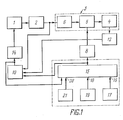
- Fig. 1 ein Strulcturschaltbild einer erfindungsgemäßen Einrichtung zur Magnetotherapie;
- Fig. 2 ein Strukturschaltbild einer Ausfuhrungsform der Einrichtung zur Magnetotherapie, bei der der Induktor und der Regelteil für die Vorderflankensteilbeit der Magnetfeidimpulse konstruktiv miteinander vereinigt sind;
- Fig. 3 eine elektrische Prinzipschaltung des Regelteils für die Vorderflankensteilheit der Magnetfeldimpulse;
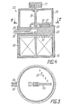
- Fig. 4 die Gesamtansicht des Induktors (im Längsschnitt), der mit dem Regelteil für die Vcrderflankensteilheit der Magnetfeldimpulse vereinigt ist;
- Fig. 5 einen Schnitt entlang der Linie V-V in Fig. 4;
- Fig. 6 eine elektrische Prinzipschaltung für den Stromimpulsgenerator und den Energiespeicher;
- Fig.7 ein Strukturschaltbild eines Amplitudenreglers;
- Fig. 8 eine Abhängigkeit der magnetischen Feldstärke H des Induktors von der Zeit (t), wobei auf der Ordinatenachse magnetische Feldstärken H in [kA/m] und auf der Abszissenachse Werte der Zeit t in [s] aufgetragen sind.
- 1 shows a structural circuit diagram of a device for magnetotherapy according to the invention;
- 2 shows a structural circuit diagram of an embodiment of the device for magnetotherapy, in which the inductor and the control part for the front flank part of the magnetic field pulses are structurally combined with one another;
- 3 shows an electrical basic circuit of the control part for the leading edge steepness of the magnetic field pulses;
- 4 shows the overall view of the inductor (in longitudinal section), which is combined with the control part for the front edge steepness of the magnetic field pulses;
- 5 shows a section along the line VV in Fig. 4.
- 6 shows a basic electrical circuit for the current pulse generator and the energy store;
- 7 shows a structural circuit diagram of an amplitude controller;
- 8 shows a dependence of the magnetic field strength H of the inductor on the time (t), magnetic field strengths H in [kA / m] being plotted on the ordinate axis and values of time t in [s] on the abscissa axis.
Die in Fig. 1 gezeigte Einrichtung zur Magnetotherapie enthält -- in Reihe geschaltet -- einen steuerbaren Stromimpulsgenerator 1, einen Energiespeicher 2 und einen Entladungskreis 3 für den Speicher 2. Der Entladungskreis 3 weist einen Induktor 4 und einen an den Eingang des letzteren über ein steuerbares Schaltelement 5 angeschlossenen Regelteil 6 für die Vorderflankensteilheit der Magnetfeldimpulse des Induktors auf, dessen Eingang seinerseits am Ausgang des Energiespeichers 2 liegt. Die Einrichtung zur Magnetotherapie ist auch mit einer Einheit Z zur Steuerung der Magnetfeldimpulsdauer versehen, deren Ausgang über einen Leistungsverstärker 8 an den Steuereingang des Schaltelementes 5 und an den Eingang 9 eines Magnetfeldimpulsamplitudenreglers 10 gelegt ist, dessen Eingang 11 am Ausgang eines Magnetfeldimpulsamplitudengebers 12 liegt und dessen Eingang 13 mit dem Ausgang des EnergieSpeichers 2 verbunden ist, wobei der Ausgang des Reglers 10 über einen Leistungsverstärker 14 an den Steuereingang des Stromimpulsgenerators 1 angeschlossen ist. Die Einheit 7 zur Steuerung der Magnetfeldimpulsdauer enthält einen Impulsgenerator 15 mit umstimmbarer Impulsfrequenz und -dauer, bei dem an den Eingang 16 ein Impulsfrequenzeinsteller 17, an den Eingang 18 ein Impulsdauereinateller 19, an den Eingang 20 ein Impulszahleinsteller 21 und an den Steuereingang der Ausgang des Magnetfeldimpulsamplitudenreglers 10 angeschlossen sind.The device for magnetotherapy shown in FIG. 1 contains - connected in series - a controllable
In Fig. 2 ist ein Strukturschaltbild einer Ausführungsvariante der Einrichtung zur Magnetotherapie gezeigt, welches sich von dem in Fig. 1 dargestellten dadurch unterscheidet, daß deren Induktor 22 mit dem Regelteil für die Vorderflankensteilheit-der Magnetfeldimpulse vereinigt ist. Hierbei entfällt im Entladungskreis 3 ein separater Regelteil für die Vorderflankensteilheit, und der Entladungskreis 3 enthält einen Induktor 22, dessen .'Eingang über das steuerbare Schaltelement 5 unmittelbar an den Ausgang des Energiespeichers 2 geschaltet ist.FIG. 2 shows a structural circuit diagram of an embodiment variant of the device for magnetotherapy, which differs from that shown in FIG. 1 in that its
Ist die Einrichtung zur Magnetotherapie nach dem in Fig. 1 gezeigten Schaltbild ausgeführt, so kann der Regelteil 6 für die Vorderflankensteilheit der Magnetfeldimpulse eine elektrische Schaltung haben, die in Fig. 3 dargestellt ist. Bei der vorliegenden Ausführungsvariante besteht er aus vier LC-Parallelkreise 23, 24, 25, 26, die iim allgemeinen Fall verschiedene L- bzw. C-Werte haben, wobei deren Eingänge zusammengeschaltet und an den Ausgang des Energiespeichers 2 angeschlossen sind und deren Ausgänge mit den Ruhekontakten eines Wahlschalters 27 in Verbindung stehen, dessen gemeinsamer beweglicher Kontakt mit dem Eingang des steuerbaren Schaltelementes 5 verbunden ist.If the device for magnetotherapy is designed according to the circuit diagram shown in FIG. 1, the
In Fig. 3 ist eine Variante des Regelteils 6 für die Vorderflankensteilheit der Magnetfeldimpulse gezeigt, bei der LC-Parallelkreise verwendet werden. Mit dewselben Erfolg kann jedoch der Regelteil 6 unter Verwendung von LC-Reihenketten oder unter gleichzeitiger Verwendung von LC-Reihen- und LC-Parallelketten ausgeführt werden, wobei er nur die Möglichkeit geben müβte, die Ersatzinduktivität L und die Ersatzkapazität C des Regelteils 6 in den geforderten Grenzen zu verändern.FIG. 3 shows a variant of the
Als Induktor 4 kann eine mehrwindige Induktivitätsspule benutzt sein, die imstande ist, auf der Arbeitsfläche des Induktors ein zureichend homogenes Impulsmagnetfeld mit einer Feldstärke von 2000 kA/m zu erzeugen.A multi-wind inductance coil can be used as the
In Fig. 4, 5 ist eine Ausführungsvariante des Induktors 22 wiedergegeben, bei der der eigentliche Induktor 22 und der Regelteil für die Vorderflankensteilheit der Magnetfeldimpulse konstruktiv vereinigt sind.4, 5, a variant of the
Der Induktor 22 enthält ein zylindrisches Hohlgehäuse 28 aus einem dielektrischen Material, welches mit einem abnehmbaren Deckel 29 versehen ist. Im Hohlraum des Gehäuses 28 ist gleichachsig mit diesem eine mehrwindige Induktivitätsbandspule 30 mit einer spiralen Wicklung untergebracht, die mit einer Vielzahl von Abzweigen 31 über die Länge des Wicklungsleiters - im hier zu behandelnden Ausführungsform mit sechs Abzweigen - versehen ist. Jeder Abzweig 31 ist mit einem zugehörigen Ruhekontakt 32 eines Lamellen-Wahlschalters 33 verbunden, dessen gemeinsamer beweglicher Kontakt 34 an einer Zentralachse 35 befestigt ist, die im Gehäuse 28 drehbar gelagert ist. Der Wahlschalter 33 ist durch einen Deckel 36 geschützt, an dessen Außenfläche ein Handgriff 37 angebracht ist, der mit dem über den Deckel 36 hinausragenden Ende der Achse 35 fest verbunden ist und zur Drehung der Achse 35 zusammen mit dem gemeinsamen Kontakt 34 um einen vorgegebenen Winkel dient. Der gemeinsame Kontakt 34 ist mit einer - Stromzuleitung 38 verbunden, während eines der Enden der Wicklung der Spule 30, im vorliegenden Fall das innere Ende, mit einer Stromzuleitung 39 verbunden sind. Die Stromzuleitungen 38 und 39 sind aus dem Gehäuse 28 herausbefübrt.The
Fig. 6 zeigt eine elektrische Schaltung für den Stromimpulsgenerator 1 mit dem Energiespeicher 2. Der Stromimpulsgenerator 1 enthält einen Transformator 40, einen Symistor 41, der in den Primärwicklungskreis des Transformators 40 in Reihe geschaltet und über den als Steuereingang des Impulsgenerators 1 dienenden Steuereingang mit dem Leistungsverstärker 14 verbunden ist, eine Diodengleichricnterbrücke 42, deren Eingänge an die Sekundärwicklung des Transformators 40 angeschlossen sind. An den Ausgang der Diodengleichrichterbrücke 42 ist eine Strombergrenzungsdrossel 43 und ein Energiespeicher 2 hintereinandergeschaltet, der in Form einer Batterie von Kondensatoren ausgeführt ist, die einen Entladungskreis bilden, durch den beim Betrieb der Einrichtung ein Ladestrom periodisch fließt. Die Kondensatorbatterie 44 kann auf Grundlage von Impulskondensatoren mit geringer Eigeninduktivität ausgeführt sein. Das Schaltelement 5 stellt in der gegebenen Ausführungsvariante einen Symistor dar.Fig. 6 shows an electrical circuit for the
Als Magnetfeldimpulsgeber 12 dient ein Hall-Kristallwandler.A Hall crystal converter serves as the magnetic
Als Leistungsverstärker 8 und 14 können Emitterfolger benutzt werden, die jeweils auf einem zusammengesetzten Transistor aufgebaut sind.Emitter followers can be used as
Als Impulsgenerator 15 kann z. B. ein weit bekannter NF-Impulsgenerator benutzt . sein, der auf Mikroschaltkreisen aufgebaut ist und bei dem die Impulsfrequenz und -dauer durch Änderung der Parameter der frequenzbestimmenden LC-Kette auf die Signale des Impulsfrequenz- und des Impulsdauereinstellers 17 bzw. 19 geändert werden, als welche Wahlschalter verwendet werden.As a pulse generator 15 z. B. uses a well known LF pulse generator. be built on microcircuits and in which the pulse frequency and duration by changing the parameters of the frequency-determining LC chain to the signals of the pulse frequency and Im
Der Impulszahleinsteller 21 stellt einen Dekaden-Wahlschalter dar, während in die Schaltung des Impulsgenerators 15 außerdem ein Impulszähler und ein Digitalkomparator geschaltet sind. Dabei sind die Ausgänge des Dekaden-Wahlschalters mit einer Gruppe von Eingägen des Digitalkomparators verbunden, während die Ausgänge des Impulszählers mit der anderen Gruppe von Eingängen des gleichen Digitalkomparators (nicht gezeigt) in Verbindung stehen.The
Der Magnetfeldimpulsamplit denregler 10, dessen Strulturschaltbild in Fig. 7 dargestellt ist, enthält eine Speichereinheit 45, deren einer Eingang an den Eingang 11 des Reglers 10 und deren anderer Eingang an den Eingang 9 des Reglers 10 angeschlossen ist, eine Vergleichsschaltung 46, deren erster Eingang mit dem Ausgang der Speichereinheit 45 und deren zweiter Eingang über einen steuerbaren Schalter 47 mit dem Ausgang eines Magnetfeldimpulsamplitudeneinstellers 43 in Verbindung steht, einen Summator 49, dessen erster Eingang an den Ausgang der Vergleichschaltung 46 gelegt ist und dessen zweiter Eingang am Ausgang des Magnetfeldimpulsmaplitudeneinstellers 48 unmittelbar liegt, eine Vergleichsschaltung 50, deren erster Eingang an den Ausgang des Summators 49 und deren zweiter Eingang über einen Spannungsteiler an den Eingang 13 des Reglers 10 angeschlossen ist und deren Ausgang den Ausgang des Magnetfeldimpulsaplitudenreglers 10 bildet, sowie eine Steuerschaltung 52 für den Schalter 47, deren Eingang an den Eingang 9 des Reglers 10 und deren Ausgang an den Steuereingang des Schalters 47 gelegt ist. Die Bauteile 45, 46, 49, 50 sind auf der Basis von Operationsverstärkern aufgebaut. Der Amplitudeneinsteller 48 stellt einen Spannungsteiler dar, der unter Verwendung eines Stellwiderstandes ausgeführt ist.The magnetic field
Die Steuerschaltung 52 des Schalters 47 kann auf der Basis eines RS-Flipflops aufgebaut werden.The
Die erfindungsgemäße Einrichtung zur Magnetotherapie arbeitet wie folgt.The device for magnetotherapy according to the invention works as follows.
Bevor man die Einrichtung ans Versorgungsnetz anschließt, stellt man - beruhend auf ärztlicher Erfahrung - mit Hilfe des Impulsfrequenz-, Impulsdauer- und Impulszahleinstellers 17 (Fig. 1), 19 bzw. 31 sowie des Magnetfeldimpulsamplitudeneinstellers 43 (Fig. 7) des Amplitudenreglers 10 und des Wahlschalters 27 (Fig 3) die für die meisten Kranken mit irgendeiner Pathologie effektivste Betriebsart der Einrichtung zur Magnetotherapie ein, d. h. es werden Frequenz, Dauer, Amplitude, Vorderflankensteilheit der Impulse des Magnetfeldes und deren Zahl für eine Heilseance vorgegeben. Der Induktor 4 (Fig. 1) wird zusammen mit dem Magnetfeldimpulsamplitudengeber 12, der in die dem zu beeinflussenden Objekt zugewandte untere Grundfläche des zylindrischen Induktors eingebaut ist, auf ein Gebiet vermutlicher therapeutischer Einwirkung so gestellt, daß die Arbeitsfläche des Induktors 4 (Stirnseite der Inuktivitätsspule) mit dem Körper des Patienten in Berührung kommt oder sich in unmittelbarer Nähe desselben befindet. Bei Zuführung der Spannung des Versorgungsnetzes an den Eingang der Einrichtung zur Magnetotherapie beginnt die Kondenaatorenbatterie 44 (Fig.6) des Energiespeichers 2 sich aufzuladen, weil der Symistor 41 im Ausgangszustand leitend ist, so daß der Ladestrom die Primärwicklung des Transformators 40 durchfließt. Dabei tritt an der Sekundärwicklung des Transformators 40 eine Wechselspannung auf, die in der Diodengleichrichter 42 in eine Gleichspannung umgewandelt wird. Die Drossel 43 dient der Begrenzung des Ladestroms. Eine Information, die dem am Energiespeicher 2 liegenden Spannungswert zugeordnet ist, gelangt von dessen Ausgang zum Eingang 13 (Fig. 1) des Magnetfeldimpulsamplitudenreglers 10. Sobald die Spannung am Energiespeicher 2 einen Wert erreicht hat, der für die Gewinnung eines Magnetfeldimpulses mit der Amplitude ausreichend ist, die durch den Amplitudeneinsteller 48 (Fig. 7) vorgegeben ist, liefert der Regler 10 ein Signal, durch das der Symistor 41 (Fig. 6) gesperrt wird, wodurch die Aufladung des Energiespeichers 2 beendet ist. Der Energiespeicher 2 ist zur Entladung bereit. Gleichzeitig gelangt vom Ausgang des Reglers 10 (Fig. 1) zum Eingang des Impulsgenerators 15 ein Signal, durch das die Abgabe eines Impulses von der Einheit 7 zur Steuerung der Magnetfeldimpulsesdauer an den Steuereingang des Schaltelementes 5 freigegeben wird. Das Schaltelement 5 schaltet den Entladungskreis 3 an den Ausgang des Energiespeichers 2, so daβ die Entladung des Speichers 2 über den Entladungskreis 3 erfolgt, der mit dem Regelteil 6 für die Vorderflankensteilheit der Magnetfeldimpulse versehen ist, durch den in den Entladungskreis 3 mit Hilfe des Wahlschalters 27 (Fig. 3) eine der LC-Ketten 23 bis 26, z. B. die LC-Kette 23 eingeschaltet ist. Das Umschalten der LC-Ketten 23 bis 26 im Regelteil 6 führt zu einer Änderung der Ersatzgröβen des Widerstandes Ro, der Induktivität L , der Kapazität Co des Entladungskreises 3 (Fig. 1 ), durch welche die Parameter der Magnetfeldimpulse des Induktors 4, insbesondere die Vorderflankenanstiegszeit τ des Magnetfeldimpulses festgelegt werden, die die Vorderflankensteilheit des Impulses bestimmt.Before connecting the device to the supply network, one sets - based on medical experience - with the aid of the pulse frequency, pulse duration and pulse number adjuster 17 (Fig. 1), 19 and 31 as well as the magnetic field pulse amplitude adjuster 43 (Fig. 7) of the
In Pig. 8 sind Verläufe für einen Magnetfeldimpulse des Induktors 4 (Fig. 1) bei verschiedenen Schaltungsarten der LC-Ketten 23 bis 26 (Fig. 3) im Regelteil 6 für die Vorderflankensteilheit dargestellt.In Pig. 8 are curves for a magnetic field pulse from the inductor 4 (FIG. 1) for various circuit types of the LC chains 23 to 26 (FIG. 3) in the
Die Kurve "a" stellt einen Impulsverlauf beim Anschluβ der LC-Kette 23 an das Schaltelement 5 (Fig. 1) über den Wahlschalter 27, die Kurve "b" beim Anschluβ der LC-Kette 24, die Kurve "c" beim Anschluß der LC-Kette 25 und die Kurve "d" beim Anschulβ der ΛC-Kette 26 dar.The curve "a" represents a pulse curve when the LC chain 23 is connected to the switching element 5 (FIG. 1) via the
Da die Steilheit der Impulsvorderflanke durch das Verhältnis der Magnetfeldimpulsamplitude zur Vorderflankenanstiegszeit τf bestimmt wird, führt eine Änderung der Zeit τ f zu einer Änderung der Vorderflankensteilheit der Magnetfeldimpulse, und auf diese Weise wird die Regelung der Vorderflankensteilheit der Magnetfeldimpulse verwirklicht. Since the slope of the pulse leading edge of τ by the ratio of the magnetic field pulse amplitude to the leading edge rise time determined f, results in a change in the time τ f to a change in the front edge slope of the magnetic field pulses, and thus the control of the front edge slope of the magnetic field pulses is realized.
Der Magnetfeldimpulsamplitudenregler 10 (Fig. 10) funktioniert folgenderweise.The magnetic field pulse amplitude controller 10 (Fig. 10) functions as follows.
Nach Einschalten der Einrichtung zur Magnetotherapie wird, bevor der erste Entladungsimpuls des Energiespeichers geliefert und in die Speichereinheit 45 ein Signal eingeschrieben werden soll, das der tatsächlichen Amplitude des Magnetfeldimpulses zugeordnet ist und vom Magnetfeldimpulsamplitudengebern 12 (Fig. 1) eintrifft, an den ersten Eingang der Vergleichsschaltung 46 (Fig. 7) ein Nullsignal angelegt. Am zweiten Eingang der Schaltung 46 liegt ebenfalls das Nullsignal, weil kein Signal vom Magnetfeldimpulsamplitudeneinsteller 48 den steuerbaren Schalter 47 durchläuft, der mit einem von der Steuerschaltung 52 eintreffenden Signal gesperrt ist. Dadurch liefert die Vergleichsschaltung 46 ein Nullsignal, das zu einem Eingang des Summators 49 gelangt. Am zweiten Eingang des Summators 49 trifft ein Signal vom Magnetfeldimpulsamplitudeneinsteller 48 ein. Vom Ausgang des Summators 49 wird das dem Signal vom Amplitudeneinsteller 48 gleiche Signal der Vergleichsschaltung 50 zugeführt, in der es mit einem Signal verglichen wird, welches durch den Spannungsteiler 51 über den Eingang 13 vom Energiespeicher 2 (Fig. 1) gelangt und eine Information über den Wert der an diesem Speicher liegenden Spannung repräsentiert.After switching on the device for magnetotherapy, before the first discharge pulse of the energy store is delivered and a signal is to be written into the
Sind die Werte der Signale an den Eingängen der Schaltung 50 (Fig. 7) gleich, so wird an deren Ausgang ein Signal eingestellt, mit dem über den Leistungsverstärker 14 (Fig. 1) der Symistor 41 (Fig. 6) gesperrt und das Aufhören der Aufladung der Kondensatorenbatterie 44 des Energiespeichers 2 bewirkt wird.If the values of the signals at the inputs of the circuit 50 (FIG. 7) are the same, a signal is set at the output thereof, with which the symistor 41 (FIG. 6) is blocked and stopped by the power amplifier 14 (FIG. 1) the charging of the
Zu demselben Augenblick kommt vom Ausgang der Einheit 7 (Fig. 1) am Eingang des Amplitudenreglers 10 ein Signal an, des an den Eingang der Speichereinheit 45 (Fig 7) weitergegeben wird, die letztere in einen Zustand bringt, bei dem sie bereit ist, Impulse vom Impulsamplitudengeber 12 (Fig. 1) aufzunehmen, sowie der Steuerschaltung 52 (Fig. 7) zugeführt wird, an deren Ausgang ein Signal gebildet wird, das den Schalter 47 über den Steuereingang entsperrt. Dabei befindet sich der Schalter 47 im leitenden Zustand von Zeitpunkt der Ankunft des ersten Impulses bis zu einem Zeitpunkt, in dem die Baugruppen der Einrichtung nach der Erzeugung der Anzahl der Impulse in den Ausgangssustand gebracht werden, die am Impulszahleinsteller 21 (Fig. 1) der Einheit 7 voreingestellt ist. Während der Entladung des Energiespeichers 2 (Impulszeit) wird in die Speichereinheit 45 (Fig. 7) eine Information vom Amplitudengeber 12 (Fig. 1) eingeschrieben, welche Daten über den Istwert der Amplitude des Magnetfeldimpulses des Induk- tors 4 enthält.At the same moment, a signal arrives at the input of the
Somit werden den Eingängen der Vergleichsschaltung 46 (Fig. 7) ein dem Istwerk der Amplitude des Magnetfeldimpulses entsprechendes Signal und ein dem Sollwert der Amplitude zugeordnetes Signal vom Magnetfeldimpulsamplitudeneinsteller 43 über den leitenden Schalter 47 zugeführt. In der Vergleichsschaltung 46 werden die Soll- und die Istamplitude des Magnetfeldimpulses verglichen und ein Abweichungssignal geliefert. Dieses gelangt zum ersten Eingang des Summators 49, wo es je nach Vorzeichen den Signalwert vom Amplitudeneinsteller 48 (vergrößert oder verkleiwert vom Amplitudeneinsteller 48 (vergrößert oder verkleinert) ändert, welcher dem zweiten Eingang des Summators 43 zugeführt wird, von dessen Ausgang das Signal an den ersten Eingang der Vergleichsschaltung 50 angelegt wird. Dieses Signal ist im wesentlichen dasjenige Signal, das die Amplitude des Magnetfeldimpulses unter Berücksichtigung der Korrektur von Störgrößen vorgibt, die in den Entladungskreis 3 (Fig. 1), insbesondere bei der Umschaltung der LC-Ketten 23 bis 26 (Fig. 3) im Regelteil 6, hineingebracht werden. Dadurch wird die Amplitude der Magnetfeldimpulse des Induktors 4 konstant gehalten. Ist beispielsweise die tatsächliche Amplitude des Magnetfeldimpulses höher als die Sollamplitude, dann liegt am Eingang der Vergleichsschaltung 50 ein Signalpegel an, der geringer als der vom Impulsamplitudeneinsteller 43 ist. Daher wird das am zweiten Eingang der Vergleichsschaltung 50 eintreffende Signal vom Spannungsteiler 51 gleich dem am ersten Eingang liegenden Signal bei einer geringeren Spannung am Energiespeicher 2 (Fig. 1). Da die Spannung am Energiespeicher 2 geringer wurde, wird die Amplitude des Magnetfeldimpulses bei der Entladung des Speichers 2 über den Entladungskreis 3 vermindert, d. h. sie wird gleich den Sollwert.Thus, the inputs of the comparison circuit 46 (FIG. 7) are supplied with a signal corresponding to the actual amplitude of the magnetic field pulse and a signal assigned to the desired value of the amplitude from the magnetic field
Im weiteren wird das Arbeitsspiel der Einrichtung wiederholt. Nachdem die Anzahl der von der Einrichtung zur Magnetotherapie erzeugten Magnetfeldimpulse den vom Einsteller 21 vorgegebenen Sollwert erreicht hat, wird die Funktion der Einrichtung unterbrochen und diese in den Ausgangszustand gebracht. Die Parameter des Entladungskreises 3 des Energiespeichers 2 sind so bemessen, daß bei der Arbeit auf der höchsten Frequenz der Energiespeicher 3 zum Aufladen auf den Höchstwert Zeit hst.The work cycle of the facility is then repeated. After the number of magnetic field pulses generated by the device for magnetotherapy has reached the desired value specified by the
Ahnlich arbeitet auch die Einrichtung zur Magnetotherapie, deren Schaltbild in Fig. 2 gezeigt ist. Der Unterschied besteht darin, daß die Flankensteilheit der Magnetfeldimpulse durch Änderung der Induktivität des Induktors 22 selbst geregelt wird. Durch Änderungen der Parameter des Induktors 22 und durch Umschaltungen im Regelteil 6 (Fig. 1) ergibt sich eine Änderung der Parameter des Entladungskreises 3, welche auch die Amplitude der Magnetfeldimpulse beeinflussen. Jedoch wird diese Änderung vom Magnetfeldimpulsamplitudengeber 12 erfaßt, und der Regler 10 kompensi art diese Änderung, so daß die Amplitude der Magnetfeldimpulse gleich dem Sollwert Hm aufrechterhalten wird.The magnetotherapy device, whose circuit diagram is shown in FIG. 2, also works in a similar manner. The difference is that the slope of the magnetic field pulses is regulated by changing the inductance of the
Die erfihdungsgemäße Einrichtung zur Magnetotherapie sorgt für die Erzeugung magnetischer Impulse an der Arbeitsfläche des Induktors, wobei sie eine Dauer von 10-2 bis 10-6 s, eine Amplitude von 500 bis 2000 kA/m und eine Folgefrequenz von 0,25 bis 2 Hz aufweisen.The device according to the invention for magnetotherapy provides for the generation of magnetic pulses on the working surface of the inductor, with a duration of 10 -2 to 10 -6 s, an amplitude of 500 to 2000 kA / m and a repetition frequency of 0.25 to 2 Hz exhibit.
Der Vorteil der erfindungsgemäβen Einrichtung besteht in der Möglichkeit einer dynamischen Steuerung des therapeutischen Behandlungsvorganges. Durch Regelung der Vorderflankensteilheit magnetischer Impulse während der Einwirkung auf den Kranken kann man einen Wert des angegebenen Parameters entsprechend der individuellen Empfindlichkeit des Organismus auswählen und einen Schmerzbetäubungseffekt in einer optimal kurzen Zeitspanne erreichen.The advantage of the device according to the invention is the possibility of dynamic control of the therapeutic treatment process. By regulating the leading edge steepness of magnetic impulses while acting on the patient, a value of the specified parameter can be selected according to the individual sensitivity of the organism and an analgesic effect can be achieved in an optimally short period of time.
Die erfindungsgemäße Einrichtung ermöglicht eine Änderung der Vorderflankensteilheit der Impulse in Grenzen von 5.105 bis 2.108 kA/m.s. Durch Erhöhung der Vorderflankensteilheit der Impulse und durch die Regelbarkeit dieser Steilheit wind der therapeutische Behandlungseffekt verbessert, und zwar kann man bei der Behandlung der lumbosakralen Radikulitis bei einmaliger Einwirkung die Schmerzbetäubungszeit durchschnittlich um ein 2,5-faches verkürzen und gleichzeitig damit die Beibehaltungszeit des Schmerzbetäubungseffektes im Mittel um ein 4,5faches verlängern.The device according to the invention makes it possible to change the leading edge steepness of the pulses within the range of 5.1 05 to 2.10 8 kA / ms by increasing the front edge steepness of the impulses and the controllability of this steepness improves the therapeutic treatment effect, namely that in the treatment of lumbosacral radiculitis with a single action the pain numbing time can be shortened on average by 2.5 times and at the same time the retention time of the pain numbing effect can be reduced by an average Extend 4.5 times.
Durch die automatische Stabilisierung der Magnetfeldamplitude wird manuelle Überwachung und Konstanthaltung der Magnetfeldamplitude vermieden, was den Behandlungsvorgang vereinfacht und den Zeitraum für die Durchführung eines magneththerapeutischen Behandlungsschrittes zu verkürzen.The automatic stabilization of the magnetic field amplitude avoids manual monitoring and keeping the magnetic field amplitude constant, which simplifies the treatment process and shortens the time period for carrying out a magnetotherapy treatment step.
Es wurde ein Versuchsmuster der erfindungsgemäβen Einrichtung zur Magnetotherapie unter klinischen Verhältnissen hergestellt und geprüft.A test sample of the device according to the invention for magnetotherapy was produced and tested under clinical conditions.
Nachstehend werden Untersuchungsergebnisse aufgeführt.Test results are shown below.
Man benutzte die erfindungsgemäβe Einrichtung zur Magnetotherapie zum Kupieren von akuten posttraumatischen Schmerzen in abschritten, wo eine Nekrose bei einem Kranken mit eitrigen und nekrotischen Unterschenkelwunden aus geschnitten worden ist. Man stellte eine Amplitude der Impulse des heilenden Magnetfeldes von 1300 kA/m, eine Impulsdauer von 3.10-4 s, eine Anstiagsgescwindigkeit der Impulsvorderflanke von 2,5.107kA/ms ein. Nach der Einwirkung mit 50 Impulsen (~ 2, 5 min) trat beim Kranken ein Zustand subjektiver Betäubungsenpfindung ein. Nach der Durhhführung eines magnetotherapeutischen Behandlungsschrittes mit 100 Impulsen wurde der Schmerzbetäubungseffekt 6 Stunden lang beibehalten. Nach fünf Behandlungsschritten mit je 100 Impulsen heilten die Wunden ab und die Schmerzen sind verschwunden.The device according to the invention for magnetotherapy was used to dock acute post-traumatic pain in steps where a necrosis has been cut out in a patient with purulent and necrotic leg wounds. An amplitude of the pulses of the healing magnetic field of 1300 kA / m, a pulse duration of 3.10 -4 s, an initial speed of the pulse leading edge of 2.5.10 7 kA / ms were set. After exposure to 50 impulses (~ 2.5 min), the patient experienced a state of subjective numbness. After performing a magnetotherapy treatment step with 100 impulses, the analgesic effect was maintained for 6 hours. After five treatment steps with 100 pulses each, the wounds healed and the pain disappeared.
Die erfindungsgemäβe Einrichtung zur Magnetotherapie benutzte man zum Kupieren von Phantomschmerzen bei einem Kranken mit linken Unterschenkelstumpf. Man stellte eine Amplitude der Magnetfeldimpulse von 1500 kA/m, eine Impulsdauer von 3.10-4 s, eine Anstiegsgeschwindigkeit der Impulsvorderflanke von 7,5.107 kA/ms ein. Nach der Einwirkung mit 55 Impulsen (~ 2,7 min) trat beim Kranken ein Zustand subjektiver Betäubungsempfindung ein. Nach der Durchführung des ersten magnetotherapeutischen Behandlungsschrittes mit 70 Impulsen wurde der Schmerzbetäbungseffekt zwei Stunden lang beibehalten, nach der Durchführung des zweiten Behandlungsschrittes mit 70 Impulsen blieb der Schmerzbetäubungseffekt 10,5 Stunden erhalten und nach dem dritten Behandlungsschritt mit 70 Impulsen entstanden keine Phantomschmerzen mehr.The device for magnetotherapy according to the invention was used for docking phantom pain in a patient with a left stump. An amplitude of the magnetic field pulses of 1500 kA / m, a pulse duration of 3.10 -4 s, a rising speed of the pulse leading edge of 7.5.10 7 kA / ms were set. After acting with 55 pulses (~ 2.7 min) the crane kicked a state of subjective numbness. After the first magnetotherapeutic treatment step with 70 pulses, the pain relief effect was maintained for two hours, after the second treatment step with 70 pulses the pain numbing effect was retained for 10.5 hours and after the third treatment step with 70 pulses, there was no more phantom pain.
Die Erfindung kann erfolgreich auf verschiedenen Gebieten der Volkswirtschaft verwendet werden
- - in der Medizin zum Kupieren eines akuten schmerzhaften Syndroms sowie zur Erhöhung der Reaktivität des Organismus und Beschleunigung regenerativer Prozesse;
- - in der Veterinärkunde zur Behandlung und Prophylaxe von Erkrankungen bei Tieren, besonders Mastitiden bei Rindern;
- - in der Chemie als Katalysator in chemischen Vorgängen;
- - in der Biologie bei Untersuchung der Möglichkeiten biologischer Objekte.
- - in medicine for cropping an acute painful syndrome and for increasing the reactivity of the organism and accelerating regenerative processes;
- - in veterinary medicine for the treatment and prophylaxis of diseases in animals, especially mastitis in cattle;
- - in chemistry as a catalyst in chemical processes;
- - in biology when examining the possibilities of biological objects.
Claims (4)
Applications Claiming Priority (3)
| Application Number | Priority Date | Filing Date | Title |
|---|---|---|---|
| SU884408261A SU1766422A1 (en) | 1988-04-25 | 1988-04-25 | Magnetotherapeutic apparatus |
| SU4408261 | 1988-04-25 | ||
| PCT/SU1989/000097 WO1989010159A1 (en) | 1988-04-25 | 1989-04-14 | Magnetotherapy device |
Publications (3)
| Publication Number | Publication Date |
|---|---|
| EP0380681A1 true EP0380681A1 (en) | 1990-08-08 |
| EP0380681A4 EP0380681A4 (en) | 1992-07-08 |
| EP0380681B1 EP0380681B1 (en) | 1996-08-28 |
Family
ID=21367925
Family Applications (1)
| Application Number | Title | Priority Date | Filing Date |
|---|---|---|---|
| EP89905824A Expired - Lifetime EP0380681B1 (en) | 1988-04-25 | 1989-04-14 | Magnetotherapy device |
Country Status (15)
| Country | Link |
|---|---|
| EP (1) | EP0380681B1 (en) |
| JP (1) | JPH03502654A (en) |
| CN (1) | CN1015961B (en) |
| AT (1) | ATE141811T1 (en) |
| AU (1) | AU3565989A (en) |
| BG (1) | BG50376A3 (en) |
| BR (1) | BR8906928A (en) |
| DD (1) | DD283775A5 (en) |
| DE (1) | DE58909823D1 (en) |
| FI (1) | FI896269A0 (en) |
| HU (1) | HUT59842A (en) |
| PL (1) | PL279103A1 (en) |
| SU (1) | SU1766422A1 (en) |
| WO (1) | WO1989010159A1 (en) |
| YU (1) | YU85389A (en) |
Families Citing this family (3)
| Publication number | Priority date | Publication date | Assignee | Title |
|---|---|---|---|---|
| AU645955B3 (en) * | 1993-05-26 | 1994-01-27 | Chuan-Hung Kao | Electric relaxer |
| KR100692204B1 (en) * | 2004-11-26 | 2007-03-09 | (주) 엠큐브테크놀로지 | An electric circuit, having transformer which can function as a buffer inductor, and magnetic stimulator therewith |
| CN103127612A (en) * | 2013-03-04 | 2013-06-05 | 任国祚 | Pain-relief instrument for critical patient |
Citations (7)
| Publication number | Priority date | Publication date | Assignee | Title |
|---|---|---|---|---|
| US3841305A (en) * | 1972-10-25 | 1974-10-15 | Univ Iowa State Res Found Inc | External inductive neural stimulator system |
| EP0026481A2 (en) * | 1979-09-27 | 1981-04-08 | Siemens Aktiengesellschaft | Cardiac pacemaker |
| EP0048451A1 (en) * | 1980-09-24 | 1982-03-31 | 121873 Canada Inc. | Electro-magnetic therapeutic system and method |
| WO1985002547A1 (en) * | 1983-12-08 | 1985-06-20 | Gyueling Zoltan | Non invasive therapeutic process and electric installation for implementing said process |
| US4654574A (en) * | 1983-06-29 | 1987-03-31 | Sheldon Thaler | Apparatus for reactively applying electrical energy pulses to a living body |
| EP0217011A1 (en) * | 1985-07-06 | 1987-04-08 | Hans Rodler | Universal electrotherapeutical apparatus |
| SU1309274A1 (en) * | 1985-09-02 | 1987-05-07 | В. И. Турченков | Device for generating the leading edge of pulse |
Family Cites Families (5)
| Publication number | Priority date | Publication date | Assignee | Title |
|---|---|---|---|---|
| SU697131A1 (en) * | 1975-06-06 | 1979-11-15 | Предприятие П/Я А-1427 | Apparatus for acting with magnetic field biologic objects |
| SU1273122A1 (en) * | 1983-05-23 | 1986-11-30 | Витебское отделение Института физики твердого тела и полупроводников АН БССР | Apparatus for magnetotherapy |
| IT1159024B (en) * | 1983-06-02 | 1987-02-25 | Ruggero Cadossi | METHOD AND DEVICE FOR THE TREATMENT OF FABRICS AND LIVING CELLS THROUGH ELECTROMAGNETIC FIELDS BUTTONS |
| CS252197B1 (en) * | 1985-03-04 | 1987-08-13 | Jaroslav Kansky | Impulse magnetotherapeutical apparatus connection |
| GB8601138D0 (en) * | 1986-01-17 | 1986-02-19 | Lyon R J | Therapy device |
-
1988
- 1988-04-25 SU SU884408261A patent/SU1766422A1/en active
-
1989
- 1989-04-14 HU HU892984A patent/HUT59842A/en unknown
- 1989-04-14 JP JP1505766A patent/JPH03502654A/en active Pending
- 1989-04-14 AU AU35659/89A patent/AU3565989A/en not_active Abandoned
- 1989-04-14 AT AT89905824T patent/ATE141811T1/en not_active IP Right Cessation
- 1989-04-14 DE DE58909823T patent/DE58909823D1/en not_active Expired - Fee Related
- 1989-04-14 EP EP89905824A patent/EP0380681B1/en not_active Expired - Lifetime
- 1989-04-14 BR BR898906928A patent/BR8906928A/en unknown
- 1989-04-14 WO PCT/SU1989/000097 patent/WO1989010159A1/en active IP Right Grant
- 1989-04-24 YU YU00853/89A patent/YU85389A/en unknown
- 1989-04-24 DD DD89327922A patent/DD283775A5/en not_active IP Right Cessation
- 1989-04-24 BG BG88207A patent/BG50376A3/en unknown
- 1989-04-25 CN CN89103681.4A patent/CN1015961B/en not_active Expired
- 1989-04-25 PL PL27910389A patent/PL279103A1/en unknown
- 1989-12-22 FI FI896269A patent/FI896269A0/en not_active IP Right Cessation
Patent Citations (7)
| Publication number | Priority date | Publication date | Assignee | Title |
|---|---|---|---|---|
| US3841305A (en) * | 1972-10-25 | 1974-10-15 | Univ Iowa State Res Found Inc | External inductive neural stimulator system |
| EP0026481A2 (en) * | 1979-09-27 | 1981-04-08 | Siemens Aktiengesellschaft | Cardiac pacemaker |
| EP0048451A1 (en) * | 1980-09-24 | 1982-03-31 | 121873 Canada Inc. | Electro-magnetic therapeutic system and method |
| US4654574A (en) * | 1983-06-29 | 1987-03-31 | Sheldon Thaler | Apparatus for reactively applying electrical energy pulses to a living body |
| WO1985002547A1 (en) * | 1983-12-08 | 1985-06-20 | Gyueling Zoltan | Non invasive therapeutic process and electric installation for implementing said process |
| EP0217011A1 (en) * | 1985-07-06 | 1987-04-08 | Hans Rodler | Universal electrotherapeutical apparatus |
| SU1309274A1 (en) * | 1985-09-02 | 1987-05-07 | В. И. Турченков | Device for generating the leading edge of pulse |
Non-Patent Citations (2)
| Title |
|---|
| See also references of WO8910159A1 * |
| Soviet Inventions Illustrated Sektion EL DERWENT publ. LONDON (GB), Woche 8750, Seite 8, & SU-A-1 309 274 (V.I. TURCHENKOV) 07.05.87 * |
Also Published As
| Publication number | Publication date |
|---|---|
| HU892984D0 (en) | 1990-07-28 |
| JPH03502654A (en) | 1991-06-20 |
| DE58909823D1 (en) | 1997-11-27 |
| BR8906928A (en) | 1990-11-20 |
| ATE141811T1 (en) | 1996-09-15 |
| YU85389A (en) | 1991-10-31 |
| PL279103A1 (en) | 1990-01-08 |
| BG50376A3 (en) | 1992-07-15 |
| FI896269A0 (en) | 1989-12-22 |
| CN1015961B (en) | 1992-03-25 |
| SU1766422A1 (en) | 1992-10-07 |
| HUT59842A (en) | 1992-07-28 |
| DD283775A5 (en) | 1990-10-24 |
| AU3565989A (en) | 1989-11-24 |
| CN1037279A (en) | 1989-11-22 |
| EP0380681B1 (en) | 1996-08-28 |
| WO1989010159A1 (en) | 1989-11-02 |
| EP0380681A4 (en) | 1992-07-08 |
Similar Documents
| Publication | Publication Date | Title |
|---|---|---|
| DE102013211859B4 (en) | Magnetic stimulator for stimulating a tissue through a magnetic field | |
| DE3315513A1 (en) | DIGITAL CIRCUIT ARRANGEMENT FOR CONTROLLING AN EVERY TIME TURNING ON ELECTRIC TISSUE IRON DEVICES | |
| DE102009023855B4 (en) | Nerve irritation device with magnetic field impulses | |
| DE102006024467B4 (en) | Magnetic neurostimulator | |
| DE102017108084B4 (en) | Pulse source and method for magnetically inductive nerve stimulation | |
| EP0526493B1 (en) | Method of operating a tissue stimulating device | |
| EP0425673A1 (en) | Method and device for generating electric pulses intended to stimulate biological objects | |
| DE19607704A1 (en) | Magnetic stimulator for neuro-muscular tissue | |
| CH638992A5 (en) | DEVICE FOR CARRYING OUT AN IONTOPHORETIC TREATMENT ON A LIVING BODY. | |
| DE10237519A1 (en) | magnetic therapy | |
| EP0211822A2 (en) | Electromedical apparatus for therapy | |
| EP0811398A2 (en) | Implantable pacemaker | |
| EP0574609B1 (en) | Defibrillator/cardioverter | |
| WO2008089726A1 (en) | Implant for stimulating nerve cells | |
| EP0380681B1 (en) | Magnetotherapy device | |
| DE2929293C2 (en) | Device for electrical stimulation | |
| EP0196393B1 (en) | Electrostimulation apparatus, particularly for scoliosis treatment | |
| EP0165285B1 (en) | Electrical circuit for medical apparatus for producing a varying magnetic field | |
| EP2676624B1 (en) | High frequency surgical device | |
| EP0569616B1 (en) | Implant for applying electrical pulse to living tissues | |
| DE10065104B4 (en) | defibrillator | |
| DE3405630C1 (en) | Device for treating pain by means of electrical stimulation | |
| DE19801351B4 (en) | Low frequency therapy device | |
| EP0029479A1 (en) | Device for electrical heart stimulation | |
| DE602004009262T2 (en) | Electrotherapy device |
Legal Events
| Date | Code | Title | Description |
|---|---|---|---|
| PUAI | Public reference made under article 153(3) epc to a published international application that has entered the european phase |
Free format text: ORIGINAL CODE: 0009012 |
|
| 17P | Request for examination filed |
Effective date: 19891222 |
|
| AK | Designated contracting states |
Kind code of ref document: A1 Designated state(s): AT CH DE FR GB IT LI NL SE |
|
| A4 | Supplementary search report drawn up and despatched |
Effective date: 19920514 |
|
| AK | Designated contracting states |
Kind code of ref document: A4 Designated state(s): AT CH DE FR GB IT LI NL SE |
|
| 18D | Application deemed to be withdrawn |
Effective date: 19931103 |
|
| D18D | Application deemed to be withdrawn (deleted) | ||
| 17Q | First examination report despatched |
Effective date: 19950302 |
|
| GRAH | Despatch of communication of intention to grant a patent |
Free format text: ORIGINAL CODE: EPIDOS IGRA |
|
| GRAA | (expected) grant |
Free format text: ORIGINAL CODE: 0009210 |
|
| AK | Designated contracting states |
Kind code of ref document: B1 Designated state(s): AT CH DE FR GB IT LI NL SE |
|
| PG25 | Lapsed in a contracting state [announced via postgrant information from national office to epo] |
Ref country code: IT Free format text: LAPSE BECAUSE OF FAILURE TO SUBMIT A TRANSLATION OF THE DESCRIPTION OR TO PAY THE FEE WITHIN THE PRE;WARNING: LAPSES OF ITALIAN PATENTS WITH EFFECTIVE DATE BEFORE 2007 MAY HAVE OCCURRED AT ANY TIME BEFORE 2007. THE CORRECT EFFECTIVE DATE MAY BE DIFFERENT FROM THE ONE RECORDED.SCRIBED TIME-LIMIT Effective date: 19960828 Ref country code: FR Effective date: 19960828 Ref country code: NL Free format text: LAPSE BECAUSE OF FAILURE TO SUBMIT A TRANSLATION OF THE DESCRIPTION OR TO PAY THE FEE WITHIN THE PRESCRIBED TIME-LIMIT Effective date: 19960828 |
|
| REF | Corresponds to: |
Ref document number: 141811 Country of ref document: AT Date of ref document: 19960915 Kind code of ref document: T |
|
| PG25 | Lapsed in a contracting state [announced via postgrant information from national office to epo] |
Ref country code: SE Effective date: 19961128 |
|
| GBT | Gb: translation of ep patent filed (gb section 77(6)(a)/1977) |
Effective date: 19961224 |
|
| EN | Fr: translation not filed | ||
| NLV1 | Nl: lapsed or annulled due to failure to fulfill the requirements of art. 29p and 29m of the patents act | ||
| PG25 | Lapsed in a contracting state [announced via postgrant information from national office to epo] |
Ref country code: CH Free format text: LAPSE BECAUSE OF NON-PAYMENT OF DUE FEES Effective date: 19970430 Ref country code: LI Free format text: LAPSE BECAUSE OF NON-PAYMENT OF DUE FEES Effective date: 19970430 |
|
| PGFP | Annual fee paid to national office [announced via postgrant information from national office to epo] |
Ref country code: AT Payment date: 19970515 Year of fee payment: 9 |
|
| PGFP | Annual fee paid to national office [announced via postgrant information from national office to epo] |
Ref country code: SE Payment date: 19970516 Year of fee payment: 9 |
|
| PLBE | No opposition filed within time limit |
Free format text: ORIGINAL CODE: 0009261 |
|
| STAA | Information on the status of an ep patent application or granted ep patent |
Free format text: STATUS: NO OPPOSITION FILED WITHIN TIME LIMIT |
|
| 26N | No opposition filed | ||
| REF | Corresponds to: |
Ref document number: 58909823 Country of ref document: DE Date of ref document: 19971127 |
|
| REG | Reference to a national code |
Ref country code: GB Ref legal event code: 732E |
|
| PG25 | Lapsed in a contracting state [announced via postgrant information from national office to epo] |
Ref country code: AT Free format text: LAPSE BECAUSE OF NON-PAYMENT OF DUE FEES Effective date: 19980414 |
|
| PGFP | Annual fee paid to national office [announced via postgrant information from national office to epo] |
Ref country code: GB Payment date: 19980414 Year of fee payment: 10 |
|
| PGFP | Annual fee paid to national office [announced via postgrant information from national office to epo] |
Ref country code: DE Payment date: 19980630 Year of fee payment: 10 |
|
| PG25 | Lapsed in a contracting state [announced via postgrant information from national office to epo] |
Ref country code: GB Free format text: LAPSE BECAUSE OF NON-PAYMENT OF DUE FEES Effective date: 19990414 |
|
| GBPC | Gb: european patent ceased through non-payment of renewal fee |
Effective date: 19990414 |
|
| PG25 | Lapsed in a contracting state [announced via postgrant information from national office to epo] |
Ref country code: DE Free format text: LAPSE BECAUSE OF NON-PAYMENT OF DUE FEES Effective date: 20000201 |