EP0380296A2 - Selbstanpassende Vorrichtung - Google Patents
Selbstanpassende Vorrichtung Download PDFInfo
- Publication number
- EP0380296A2 EP0380296A2 EP90300692A EP90300692A EP0380296A2 EP 0380296 A2 EP0380296 A2 EP 0380296A2 EP 90300692 A EP90300692 A EP 90300692A EP 90300692 A EP90300692 A EP 90300692A EP 0380296 A2 EP0380296 A2 EP 0380296A2
- Authority
- EP
- European Patent Office
- Prior art keywords
- signal
- gain
- scalar
- adaptive
- input
- Prior art date
- Legal status (The legal status is an assumption and is not a legal conclusion. Google has not performed a legal analysis and makes no representation as to the accuracy of the status listed.)
- Granted
Links
Images


Classifications
-
- G—PHYSICS
- G05—CONTROLLING; REGULATING
- G05B—CONTROL OR REGULATING SYSTEMS IN GENERAL; FUNCTIONAL ELEMENTS OF SUCH SYSTEMS; MONITORING OR TESTING ARRANGEMENTS FOR SUCH SYSTEMS OR ELEMENTS
- G05B13/00—Adaptive control systems, i.e. systems automatically adjusting themselves to have a performance which is optimum according to some preassigned criterion
- G05B13/02—Adaptive control systems, i.e. systems automatically adjusting themselves to have a performance which is optimum according to some preassigned criterion electric
- G05B13/0205—Adaptive control systems, i.e. systems automatically adjusting themselves to have a performance which is optimum according to some preassigned criterion electric not using a model or a simulator of the controlled system
- G05B13/024—Adaptive control systems, i.e. systems automatically adjusting themselves to have a performance which is optimum according to some preassigned criterion electric not using a model or a simulator of the controlled system in which a parameter or coefficient is automatically adjusted to optimise the performance
Definitions
- This invention relates to an adaptive apparatus for adaptively adjusting parameters in a system.
- e(t) is a scalar error
- ⁇ (t) is a usable vector signal
- ⁇ is an unknown vector parameter
- ⁇ (t) is an adjustable system parameter as an estimated value of ⁇
- an error equation such as the following expression (5) may sometimes be used in place of the error equation (1).
- ⁇ (t) is a scalar error
- the parameter ⁇ t (t) becomes an adaptive estimation value of ⁇ .
- the adjustable system parameter ⁇ t (t) must in general be adjusted so that the following expression (7) is satisfied:
- the performance of adaptive adjustment is determined when the usable vector signal ⁇ (t) and the scalar error e(t) are obtained, as is apparent from the form of the expression.
- the performance of adaptive adjustment can be increased by changing the setting of the gain, as is apparent from the form of the expression.
- the performance of adaptive adjustment can also be increased by changing the setting of the gain.
- the gain used for adjustment consists of only a fixed matrix gain which is very limited. Hence, it is impossible to perform appropriate adjustment of parameters having high adaptability.
- the present invention which achieves these objectives relates to an adaptive apparatus for adaptively adjusting parameters in a system
- input means for inputting a signal
- adaptive processing means for adaptively processing the signal input by the input means
- output means for outputting the signal processed by the adaptive processing means
- generation means for generating a usable vector signal from the input signal and the output signal
- generation means for generating a usable scalar signal from the input signal and the output signal
- derivation means for deriving an error signal from the vector signal, the scalar signal and estimation values for the system parameters
- adjustment means for adjusting the parameters in accordance with an integral relationship using the vector signal, the error signal, and one or both of a scalar gain and a matrix gain which change in time.
- the present invention reversiblylates to an adaptive apparatus for adaptively adjusting parameters in a system
- input means for inputting a signal
- adaptive processing means for adaptively processing the signal input from the input means
- output means for outputting the signal processed by the adaptive processing means
- generation means for generating a usable vector signal from the input signal and the output signal
- generation means for generating a usable scalar signal from the input signal and the output signal
- derivation means for deriving an error signal from the vector signal, the scalar signal and estimation values for the system parameters
- adjustment means for adjusting the parameters in accordance with an integral relationship and a proportional relationship using the vector signal, the error signal, and one or both of a scalar gain and a matrix gain which change in time.
- FIG. 1 is a block diagram showing the configuration of an embodiment of the adaptive apparatus of the present invention.
- an adaptive signal processing unit 1 receives an external input signal SI and adaptively processes the signal SI.
- a parameter adjusting unit 2 receives the external input signal SI and an output signal SO from the adaptive signal processing unit 1, and adap tively adjusts system parameters.
- the adaptively adjusted parameters are sent to the adaptive signal processing unit 1, and are utilized for adaptive processing of signals.
- FIG. 2 is a diagram of the internal configuration of the parameter adjusting unit 2 shown in FIG. 1.
- an adjusting mechanical unit 201 receives signals ⁇ (t) and s(t) from an external signal input processing unit 202, which will be described later, and adaptively adjusts a parameter ⁇ (t).
- the external signal input processing unit 202 obtains signals ⁇ (t) and s(t) used in the adjusting mechanical unit 201 from the signals SI and SO.
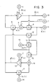
- FIG. 3 shows a central portion of the parameter adjusting unit 2, that is, an example of the block circuit diagram of the adjusting mechanical unit 201 for adaptively adjusting parameters.
- triangular blocks, square blocks and circular blocks indicate integrators, multipliers and adders, respectively. Double circular blocks indicate input or output terminals for signals.
- An integrator 3 integrates an input value of an adjustable parameter (t).
- a terminal 4 sets an initial value for the integrator 3.
- An input terminal 5 receives a vector signal ⁇ (t) from the external signal input processing unit 202.
- a multiplier 6 obtains a signal ( ⁇ T (t) ⁇ (t)) from ⁇ (t) and ⁇ (t).
- An input terminal 7 receives a signal s(t) from the external signal input processing unit 202.
- An adder 8 generates an error e(t) from s(t) and ( ⁇ T (t) ⁇ (t)).
- a multiplier 9 multiplies a signal ( ⁇ 2 (t) ⁇ (t) ⁇ (t)) by the error e(t).
- An output signal ⁇ 2 ⁇ (t) ⁇ (t)e(t) from the multiplier 9 is inverted and input to the integrator 3.
- An integrator 10 integrates an input value of a matrix gain ⁇ (t).
- a terminal 11 sets an initial value for the integrator 10.
- a multiplier 12 obtains a signal ( ⁇ (t) ⁇ (t))from ⁇ (t) and ⁇ (t).
- An input terminal 13 is for a scalar gain ⁇ 2(t).
- a multiplier 14 obtains the signal ⁇ 2(t) ⁇ (t) ⁇ (t) from ⁇ 2(t) and ( ⁇ (t) ⁇ (t)).
- a multiplier 15 obtains a signal ⁇ 2(t) ⁇ (t) ⁇ (t) ⁇ T (t) ⁇ (t) from ⁇ 2(t) ⁇ (t) ⁇ (t) and ⁇ (t) ⁇ (t).
- An input terminal 16 is for a scalar coefficient ⁇ 1(t).
- a multiplier 17 obtains a signal ( ⁇ 1(t) ⁇ (t)) from ⁇ 1(t) and ⁇ (t).
- An adder 18 obtains a signal ( ⁇ 1(t) ⁇ (t)- ⁇ 2(t) ⁇ (t) ⁇ (t) ⁇ T (t) ⁇ (t)) from ⁇ 1(t) ⁇ (t) and ⁇ 2(t) ⁇ (t) ⁇ (t) ⁇ T (t) ⁇ (t).
- the output signal from the adder 18 thus obtained is input to the integrator 10.
- An output terminal 19 outputs the signal ⁇ (t).
- the adjusting mechanical unit 201 receives signals ⁇ (t) and s(t), and outputs the signal ⁇ (t).
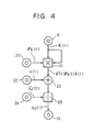
- FIG. 4 is a block circuit diagram showing a scaling method for the scalar gain ⁇ 2 (t).
- an input terminal 5 for the vector signal ⁇ (t) and an input terminal 20 for a matrix gain ⁇ S (t).
- a multiplier 21 obtains a signal ⁇ T (t) ⁇ S (t) ⁇ (t) from ⁇ (t) and ⁇ S (t).
- An input terminal 22 is for signal (t) which is utilized for scaling.
- An adder 23 obtains a signal (c(t) + ⁇ T (t) ⁇ S (t) ⁇ (t)) from an output signal from the multiplier 21 and the signal c(t).
- An input terminal 24 is for a scalar gain ⁇ 2′(t) which is an object of scaling.
- a divider obtains the scalar gain ⁇ 2(t) which is subjected to scaling from (c(t) + ⁇ T (t) ⁇ S (t) ⁇ (t)) and ⁇ 2′(t).
- FIG. 5 shows a block circuit diagram of a mechanism which further adjusts and modifies system parameters proportionately in the parameter adjusting unit 2.
- an adder 26 obtains a signal ⁇ (t)e(t) from ⁇ (t) and e(t).
- An input terminal 27 is for a matrix gain ⁇ P (t).
- a multiplier 28 obtains a signal ( ⁇ P (t) ⁇ (t)e(t)) from ( ⁇ (t)e(t)) and ⁇ P (t).
- An input terminal 29 is for a scalar gain ⁇ P ( t ) .
- a multiplier 30 obtains a signal ( ⁇ P (t) ⁇ P (t) ⁇ (t)e(t)) from ( ⁇ P (t) ⁇ (t)e(t)) and ⁇ P (t).
- ⁇ (t) ( 1 - ⁇ P (t) ⁇ T (t) ⁇ P (t) ⁇ (t))e(t) ( 21 ).
- a mechanism for adaptively adjusting parameters can be mathematically expressed as follows.
- the inventive method of adjusting a gain relative to the error equation expressed by expression (1) has been newly devised so as to minimize the evaluation function which is very significant from the viewpoint of engineering and is expressed by the following expression (30):
- the scalar gain ⁇ 2(t) can be provided with a scaling function, it is possible to eliminate an influence of the amount of the vector signal ⁇ (t) on the adjustable parameter ⁇ (t) by operating this function.
- FIG. 6 is a block diagram showing the present embodiment.
- an input unit IP1 outputs a signal which corresponds to a signal ⁇ (k).
- An input unit IP2 outputs a signal which corresponds to a signal e(k).
- the signal e(k) is obtained by dividing time in the signal e(t) obtained by expression (1) from signals ⁇ (t), s(t) and ⁇ (t), which the external signal input processing unit receives, into discrete values.
- FIG. 6 a processing procedure as shown in FIG. 7 is stored in a memory PMEM.
- a memory MEM stores data which are taken in, processed and the like.
- a processing unit CPU executes processing in accordance with the processing procedure stored in the memory PMEM.
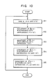
- FIG. 7 shows a flowchart in which the adaptive adjustment expressed in expressions (10′) - (13′) is performed using the signals ⁇ (k) and e(k) described above.
- the vector signal ⁇ (k) and the scalar error e(k) are taken in at step S1.
- an integral relationship and a proportional relationship are used together.
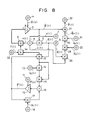
- the present embodiment differs from the embodiment in accordance with FIGS. 3 and 5 in that, in the present embodiment, ⁇ (t) which is different from ⁇ 2(t) used for the adjustment of ⁇ (t) is used as a scalar gain in the integral relationship.
- an input terminal 33 inputs ⁇ (t), and a multiplier 34 multiplies ⁇ (t) by ⁇ (t) ⁇ (t).
- expressions in the present embodiment differ from expressions (10) - (13) and (17) - (20), which correspond to FIGS. 3 and 5, respectively, in using the following expressions (33) and (34) in place of expressions (10) and (13).
- ⁇ (t) - ⁇ (t) ⁇ (t) ⁇ (t) e(t) (33) 0 ⁇ ⁇ 1 (t) ⁇ ⁇ , 0 ⁇ ⁇ 2 (t) ⁇ 2 ⁇ (t) ⁇ ⁇ (34).
- condition expressed in expression (34) is not shown in the block diagram, it is a condition necessary for properly adjusting the adjustable parameter ⁇ t (t).
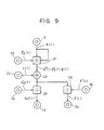
- FIG. 9 is a block circuit diagram showing a method of modification when the scaling of the scalar gain ⁇ (t) and the scalar coefficient ⁇ 2(t) shown in FIG. 8 is performed.
- This circuit further performs the scaling of ⁇ (t) using the scaling circuit shown in FIG. 4.
- FIG. 4 components which are identical to those in FIG. 4 are indicated by like numerals.
- FIG. 9 there is shown an input terminal 35 for a signal ⁇ ′(t).
- the signal ⁇ (t) is output to an input terminal 33.
- ⁇ (t) (1 - ⁇ P (t) ⁇ T (t) ⁇ P (t) ⁇ (t))e (t) (29).
- the error signal ⁇ (t) is used for the adjustment of ⁇ (t) and ⁇ P (t)
- the error signals e(t) and ⁇ (t) may be mixed such that e(t) and ⁇ (t) are used for ⁇ (t) and ⁇ P (t), respectively.
- the value of ⁇ (k)e(k) is taken in from the input units IP1 and IP2, and stored in the memory MEM (step S11).
- An operation processing for obtaining ⁇ P (k) is then performed by the processing unit CPU, and the operated result is stored in the memory MEM (step S12).
- step S13 An operation for obtaining ⁇ t (k) is then performed.
- the operated result is stored in the memory MEM, and is further sent to the processing unit 2 (step S13).
- the value of 0(k+1) is then similarly processed and stored (step S14).
- the value of ⁇ (k+1) is processed and stored (step S15).
- the performance of an adaptive system largely depends on the performance of a parameter adjusting unit having the role of adaptively adjusting system parameters.
- a parameter adjusting unit having the role of adaptively adjusting system parameters since it is possible to configure a parameter adjusting unit having the novel and excellent effects as described below, an adaptive system having a high performance which has not existed before can be constructed.
Landscapes
- Engineering & Computer Science (AREA)
- Health & Medical Sciences (AREA)
- Artificial Intelligence (AREA)
- Computer Vision & Pattern Recognition (AREA)
- Evolutionary Computation (AREA)
- Medical Informatics (AREA)
- Software Systems (AREA)
- Physics & Mathematics (AREA)
- General Physics & Mathematics (AREA)
- Automation & Control Theory (AREA)
- Feedback Control In General (AREA)
- Filters That Use Time-Delay Elements (AREA)
Applications Claiming Priority (4)
| Application Number | Priority Date | Filing Date | Title |
|---|---|---|---|
| JP1655289A JPH02196303A (ja) | 1989-01-25 | 1989-01-25 | 適応装置 |
| JP1655389A JPH02196304A (ja) | 1989-01-25 | 1989-01-25 | 適応装置 |
| JP16553/89 | 1989-01-25 | ||
| JP16552/89 | 1989-01-25 |
Publications (3)
| Publication Number | Publication Date |
|---|---|
| EP0380296A2 true EP0380296A2 (de) | 1990-08-01 |
| EP0380296A3 EP0380296A3 (en) | 1990-12-19 |
| EP0380296B1 EP0380296B1 (de) | 1996-03-27 |
Family
ID=26352913
Family Applications (1)
| Application Number | Title | Priority Date | Filing Date |
|---|---|---|---|
| EP90300692A Expired - Lifetime EP0380296B1 (de) | 1989-01-25 | 1990-01-23 | Selbstanpassende Vorrichtung |
Country Status (3)
| Country | Link |
|---|---|
| US (1) | US5305193A (de) |
| EP (1) | EP0380296B1 (de) |
| DE (1) | DE69026122T2 (de) |
Families Citing this family (2)
| Publication number | Priority date | Publication date | Assignee | Title |
|---|---|---|---|---|
| US6975753B2 (en) * | 2000-09-13 | 2005-12-13 | Canon Kabushiki Kaisha | Image processing apparatus, image processing method, program for implementing said method, and storage medium therefor |
| JP6485989B2 (ja) | 2011-12-26 | 2019-03-20 | キヤノン株式会社 | 画像形成装置およびその制御方法 |
Family Cites Families (5)
| Publication number | Priority date | Publication date | Assignee | Title |
|---|---|---|---|---|
| BE757241A (fr) * | 1969-10-20 | 1971-03-16 | Ceskoslovenska Akademie Ved | Dispositif du reseau de systemes de reglage adaptif |
| GB1583545A (en) * | 1976-08-04 | 1981-01-28 | Martin Sanchez J | Control systems |
| US4458321A (en) * | 1981-08-19 | 1984-07-03 | The Charles Stark Draper Laboratory, Inc. | Self-teaching robot feedback system |
| JPH07104715B2 (ja) * | 1984-01-18 | 1995-11-13 | 株式会社日立製作所 | パラメ−タの同定方法 |
| GB8727602D0 (en) * | 1987-11-25 | 1987-12-31 | Nat Res Dev | Industrial control systems |
-
1990
- 1990-01-23 DE DE69026122T patent/DE69026122T2/de not_active Expired - Fee Related
- 1990-01-23 EP EP90300692A patent/EP0380296B1/de not_active Expired - Lifetime
- 1990-01-24 US US07/469,375 patent/US5305193A/en not_active Expired - Lifetime
Also Published As
| Publication number | Publication date |
|---|---|
| US5305193A (en) | 1994-04-19 |
| EP0380296B1 (de) | 1996-03-27 |
| EP0380296A3 (en) | 1990-12-19 |
| DE69026122T2 (de) | 1996-08-29 |
| DE69026122D1 (de) | 1996-05-02 |
Similar Documents
| Publication | Publication Date | Title |
|---|---|---|
| EP0104845B1 (de) | Vorrichtung zum Steuern von Prozessen | |
| US5053866A (en) | Method and an associated apparatus for calibrating a color digital hardcopy device | |
| EP0377678B1 (de) | Regelungssystem | |
| EP0345871B1 (de) | Vorrichtung zum Wiedergeben von digitalisierten Bildern mittels einer Fehlerwiederherstellung mit einer geneigten Ebene | |
| US4634946A (en) | Apparatus and method for predictive control of a dynamic system | |
| US20040249483A1 (en) | Multiple-input/multiple-output control blocks with non-linear predictive capabilities | |
| JP4624790B2 (ja) | 音場表現処理方法およびシステム | |
| JP2002049409A (ja) | プロセス制御システムにおける適応推定モデル | |
| DK0632914T3 (da) | Fremgangsmåde og apparatur til adaptiv interpolation af et digitalt billede | |
| US5233412A (en) | Color image processing device which produces a corrected color image signal | |
| US5631979A (en) | Pixel value estimation technique using non-linear prediction | |
| EP0380296A2 (de) | Selbstanpassende Vorrichtung | |
| RU2109317C1 (ru) | Адаптивная система управления | |
| US5307088A (en) | Method and apparatus of encoding color image information | |
| EP0422809B1 (de) | Adaptive Anordnung | |
| KR20020029898A (ko) | 적응형 필터링 방법 및 관련 장치 | |
| US20240412052A1 (en) | Data processing method and data processing device using supplemented neural network quantization operation | |
| EP0606656A2 (de) | Steuerungsmethode zur Erreichung eines Sollwertes | |
| US4758889A (en) | Value correction method | |
| US20050065621A1 (en) | Methods of designing optimal linear controllers | |
| JPH04264499A (ja) | 音声信号のスペクトル分析方法とその装置 | |
| JPS5952361A (ja) | 画像信号処理における演算方式 | |
| JPH11275378A (ja) | ホワイトバランス調整方法および装置 | |
| US20230008014A1 (en) | Data processing device, data-processing method and recording media | |
| JPH04302302A (ja) | 2自由度制御装置 |
Legal Events
| Date | Code | Title | Description |
|---|---|---|---|
| PUAI | Public reference made under article 153(3) epc to a published international application that has entered the european phase |
Free format text: ORIGINAL CODE: 0009012 |
|
| AK | Designated contracting states |
Kind code of ref document: A2 Designated state(s): DE FR GB |
|
| PUAL | Search report despatched |
Free format text: ORIGINAL CODE: 0009013 |
|
| AK | Designated contracting states |
Kind code of ref document: A3 Designated state(s): DE FR GB |
|
| 17P | Request for examination filed |
Effective date: 19901231 |
|
| 17Q | First examination report despatched |
Effective date: 19930524 |
|
| GRAA | (expected) grant |
Free format text: ORIGINAL CODE: 0009210 |
|
| AK | Designated contracting states |
Kind code of ref document: B1 Designated state(s): DE FR GB |
|
| REF | Corresponds to: |
Ref document number: 69026122 Country of ref document: DE Date of ref document: 19960502 |
|
| ET | Fr: translation filed | ||
| PLBE | No opposition filed within time limit |
Free format text: ORIGINAL CODE: 0009261 |
|
| STAA | Information on the status of an ep patent application or granted ep patent |
Free format text: STATUS: NO OPPOSITION FILED WITHIN TIME LIMIT |
|
| 26N | No opposition filed | ||
| REG | Reference to a national code |
Ref country code: GB Ref legal event code: IF02 |
|
| PGFP | Annual fee paid to national office [announced via postgrant information from national office to epo] |
Ref country code: GB Payment date: 20080128 Year of fee payment: 19 Ref country code: DE Payment date: 20080131 Year of fee payment: 19 |
|
| PGFP | Annual fee paid to national office [announced via postgrant information from national office to epo] |
Ref country code: FR Payment date: 20080123 Year of fee payment: 19 |
|
| GBPC | Gb: european patent ceased through non-payment of renewal fee |
Effective date: 20090123 |
|
| PG25 | Lapsed in a contracting state [announced via postgrant information from national office to epo] |
Ref country code: DE Free format text: LAPSE BECAUSE OF NON-PAYMENT OF DUE FEES Effective date: 20090801 |
|
| REG | Reference to a national code |
Ref country code: FR Ref legal event code: ST Effective date: 20091030 |
|
| PG25 | Lapsed in a contracting state [announced via postgrant information from national office to epo] |
Ref country code: GB Free format text: LAPSE BECAUSE OF NON-PAYMENT OF DUE FEES Effective date: 20090123 |
|
| PG25 | Lapsed in a contracting state [announced via postgrant information from national office to epo] |
Ref country code: FR Free format text: LAPSE BECAUSE OF NON-PAYMENT OF DUE FEES Effective date: 20090202 |