EP0380020A2 - Rouleau - Google Patents
Rouleau Download PDFInfo
- Publication number
- EP0380020A2 EP0380020A2 EP90101209A EP90101209A EP0380020A2 EP 0380020 A2 EP0380020 A2 EP 0380020A2 EP 90101209 A EP90101209 A EP 90101209A EP 90101209 A EP90101209 A EP 90101209A EP 0380020 A2 EP0380020 A2 EP 0380020A2
- Authority
- EP
- European Patent Office
- Prior art keywords
- bottom roller
- tires
- rubber tires
- roller according
- support
- Prior art date
- Legal status (The legal status is an assumption and is not a legal conclusion. Google has not performed a legal analysis and makes no representation as to the accuracy of the status listed.)
- Granted
Links
Images


Classifications
-
- A—HUMAN NECESSITIES
- A01—AGRICULTURE; FORESTRY; ANIMAL HUSBANDRY; HUNTING; TRAPPING; FISHING
- A01B—SOIL WORKING IN AGRICULTURE OR FORESTRY; PARTS, DETAILS, OR ACCESSORIES OF AGRICULTURAL MACHINES OR IMPLEMENTS, IN GENERAL
- A01B29/00—Rollers
- A01B29/04—Rollers with non-smooth surface formed of rotatably-mounted rings or discs or with projections or ribs on the roller body; Land packers
- A01B29/041—Rollers with non-smooth surface formed of rotatably-mounted rings or discs or with projections or ribs on the roller body; Land packers of "Cambridge"-type, i.e. the soil-pressing rings being stacked on a shaft
- A01B29/043—Tire-packers
Definitions
- the invention relates to a floor roller according to the preambles of claims 1 and 2.
- Such a floor roller is known for example from EP-OS 02 64 621.
- the invention is based, to achieve an optimally pressed seed bed with great ease of movement of the machine, in particular for single grain seeds.
- an optimal, pressed seed bed is obtained in the simplest manner, in which the seed grains can be deposited in the furrows drawn by the coulters.
- the rubber tires can be adapted to different row spacings, so that the rubber tires always compress the area in which the seeds are deposited.
- the rubber tires are each separately stored and individually rotatably attached to a central support frame with separate suspensions. This makes it possible for the rubber tires to be arranged at different distances from one another, so that it is very easy to adapt to different row distances for the different cultures.
- the rubber tires are arranged on a central and rotatably mounted support tube, spacer rings being arranged in each case between the adjacent rubber tires. This makes it possible to convert the bottom rollers already in practice according to the invention.
- bottom rollers with different distances between the tires and seeders with different numbers of rows can be used in the device combination.
- the soil cultivation combination can be used by replacing the individual soil rollers or by converting the soil roller with a different number of tires, both when used with a precision seed drill and with a conventional grain seed drill.
- the rubber tire roller it is also possible for the rubber tire roller to be exchanged for other bottom rollers, for example packer rollers, bar rollers, etc.
- the invention provides that the rubber tires are fastened on rim-like support elements that between the rim-like support elements and the rotatable support frame (profile tube) are arranged clamp holder elements with which the rubber tires can be clamped and moved as desired on the support frame.
- the clamping bracket elements are preferably made as clamping brackets educated.
- the invention provides that the clamp mounting elements have a width which is greater than the width of the tires. This creates the prerequisite that in each case clamping devices, for example clamping screws, can be arranged on the clamping bracket elements in their lateral outer region, so that even with this tight arrangement of the rubber tires they can be clamped next to one another by means of a socket wrench.
- the clamping devices should be at least approximately to the side of the tires.
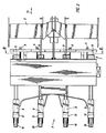
- the bottom roller 1 is part of the sowing and tillage combination according to FIG. 1, which consists of a soil cultivator arranged in front of the bottom roller 1, for example a rotary harrow 2, the bottom roller designed as a follower roller 1 and the subordinate precision seed drill 3.
- the rotary harrow 2 has the driven tillage tools 4.
- the fertilizer container 5 is also saddled on the bottom roller 1, from which the fertilizer coulters 6, which are arranged between the bottom roller 1 and the tillage implement 2, are fed via pipes to the fertilizer.
- the suction blower 7 is arranged behind the fertilizer container 5, via which a vacuum is generated for the separating mechanism of the precision seed drills of the precision seed drill 3.
- the precision seed drills of the precision seed drill 3 each have a coulter 8 with which furrows are drawn in the soil 9 and in which the seed is deposited.
- a pressure roller 10 is arranged behind the coulter 8.
- the ground roller 1 has the same number of rubber tires 11 as the precision seeder 3 has coulters 8.
- Each sowing device 12 of the precision seed drill 3 is assigned a coulter 8.
- the rubber tires 11 of the ground roller 1 are arranged in alignment in the direction of travel 13 in front of the coulters 8 of the precision seed drill 3.
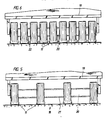
- the rubber tires 11 of the floor roller 1 are each mounted separately on rims and individually with separate suspensions 14 and clamping tabs 15 on the central support frame 16 of the floor roller 1 attached. This makes it possible for the rubber tires 11 to be arranged at different distances from one another by loosening the clamping tabs 15. This makes it possible to adapt to different row spacings of the coulters 8 of the precision seed drill 3 for different crops.
- the coulters 8 of the precision seed drill 3 are arranged next to each other in very narrow row spacings, it is possible to arrange a plurality of rubber tires 11 with separate suspensions 14 and clamping tabs 15 on the central frame 16, as shown in FIG. 4.
- a leading rubber tire 11 of the trailing roller 17 is again assigned to a trailing coulter 8 of a precision seed drill 3.
- support rings can be arranged in a known and therefore not shown manner, so that one achieves sufficient consolidation of the soil, as described for example in European patent application 02 45 648.
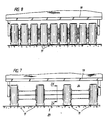
- the bottom roller 18 according to FIG. 5 can also be used in the ordering and sowing combination according to FIG. 1.
- This bottom roller 18 consists of the central support frame 19, the central support tube 20 and the rubber tires 11. Within these rubber tires 11 support rings can again be arranged, as described for example in European patent application 02 45 648. Spacer rings 21 are arranged between the individual rubber tires 11 and determine the distance between the adjacent rubber tires 11.
- the same number of rubber tires 11 as the coulters 8 of an precision seed drill 3 is again provided, the rubber tires 11 being arranged in alignment with the coulters 8 of the precision seed drill 3 when viewed in the direction of travel.
- bottom roller for example packer rollers, bar roller etc.
- bottom roller 1 with rubber tires 11.
- the ground roller 23 according to FIG. 7 can also be used in the tillage, sowing and / or ordering combination.
- This bottom roller 23 consists of the central support frame 19, the rotatable support frame 24, which is designed as a square tube, and the rubber tires 11.
- the three support rings 25 are arranged within the rubber tires 11.
- the rubber tires 11 are fastened on rim-like support elements 26.
- Arranged between the rim-like support elements and the square tube 24 are the clamping bracket elements designed as clamping brackets 27, with which the rubber tires can be clamped and displaced at fixed intervals on the square tube 24.
- the clamping bracket 27 are clamped by means of the clamping screws 28.
- the clamping bracket 27 have a greater width than the width of the tires.
- the clamping screws 28 are arranged in the holes 29 which are located in the clamping brackets 27 in their lateral outer regions.
- the clamping screws 28 are located at least approximately laterally next to the tires 11.
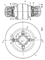
- the rim-like support elements 26 furthermore have the support rings or support disks 30, which are clamped by the screw 31.
- each clamping bracket 27 is welded on one side to the spacer ring 32, while the other end 33 is angled and is pulled against the welded end 34 of the other clamping bracket by means of the clamping screw 28.
- the rubber tires 11 can be laterally displaced on the square tube 24 and, after being adjusted to the desired distance from one another, can be clamped again.
- the bottom roller according to FIG. 7 can easily be converted into the bottom roller according to FIG. 8.
- the fact that the clamping screws 28 are located to the side of the tires 11 makes it possible for the clamping screws 28 to be loosened or tightened by means of a socket wrench even when the tires 11 are arranged closely next to one another as shown in FIG.
Landscapes
- Life Sciences & Earth Sciences (AREA)
- Engineering & Computer Science (AREA)
- Mechanical Engineering (AREA)
- Soil Sciences (AREA)
- Environmental Sciences (AREA)
- Sowing (AREA)
- Soil Working Implements (AREA)
Applications Claiming Priority (2)
| Application Number | Priority Date | Filing Date | Title |
|---|---|---|---|
| DE3901883A DE3901883A1 (de) | 1989-01-23 | 1989-01-23 | Bodenwalze |
| DE3901883 | 1989-01-23 |
Publications (3)
| Publication Number | Publication Date |
|---|---|
| EP0380020A2 true EP0380020A2 (fr) | 1990-08-01 |
| EP0380020A3 EP0380020A3 (fr) | 1991-09-18 |
| EP0380020B1 EP0380020B1 (fr) | 1993-11-24 |
Family
ID=6372611
Family Applications (1)
| Application Number | Title | Priority Date | Filing Date |
|---|---|---|---|
| EP90101209A Expired - Lifetime EP0380020B1 (fr) | 1989-01-23 | 1990-01-22 | Rouleau |
Country Status (2)
| Country | Link |
|---|---|
| EP (1) | EP0380020B1 (fr) |
| DE (2) | DE3901883A1 (fr) |
Cited By (6)
| Publication number | Priority date | Publication date | Assignee | Title |
|---|---|---|---|---|
| FR2679102A1 (fr) * | 1991-07-18 | 1993-01-22 | Amazonen Werke Dreyer H | Combinaison fermee comprenant un distributeur d'engrais et un semoir. |
| EP0682854A1 (fr) * | 1994-05-17 | 1995-11-22 | Kuhn S.A. | Rouleau de travail du sol à usage agricole et machine agricole utilisant un tel rouleau |
| EP1856964A1 (fr) | 2006-05-17 | 2007-11-21 | Alois Pöttinger Maschinenfabrik Ges. m.b.H. | Semoir |
| CN103786807A (zh) * | 2014-02-14 | 2014-05-14 | 江苏省农业科学院农业资源与环境研究所 | 一种自走式农用三轮镇压机 |
| CN109716888A (zh) * | 2019-01-31 | 2019-05-07 | 滨州市作物研究所 | 一种两高四低高低畦种植施肥播种一体机 |
| EP3636057A1 (fr) * | 2018-10-12 | 2020-04-15 | Otico | Pneumatique de rouleau agricole |
Families Citing this family (1)
| Publication number | Priority date | Publication date | Assignee | Title |
|---|---|---|---|---|
| DE102005047014A1 (de) * | 2005-09-30 | 2007-04-05 | Heiss, Andreas | Kombinierte landwirtschaftliche Maschine zur Bodenbearbeitung und Aussaat |
Citations (8)
| Publication number | Priority date | Publication date | Assignee | Title |
|---|---|---|---|---|
| FR2189226A1 (fr) * | 1972-06-16 | 1974-01-25 | Pouyaud Andre | |
| EP0216050A2 (fr) * | 1985-09-21 | 1987-04-01 | Amazonen-Werke H. Dreyer GmbH & Co. KG | Combinaisons de préparation du sol |
| EP0223134A1 (fr) * | 1985-11-09 | 1987-05-27 | Amazonen-Werke H. Dreyer GmbH & Co. KG | Rouleau agraire |
| EP0233134A1 (fr) * | 1986-02-13 | 1987-08-19 | United Technologies Corporation | Méthode et appareil pour le moulage utilisant un polymère solide et fluide |
| EP0245648A1 (fr) * | 1986-05-13 | 1987-11-19 | Amazonen-Werke H. Dreyer GmbH & Co. KG | Rouleau de terre |
| EP0264621A1 (fr) * | 1986-10-02 | 1988-04-27 | Amazonen-Werke H. Dreyer GmbH & Co. KG | Combinaison d'instruments pour travaux agricoles |
| EP0299190A1 (fr) * | 1987-07-17 | 1989-01-18 | Amazonen-Werke H. Dreyer GmbH & Co. KG | Rouleau compresseur |
| EP0299290A1 (fr) * | 1987-07-17 | 1989-01-18 | Amazonen-Werke H. Dreyer GmbH & Co. KG | Rouleau de travail du sol |
-
1989
- 1989-01-23 DE DE3901883A patent/DE3901883A1/de not_active Withdrawn
-
1990
- 1990-01-22 EP EP90101209A patent/EP0380020B1/fr not_active Expired - Lifetime
- 1990-01-22 DE DE90101209T patent/DE59003563D1/de not_active Expired - Fee Related
Patent Citations (8)
| Publication number | Priority date | Publication date | Assignee | Title |
|---|---|---|---|---|
| FR2189226A1 (fr) * | 1972-06-16 | 1974-01-25 | Pouyaud Andre | |
| EP0216050A2 (fr) * | 1985-09-21 | 1987-04-01 | Amazonen-Werke H. Dreyer GmbH & Co. KG | Combinaisons de préparation du sol |
| EP0223134A1 (fr) * | 1985-11-09 | 1987-05-27 | Amazonen-Werke H. Dreyer GmbH & Co. KG | Rouleau agraire |
| EP0233134A1 (fr) * | 1986-02-13 | 1987-08-19 | United Technologies Corporation | Méthode et appareil pour le moulage utilisant un polymère solide et fluide |
| EP0245648A1 (fr) * | 1986-05-13 | 1987-11-19 | Amazonen-Werke H. Dreyer GmbH & Co. KG | Rouleau de terre |
| EP0264621A1 (fr) * | 1986-10-02 | 1988-04-27 | Amazonen-Werke H. Dreyer GmbH & Co. KG | Combinaison d'instruments pour travaux agricoles |
| EP0299190A1 (fr) * | 1987-07-17 | 1989-01-18 | Amazonen-Werke H. Dreyer GmbH & Co. KG | Rouleau compresseur |
| EP0299290A1 (fr) * | 1987-07-17 | 1989-01-18 | Amazonen-Werke H. Dreyer GmbH & Co. KG | Rouleau de travail du sol |
Cited By (8)
| Publication number | Priority date | Publication date | Assignee | Title |
|---|---|---|---|---|
| FR2679102A1 (fr) * | 1991-07-18 | 1993-01-22 | Amazonen Werke Dreyer H | Combinaison fermee comprenant un distributeur d'engrais et un semoir. |
| EP0682854A1 (fr) * | 1994-05-17 | 1995-11-22 | Kuhn S.A. | Rouleau de travail du sol à usage agricole et machine agricole utilisant un tel rouleau |
| FR2719969A1 (fr) * | 1994-05-17 | 1995-11-24 | Kuhn Sa | Rouleau de travail du sol à usage agricole et machine agricole utilisant un tel rouleau. |
| EP1856964A1 (fr) | 2006-05-17 | 2007-11-21 | Alois Pöttinger Maschinenfabrik Ges. m.b.H. | Semoir |
| CN103786807A (zh) * | 2014-02-14 | 2014-05-14 | 江苏省农业科学院农业资源与环境研究所 | 一种自走式农用三轮镇压机 |
| EP3636057A1 (fr) * | 2018-10-12 | 2020-04-15 | Otico | Pneumatique de rouleau agricole |
| FR3087084A1 (fr) * | 2018-10-12 | 2020-04-17 | Otico | Pneumatique de rouleau agricole |
| CN109716888A (zh) * | 2019-01-31 | 2019-05-07 | 滨州市作物研究所 | 一种两高四低高低畦种植施肥播种一体机 |
Also Published As
| Publication number | Publication date |
|---|---|
| DE59003563D1 (de) | 1994-01-05 |
| DE3901883A1 (de) | 1990-07-26 |
| EP0380020B1 (fr) | 1993-11-24 |
| EP0380020A3 (fr) | 1991-09-18 |
Similar Documents
| Publication | Publication Date | Title |
|---|---|---|
| DE2930550C2 (de) | Drillmaschine | |
| DE2259545C2 (de) | Bodenbearbeitungsmaschine | |
| DE1557752B2 (de) | Bodenbearbeitungsmaschine | |
| EP0380020B1 (fr) | Rouleau | |
| EP0373467B1 (fr) | Machine combinée | |
| DE2922185C2 (de) | Drillmaschine | |
| EP0445582B1 (fr) | Machine pour travailler le sol | |
| EP0327869B1 (fr) | Machine combinée de culture et de semis | |
| EP0191871B1 (fr) | Machine à cultiver | |
| DE3933345A1 (de) | Drillmaschine, insbesondere zur direktsaat | |
| DE19839880A1 (de) | Strohstriegel | |
| CH711399B1 (de) | Landwirtschaftliche Maschine zum Bearbeiten eines Bodens und zum Ausbringen von Saatgut. | |
| EP0407724B1 (fr) | Semoir monograine | |
| EP0356606B1 (fr) | Semoir monograine | |
| EP3692776A1 (fr) | Dispositif de traitement du sol agricole | |
| EP0548890A1 (fr) | Méthode de semis direct et dispositif pour l'application de cette méthode | |
| DE4339443A1 (de) | Verfahren zum Aussäen von Saatgut auf zur Saat unvorbereiteten Böden ohne konventionelle Herrichtung zu einem Saatbett | |
| DE3130910A1 (de) | Breitsaatverfahren und -vorrichtung | |
| DE3141078C1 (de) | Drillmaschine | |
| EP0075133B1 (fr) | Dispositif de semis en bandes | |
| DE3723616A1 (de) | Bodenbearbeitungsgeraet mit angebauter saemaschine | |
| DE2734676C3 (de) | Rasenperforationsmaschine | |
| DE3722842A1 (de) | Bodenbearbeitungsgeraet mit saatgutablage | |
| AT258626B (de) | Vorrichtung zur gleichmäßig tiefen Einbringung des Saatgutes in den Boden | |
| AT3991U1 (de) | Bodenbearbeitungsmaschine |
Legal Events
| Date | Code | Title | Description |
|---|---|---|---|
| PUAI | Public reference made under article 153(3) epc to a published international application that has entered the european phase |
Free format text: ORIGINAL CODE: 0009012 |
|
| AK | Designated contracting states |
Kind code of ref document: A2 Designated state(s): DE FR GB IT NL |
|
| PUAL | Search report despatched |
Free format text: ORIGINAL CODE: 0009013 |
|
| AK | Designated contracting states |
Kind code of ref document: A3 Designated state(s): DE FR GB IT NL |
|
| 17P | Request for examination filed |
Effective date: 19911212 |
|
| 17Q | First examination report despatched |
Effective date: 19920318 |
|
| GRAA | (expected) grant |
Free format text: ORIGINAL CODE: 0009210 |
|
| AK | Designated contracting states |
Kind code of ref document: B1 Designated state(s): DE FR GB IT NL |
|
| PG25 | Lapsed in a contracting state [announced via postgrant information from national office to epo] |
Ref country code: IT Free format text: LAPSE BECAUSE OF FAILURE TO SUBMIT A TRANSLATION OF THE DESCRIPTION OR TO PAY THE FEE WITHIN THE PRESCRIBED TIME-LIMIT;WARNING: LAPSES OF ITALIAN PATENTS WITH EFFECTIVE DATE BEFORE 2007 MAY HAVE OCCURRED AT ANY TIME BEFORE 2007. THE CORRECT EFFECTIVE DATE MAY BE DIFFERENT FROM THE ONE RECORDED. Effective date: 19931124 |
|
| ET | Fr: translation filed | ||
| PGFP | Annual fee paid to national office [announced via postgrant information from national office to epo] |
Ref country code: FR Payment date: 19931231 Year of fee payment: 5 |
|
| REF | Corresponds to: |
Ref document number: 59003563 Country of ref document: DE Date of ref document: 19940105 |
|
| PGFP | Annual fee paid to national office [announced via postgrant information from national office to epo] |
Ref country code: DE Payment date: 19940124 Year of fee payment: 5 |
|
| PGFP | Annual fee paid to national office [announced via postgrant information from national office to epo] |
Ref country code: NL Payment date: 19940131 Year of fee payment: 5 |
|
| PGFP | Annual fee paid to national office [announced via postgrant information from national office to epo] |
Ref country code: GB Payment date: 19940208 Year of fee payment: 5 |
|
| GBT | Gb: translation of ep patent filed (gb section 77(6)(a)/1977) |
Effective date: 19940301 |
|
| PLBE | No opposition filed within time limit |
Free format text: ORIGINAL CODE: 0009261 |
|
| STAA | Information on the status of an ep patent application or granted ep patent |
Free format text: STATUS: NO OPPOSITION FILED WITHIN TIME LIMIT |
|
| 26N | No opposition filed | ||
| PG25 | Lapsed in a contracting state [announced via postgrant information from national office to epo] |
Ref country code: GB Effective date: 19950122 |
|
| PG25 | Lapsed in a contracting state [announced via postgrant information from national office to epo] |
Ref country code: NL Effective date: 19950801 |
|
| GBPC | Gb: european patent ceased through non-payment of renewal fee |
Effective date: 19950122 |
|
| PG25 | Lapsed in a contracting state [announced via postgrant information from national office to epo] |
Ref country code: FR Effective date: 19950929 |
|
| NLV4 | Nl: lapsed or anulled due to non-payment of the annual fee |
Effective date: 19950801 |
|
| PG25 | Lapsed in a contracting state [announced via postgrant information from national office to epo] |
Ref country code: DE Effective date: 19951003 |
|
| REG | Reference to a national code |
Ref country code: FR Ref legal event code: ST |