EP0377262A2 - Kompaktes und effizientes Tiefbass-Lautsprechersystem und Verfahren zum Einbau in Gehäusestrukturen - Google Patents
Kompaktes und effizientes Tiefbass-Lautsprechersystem und Verfahren zum Einbau in Gehäusestrukturen Download PDFInfo
- Publication number
- EP0377262A2 EP0377262A2 EP89250128A EP89250128A EP0377262A2 EP 0377262 A2 EP0377262 A2 EP 0377262A2 EP 89250128 A EP89250128 A EP 89250128A EP 89250128 A EP89250128 A EP 89250128A EP 0377262 A2 EP0377262 A2 EP 0377262A2
- Authority
- EP
- European Patent Office
- Prior art keywords
- enclosure
- partition
- loudspeaker system
- mounting
- front panel
- Prior art date
- Legal status (The legal status is an assumption and is not a legal conclusion. Google has not performed a legal analysis and makes no representation as to the accuracy of the status listed.)
- Withdrawn
Links
- 238000005192 partition Methods 0.000 title claims abstract description 90
- 238000009434 installation Methods 0.000 title claims abstract description 14
- 238000000034 method Methods 0.000 title claims description 15
- 230000008878 coupling Effects 0.000 claims abstract description 17
- 238000010168 coupling process Methods 0.000 claims abstract description 17
- 238000005859 coupling reaction Methods 0.000 claims abstract description 17
- 230000006835 compression Effects 0.000 claims abstract description 13
- 238000007906 compression Methods 0.000 claims abstract description 13
- 230000002463 transducing effect Effects 0.000 claims description 25
- 230000036961 partial effect Effects 0.000 claims description 9
- 238000002955 isolation Methods 0.000 claims description 4
- 210000000188 diaphragm Anatomy 0.000 claims 22
- 238000010586 diagram Methods 0.000 description 7
- 238000002474 experimental method Methods 0.000 description 7
- 230000005540 biological transmission Effects 0.000 description 5
- 238000010276 construction Methods 0.000 description 4
- 239000000463 material Substances 0.000 description 3
- 239000011435 rock Substances 0.000 description 3
- 230000000694 effects Effects 0.000 description 2
- 230000005855 radiation Effects 0.000 description 2
- 230000002829 reductive effect Effects 0.000 description 2
- 208000036366 Sensation of pressure Diseases 0.000 description 1
- 230000001133 acceleration Effects 0.000 description 1
- 239000000853 adhesive Substances 0.000 description 1
- 230000001070 adhesive effect Effects 0.000 description 1
- 230000002238 attenuated effect Effects 0.000 description 1
- 239000004035 construction material Substances 0.000 description 1
- 230000003247 decreasing effect Effects 0.000 description 1
- 230000005284 excitation Effects 0.000 description 1
- 230000003455 independent Effects 0.000 description 1
- 230000002452 interceptive effect Effects 0.000 description 1
- 239000000725 suspension Substances 0.000 description 1
- 239000002023 wood Substances 0.000 description 1
Images


Classifications
-
- H—ELECTRICITY
- H04—ELECTRIC COMMUNICATION TECHNIQUE
- H04R—LOUDSPEAKERS, MICROPHONES, GRAMOPHONE PICK-UPS OR LIKE ACOUSTIC ELECTROMECHANICAL TRANSDUCERS; DEAF-AID SETS; PUBLIC ADDRESS SYSTEMS
- H04R1/00—Details of transducers, loudspeakers or microphones
- H04R1/20—Arrangements for obtaining desired frequency or directional characteristics
- H04R1/22—Arrangements for obtaining desired frequency or directional characteristics for obtaining desired frequency characteristic only
- H04R1/28—Transducer mountings or enclosures modified by provision of mechanical or acoustic impedances, e.g. resonator, damping means
- H04R1/2807—Enclosures comprising vibrating or resonating arrangements
- H04R1/2838—Enclosures comprising vibrating or resonating arrangements of the bandpass type
- H04R1/2842—Enclosures comprising vibrating or resonating arrangements of the bandpass type for loudspeaker transducers
-
- H—ELECTRICITY
- H04—ELECTRIC COMMUNICATION TECHNIQUE
- H04R—LOUDSPEAKERS, MICROPHONES, GRAMOPHONE PICK-UPS OR LIKE ACOUSTIC ELECTROMECHANICAL TRANSDUCERS; DEAF-AID SETS; PUBLIC ADDRESS SYSTEMS
- H04R1/00—Details of transducers, loudspeakers or microphones
- H04R1/02—Casings; Cabinets ; Supports therefor; Mountings therein
- H04R1/025—Arrangements for fixing loudspeaker transducers, e.g. in a box, furniture
-
- H—ELECTRICITY
- H04—ELECTRIC COMMUNICATION TECHNIQUE
- H04R—LOUDSPEAKERS, MICROPHONES, GRAMOPHONE PICK-UPS OR LIKE ACOUSTIC ELECTROMECHANICAL TRANSDUCERS; DEAF-AID SETS; PUBLIC ADDRESS SYSTEMS
- H04R1/00—Details of transducers, loudspeakers or microphones
- H04R1/20—Arrangements for obtaining desired frequency or directional characteristics
- H04R1/22—Arrangements for obtaining desired frequency or directional characteristics for obtaining desired frequency characteristic only
- H04R1/28—Transducer mountings or enclosures modified by provision of mechanical or acoustic impedances, e.g. resonator, damping means
- H04R1/2807—Enclosures comprising vibrating or resonating arrangements
- H04R1/283—Enclosures comprising vibrating or resonating arrangements using a passive diaphragm
- H04R1/2834—Enclosures comprising vibrating or resonating arrangements using a passive diaphragm for loudspeaker transducers
-
- H—ELECTRICITY
- H04—ELECTRIC COMMUNICATION TECHNIQUE
- H04R—LOUDSPEAKERS, MICROPHONES, GRAMOPHONE PICK-UPS OR LIKE ACOUSTIC ELECTROMECHANICAL TRANSDUCERS; DEAF-AID SETS; PUBLIC ADDRESS SYSTEMS
- H04R1/00—Details of transducers, loudspeakers or microphones
- H04R1/20—Arrangements for obtaining desired frequency or directional characteristics
- H04R1/22—Arrangements for obtaining desired frequency or directional characteristics for obtaining desired frequency characteristic only
- H04R1/28—Transducer mountings or enclosures modified by provision of mechanical or acoustic impedances, e.g. resonator, damping means
- H04R1/2807—Enclosures comprising vibrating or resonating arrangements
- H04R1/2838—Enclosures comprising vibrating or resonating arrangements of the bandpass type
- H04R1/2846—Vents, i.e. ports, e.g. shape thereof or tuning thereof with damping material
- H04R1/2849—Vents, i.e. ports, e.g. shape thereof or tuning thereof with damping material for loudspeaker transducers
-
- H—ELECTRICITY
- H04—ELECTRIC COMMUNICATION TECHNIQUE
- H04R—LOUDSPEAKERS, MICROPHONES, GRAMOPHONE PICK-UPS OR LIKE ACOUSTIC ELECTROMECHANICAL TRANSDUCERS; DEAF-AID SETS; PUBLIC ADDRESS SYSTEMS
- H04R2201/00—Details of transducers, loudspeakers or microphones covered by H04R1/00 but not provided for in any of its subgroups
- H04R2201/02—Details casings, cabinets or mounting therein for transducers covered by H04R1/02 but not provided for in any of its subgroups
- H04R2201/021—Transducers or their casings adapted for mounting in or to a wall or ceiling
-
- H—ELECTRICITY
- H04—ELECTRIC COMMUNICATION TECHNIQUE
- H04R—LOUDSPEAKERS, MICROPHONES, GRAMOPHONE PICK-UPS OR LIKE ACOUSTIC ELECTROMECHANICAL TRANSDUCERS; DEAF-AID SETS; PUBLIC ADDRESS SYSTEMS
- H04R2499/00—Aspects covered by H04R or H04S not otherwise provided for in their subgroups
- H04R2499/10—General applications
- H04R2499/13—Acoustic transducers and sound field adaptation in vehicles
Definitions
- the present invention relates to a sub-woofer loudspeaker system and method for compact, efficient installation in structural partitions, such as walls, ceilings, floors, or automobile panels.
- the principles of this invention are also applicable to installing such a speaker system in panels of an automobile interior.
- a loudspeaker system for installation in a space defined by a front panel and an enclosed area behind the front panel of a structural partition.
- the structural partition is a wall, ceiling or floor having a front panel fronting a listening area and having a rear panel.
- Electroacoustical transducing means is provided which has a two sided vibratory diaphragm with means provided for coupling an electrical signal to the electroacoustical transducing means for driving it.
- Enclosure means is provided for mounting the electroacoustical transducing means within the partition such that one side of the vibratory diaphragm is in contact with air outside the enclosure means, with the enclosure means being configured to substantially enclose and define a specific volume of air within the enclosure having a predefined acoustic compliance and which is in contact with the other side of the vibratory diaphragm of the electroacoustical transducing means.
- Means are provided for mounting the enclosure means to the structural partition such that the enclosure means extends into the space behind the front panel of the partition so that the one side of the vibratory diaphragm contacts a volume of air outside the enclosure means within the space behind the front panel of the partition.
- a passive radiating means characterized by having a specific acoustic mass is provided for coupling the specific volume of air enclosed by the enclosure means to the air outside the enclosure means in the listening area.
- the electroacoustical transducer itself and the enclosure are concealed within the structural partition, while the volume of air outside the enclosure means within the space behind the front panel of the partition is substantially acoustically isolated over the approximate frequency range of operation of the electroacoustical transducing means from the volume of air outside the enclosure means within the listening area.
- a compression plate is provided in spaced relationship to and facing the one side of the vibratory diaphram in contact with air outside the enclosure to provide isolation of the rear panel of the partition from the vibratory diaphram.
- An adequate conventional cabinet size for obtaining deep bass response from an eight inch driver with moderate efficiency might be 1.5 cubic feet, at a minimum. Enclosure wall thicknesses of 1/16 inch would have to be considered a minimum. This would indicate that a cabinet over 50 inches high would be required to achieve the required volume for a single eight inch driver, assuming the driver itself was shallow enough to fit.
- the frequency range of the band-pass may be extended by using a port in the sealed cavity also.
- This second port is tuned to a different frequency such that the phase of the acoustic outputs of the two ports adds where they overlap to create a smooth overall response.
- FIG. 3A there is shown a diagrammatic cross-sectional view illustrating the principles of the present invention.
- a structural partition 11 such as a wall, floor or ceiling, has a front panel 12 and a rear panel 13 separated by a space 14 enclosed therebetween.
- An enclosure 16 has an electroacoustical transducer mounted therein. Specifically, in Figure 3A two separate transducers 17 and 18 are mounted in a wall of the enclosure 16.
- the transducers 17 and 18 have a two-sided vibratory diaphragm, one side of which faces into the air space 14 of the structural partition 11 and the other side of which faces into an air volume 19 defined by and substantially enclosed by the configuration of the enclosure 16.
- Terminals 21 and 22 in Figure 3A diagrammatically illustrate provision for coupling electrical signals to the transducers 17 and 18 for driving them.
- a passive radiator is used for coupling the specific volume of air 19 defined within the enclosure 16 to the air outside the front panel 12 constituting the listening area.
- this passive radiator comprises a port opening 23 from the interior of the enclosure 16 to the outside listening area.
- Figure 3B is similar to Figure 3A, and like elements in Figure 3B have been given identical reference numerals to corresponding elements in Figure 3A.
- the alternate embodiment of the invention shown in Figure 3B is one in which the passive radiator means for coupling the specific air volume 19 within enclosure 16 to the outside listening area is a drone cone 24 instead of a port.
- Figure 4 is a front elevation of the speaker system of Figure 3A in accordance with this invention shown installed in a structural partition such as a wall
- Figure 5 is a cross-sectional view of the speaker system of Figure 4.
- Elements in Figures 4 and 5 have been given the same reference numerals as corresponding elements shown diagrammatically in Figure 3A.
- the front and back panels 12 and 13 of the structural partition such as a wall are typically spaced by two-by-fours 26.
- the loudspeaker system in accordance with the present invention comprises an enclosure with a baffle for the mounting of one or more transducers on one or more sides and a port opening on another side.
- the entire system is mounted into a wall or other partition such that the transducers are inside the wall and the port opening is exposed to the listening area, i.e., inside a room.
- the enclosure or volume of air 14 formed by the front and back panels and other structural components of the partition 11 serves mainly to prevent the acoustic radiation from the other side of the transducers facing the air volume 14 from interfering destructively with the desirable acoustic radiation from the port 23.
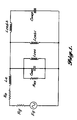
- FIG. 6 there is shown an electrical equivalent circuit diagram of the speaker system of Figures 3-5.
- the elements shown in Figure 6 follow the same convention as the circuit of Figure 1, with the addition of some new elements which correspond as follows: Rleb1 - leakage losses for wall cavity Rieb1 - internal and vibrational losses of wall cavity Rleb2 - leakage losses for ported cavity Rieb2 - internal losses of ported cavity Riep - internal losses of port
- Leakage and vibrational losses are usually negligible for commercially constructed loudspeaker enclosures but have been shown, by experiment, to be significant for most wall mounting situations.
- size and space limitations prohibit the use of a port arrangement optimized for minimum internal loss. Therefore, port internal losses play an important role in the ultimate performance of the system. Leakage loss for the ported cavity should be negligibly small while internal losses will be a controllable design parameter.
- the two transducers 17 and 18 are 6.5 inch drivers.
- the entire enclosure 16 has approximate dimensions of 12 inches wide, 18 inches high and 3 inches deep. These dimensions allow the system to be mounted in the depth of a standard two-by-four stud wall or partition without impairing performance.
- the circuit element values used above are calculated from easily realizable system parameters.
- the system may be mounted essentially flush into the wall or other partition and "painted out" leaving only a roughly 6 square inch port opening 23 as the only evidence of its presence.
- An additional advantage of the present invention is that its band-pass characteristics substantially reduce the cost and complexity of the electrical crossover network required to blend its performance with the higher frequency units.
- one variation on the system of the present invention is to use a drone cone 24 as the passive radiator output of the system.
- a drone cone radiator may be constructed with much less loss than the practical realization of the port version of the system in the preferred embodiment discussed above. This would contribute to improved efficiency at the lower frequencies reproduced by the present invention.
- An obvious disadvantage to such an arrangement, however, is that a drone cone passive radiator for this application, say on the order of 8 inches in diameter, would have a much larger surface area than that of the port opening and would be much more visually obtrusive.
- the present invention is not limited to loudspeaker systems for mounting only in wall, floor or ceiling structural partitions.
- the same principles are applicable to mounting in structural partitions in the interior of automobiles, where many of the same conditions (mainly of uncertainty) apply to situations where a consistent level of performance is required in a variety of different thru-panel mounting situations.
- the schematic drawing of Figures 3A and 3B apply where the partition 11 is a partition in an automobile with front panel 12 being an interior panel of the automobile.
- the preferred embodiment of the present invention which uses at least two transducers 17 and 18 mounted in the enclosure, offers an additional advantage. Specifically, one of the transducers can be electrically driven by one of the two stereo output channels and the other transducer driven by the other of the two stereo output channels. Such an arrangement creates a center channel sub-woofer without the need for electrically combining the two channels.
- the port opening 23 (Figs. 3A, 4, 5) will act as a transmission line at frequencies where the port length is an odd multiple of one-half wavelength. At these frequencies, energy will be transmitted from the interior of the ported cavity to the listening area with very little attenuation. Usually the frequencies at which this occurs will be far enough above the desired operating range that they can be easily attenuated with a simple low-pass network at the input to the transducers. However, when the length of the port is relatively long, the lowest transmission line frequency may be too close to the operating range to permit attenuation using a simple network.
- the solution to this problem is to provide an acoustic trap 27 to eliminate the undesirable frequencies.
- This trap may be a tube sealed at one end and opening into the side of the port at its other end, with its length being one-quarter of the wavelength of the lowest undesirable frequency.
- the trap may consist of a Helmholtz resonator 28 opening into the side of the port.
- a Helmholtz resonator as known to those skilled in the art, consists of an acoustic mass and an acoustic compliance tuned to resonate at the undesirable frequency.
- the resonator would consist of a small sealed cavity of appropriate volume connected to the side of the port by a tube containing the desired acoustic mass, as shown in Figure 11.
- the port dimensions created an unwanted transmission line frequency at approximately 500 Hz, which was removed by the use of a quarter wave trap ( Figures 8, 9 and 10) approximately 6.3 inches in length and 1.4 inches in diameter.
- the rear of the loudspeaker diaphragm must radiate into a sufficiently large volume of enclosed air. While the volume of air enclosed between the two faces or panels of a typical wall partition is usually large enough, lack of adequate rigidity in typical wall construction leads to the undesirable transmission of sound through the back or rear panel of the wall as discussed above. This problem is exacerbated when high sound pressure levels of low and mid frequencies are produced within the wall and when the spacing between the back of the sound radiating elements or electroacoustical transducers and the rear wall face behind the loudspeaker is small or restricted. Although a rigid rear enclosure or "back box" would prevent this, space restrictions encountered when making in-wall loudspeaker installations frequently make the use of back boxes of sufficient size extremely difficult or impossible.
- the sound radiating elements or electroacoustical transducers 17, 18 are spaced less than one inch from the rear panel of the partition behind the system in a typical installation.
- Figure 12 is a cross-sectional side view of a speaker system installed in a partition in accordance with an embodiment of the present invention wherein a compression plate is used to isolate the speakers from a rear panel of the partition
- Figure 13 is a pictorial view, partially broken away of the system of Figure 12.
- Like reference numerals are used in Figures 12 and 13 as in Figures 1-11 to refer to the same elements.
- a structural partition is formed of front panel 12 and rear panel 13 spaced by studs 26.
- Enclosure 16 has electroacoustical transducers or sound radiating elements 17 and 18 mounted in its wall.
- the transducers 17 and 18 have two-sided vibratory diaphragms, one side of which faces into the air space 14 of the partition or wall, and the other side of which faces into an air volume 19 defined by and substantially enclosed by the configuration of the enclosure 16.
- a passive radiating means, such as port 23 couples the specific air volume 19 within enclosure 16 to the outside listening area fronted by front panel 12.
- Figures 12 and 13 also show use of a plinth member 31 useful for mounting the enclosure 16 to the front panel 12 of the wall.
- Figures 12 and 13 show a compression plate 32 mounted to the back wall of the enclosure 16 by two side members 33 and 34 all of which are suitably fastened together as by adhesives or fasteners.
- the compression plate was spaced approximately three quarters of an inch from the sound radiating elements 17 and 18 by the side members, but this distance can obviously be increased or decreased.
- the compression plate 32 is a rigid plate formed of any suitable material and forms, with the side members 33 and 34, an enclosure in back of the sound radiating elements which is substantially sealed on the back and sides but open on the top and bottom. This forms in effect a partial enclosure.
- this partial enclosure is to isolate the portion of the rear panel 13 immediately behind the sound radiating elements, while permitting the system to continue to "see" the entire volume of air 14 within the partition or wall. Above and below the loudspeaker system this partial enclosure is entirely open to the air within the wall. In these areas the volume velocity of sound is spread over a substantially larger cross-sectional area and results in much lower sound pressure, which in turn serves to minimize excitation of the rear panel or wall surface behind the system.
- the partial enclosure due to its narrow depth dimension, does add acoustic mass to the sound radiating elements requiring that adjustments be made to the tuning of the system to maintain optimum performance. Suitable tuning adjustments, such as the volume of the enclosure 16, etc. are well within the level of those skilled in the art.
- the compression plate technique illustrated in Figures 12 and 13 can be used with virtually any in-wall loudspeaker system wherein the sound radiating elements are open to the rear partition panel, to provide isolation of that rear panel from the intense sound pressure produced in the small space behind the sound radiating elements.
- this aspect of the invention is not limited to a system and method constituting a "bandpass" sub-woofer, but is applicable to other systems and methods for in-wall loudspeaker installations as well.
- the compression plate need not be flat as shown in Figures 12 and 13, but may conform in shape to accommodate specific requirements of any system.
- the total area open to the air volume within the partition or wall may be as little as one third the total area of the sound radiating elements to be partially enclosed by the compression plate and its supports.
- the volume and dimensions of the partial enclosure are important only in that they affect the acoustic mass of the system and hence the tuning of the system.
- the partial enclosure may be open or partially open on the sides and that the compression plate itself may be partially open. Care, however, must be taken to avoid a geometry which creates a mass of air operating like a port where the primary openings of the partial enclosure join the air volume within the wall.
Applications Claiming Priority (4)
| Application Number | Priority Date | Filing Date | Title |
|---|---|---|---|
| US07/294,150 US4924963A (en) | 1989-01-05 | 1989-01-05 | Compact and efficient sub-woofer system and method for installation in structural partitions |
| US294150 | 1989-01-05 | ||
| US342042 | 1989-04-21 | ||
| US07/342,042 US4903300A (en) | 1989-01-05 | 1989-04-21 | Compact and efficient sub-woofer system and method for installation in structural partitions |
Publications (2)
| Publication Number | Publication Date |
|---|---|
| EP0377262A2 true EP0377262A2 (de) | 1990-07-11 |
| EP0377262A3 EP0377262A3 (de) | 1991-10-30 |
Family
ID=26968366
Family Applications (1)
| Application Number | Title | Priority Date | Filing Date |
|---|---|---|---|
| EP19890250128 Withdrawn EP0377262A3 (de) | 1989-01-05 | 1989-12-22 | Kompaktes und effizientes Tiefbass-Lautsprechersystem und Verfahren zum Einbau in Gehäusestrukturen |
Country Status (4)
| Country | Link |
|---|---|
| US (1) | US4903300A (de) |
| EP (1) | EP0377262A3 (de) |
| JP (1) | JPH02228194A (de) |
| CA (1) | CA2002593A1 (de) |
Cited By (4)
| Publication number | Priority date | Publication date | Assignee | Title |
|---|---|---|---|---|
| EP0429121B1 (de) * | 1989-11-16 | 1994-08-31 | Koninklijke Philips Electronics N.V. | Lautsprecheraufbau mit einem an eine akustische Röhre angeschlossenen Helmholtz-Resonator |
| EP0682853A1 (de) * | 1993-02-05 | 1995-11-22 | Thomson Consumer Electronics, Inc. | Lautsprecherbox |
| GB2310559A (en) * | 1996-02-23 | 1997-08-27 | Nokia Mobile Phones Ltd | Loudspeaker housing arrangements |
| EP1465452A2 (de) * | 2003-03-31 | 2004-10-06 | Bose Corporation | Elektroakustischer Wandler mit schmaler Öffnung |
Families Citing this family (37)
| Publication number | Priority date | Publication date | Assignee | Title |
|---|---|---|---|---|
| WO1993012637A1 (en) * | 1991-12-12 | 1993-06-24 | Blakeslee Thomas R | Changeable art loudspeaker |
| US5689573A (en) * | 1992-01-07 | 1997-11-18 | Boston Acoustics, Inc. | Frequency-dependent amplitude modification devices for acoustic sources |
| US5423500A (en) * | 1993-07-06 | 1995-06-13 | Dana Innovatins | Flat bracket for wall mount speakers |
| US6141428A (en) * | 1993-10-28 | 2000-10-31 | Narus; Chris | Audio speaker system |
| JP3118363B2 (ja) * | 1994-02-25 | 2000-12-18 | 株式会社ケンウッド | スピーカシステム |
| WO1997043852A1 (en) * | 1995-02-10 | 1997-11-20 | Samsung Electronics Co., Ltd. | Television receiver with doors for its display screen which doors contain loudspeakers |
| US6215885B1 (en) | 1997-06-26 | 2001-04-10 | George R. Geiger | Audio speaker |
| US6687380B1 (en) * | 1999-12-17 | 2004-02-03 | Broan-Nutone Llc | Active sub-woofer speaker system |
| US20060072776A1 (en) * | 1999-12-17 | 2006-04-06 | Tejaswi Vishwamitra | Amplifier and sub-woofer speaker system |
| US6307947B1 (en) | 2000-03-01 | 2001-10-23 | David Wiener | Low profile speaker enclosure |
| US6510919B1 (en) | 2000-08-30 | 2003-01-28 | Awi Licensing Company | Facing system for a flat panel radiator |
| US20030048918A1 (en) * | 2001-09-07 | 2003-03-13 | Dillon Geoffrey M. | Installing a high fidelity sound, voice paging, or music system by mounting an electrical to acoustic transducer inside a wall mounted gang box |
| US20030123679A1 (en) * | 2002-01-02 | 2003-07-03 | Dudleston William R. | In-wall loudspeaker |
| US20040019569A1 (en) * | 2002-07-25 | 2004-01-29 | Yun-Chi Lee | Online real-time information inquiry method and system for importing commodities |
| US6985593B2 (en) * | 2002-08-23 | 2006-01-10 | Bose Corporation | Baffle vibration reducing |
| US7551749B2 (en) * | 2002-08-23 | 2009-06-23 | Bose Corporation | Baffle vibration reducing |
| US7292702B2 (en) | 2003-04-29 | 2007-11-06 | Dimensional Communications, Inc. | In-wall speaker system method and apparatus |
| US20080085029A1 (en) * | 2003-04-29 | 2008-04-10 | Hagman Paul N | In-wall speaker system method and apparatus |
| US7463744B2 (en) * | 2003-10-31 | 2008-12-09 | Bose Corporation | Porting |
| US7584820B2 (en) * | 2004-03-19 | 2009-09-08 | Bose Corporation | Acoustic radiating |
| US7565948B2 (en) * | 2004-03-19 | 2009-07-28 | Bose Corporation | Acoustic waveguiding |
| JP4230421B2 (ja) * | 2004-07-09 | 2009-02-25 | パイオニア株式会社 | スピーカ装置 |
| BRPI0500805A (pt) * | 2005-03-10 | 2006-10-31 | Gradiente Eletronica S A | caixa acústica |
| US7353907B2 (en) * | 2005-08-16 | 2008-04-08 | Whitaker Scott R | Speaker enclosure for a wall mounted speaker system |
| US7503422B2 (en) * | 2005-12-08 | 2009-03-17 | Induction Dynamics Llc | Expandable speaker enclosure |
| US7530425B2 (en) * | 2006-06-08 | 2009-05-12 | Whitaker Scott R | Speaker enclosure for a ceiling or wall mounted speaker method and apparatus |
| US7963076B2 (en) * | 2006-09-11 | 2011-06-21 | Dana Innovations | Devices and methods for flangeless installations |
| US8180076B2 (en) * | 2008-07-31 | 2012-05-15 | Bose Corporation | System and method for reducing baffle vibration |
| US20100050537A1 (en) * | 2008-09-04 | 2010-03-04 | Jim Lee Murray | Universal back box for mounting in wall components and method of use |
| US8605936B2 (en) | 2010-09-16 | 2013-12-10 | Jl Audio, Inc. | In-wall loudspeaker mounting method and apparatus |
| US8611575B1 (en) | 2010-11-04 | 2013-12-17 | Paul N. Hagman | Speaker system method and apparatus |
| CN102340713A (zh) * | 2011-07-25 | 2012-02-01 | 李世煌 | 平板设备的外设音箱 |
| US8958591B2 (en) | 2011-12-20 | 2015-02-17 | Paul N. Hagman | Speaker system method and apparatus |
| JP6446022B2 (ja) | 2013-03-13 | 2018-12-26 | ティ エイチ エックス リミテッド | 薄型スピーカ |
| US9525932B2 (en) * | 2015-01-26 | 2016-12-20 | Bose Corporation | Acoustic device having active drivers mounted to a passive radiator diaphragm |
| US9716941B2 (en) * | 2015-07-06 | 2017-07-25 | GM Global Technology Operations LLC | Frame rail-integrated subwoofer assembly and method |
| US10587949B1 (en) | 2018-03-28 | 2020-03-10 | Paul N. Hagman | Acoustically tuned face panel for speaker system |
Citations (4)
| Publication number | Priority date | Publication date | Assignee | Title |
|---|---|---|---|---|
| US2646852A (en) * | 1949-04-21 | 1953-07-28 | Forrester John | Loud-speaker cabinet |
| US4139075A (en) * | 1976-08-31 | 1979-02-13 | Sansui Electric Co., Ltd. | Loudspeaker device |
| US4296280A (en) * | 1980-03-17 | 1981-10-20 | Richie Ronald A | Wall mounted speaker system |
| FR2613167A3 (fr) * | 1987-03-27 | 1988-09-30 | Fouquet Claude | Charge de grave permettant l'augmentation du rendement dans un faible volume |
Family Cites Families (5)
| Publication number | Priority date | Publication date | Assignee | Title |
|---|---|---|---|---|
| US3067834A (en) * | 1961-03-13 | 1962-12-11 | Oscar R May | Speaker unit for drive-in theater |
| US3848090A (en) * | 1971-11-18 | 1974-11-12 | J Walker | Wall hanging speaker system |
| US4146744A (en) * | 1976-09-02 | 1979-03-27 | Bose Corporation | Low q multiple in phase high compliance driver ported loudspeaker enclosure |
| SE418665B (sv) * | 1979-10-16 | 1981-06-15 | Gustav Georg Arne Bolin | Sett att forbettra akustiken i en lokal |
| US4778027A (en) * | 1987-04-30 | 1988-10-18 | Taylor Mildred E | Rhythmizer |
-
1989
- 1989-04-21 US US07/342,042 patent/US4903300A/en not_active Expired - Fee Related
- 1989-11-09 CA CA002002593A patent/CA2002593A1/en not_active Abandoned
- 1989-12-22 EP EP19890250128 patent/EP0377262A3/de not_active Withdrawn
-
1990
- 1990-01-05 JP JP2000911A patent/JPH02228194A/ja active Pending
Patent Citations (4)
| Publication number | Priority date | Publication date | Assignee | Title |
|---|---|---|---|---|
| US2646852A (en) * | 1949-04-21 | 1953-07-28 | Forrester John | Loud-speaker cabinet |
| US4139075A (en) * | 1976-08-31 | 1979-02-13 | Sansui Electric Co., Ltd. | Loudspeaker device |
| US4296280A (en) * | 1980-03-17 | 1981-10-20 | Richie Ronald A | Wall mounted speaker system |
| FR2613167A3 (fr) * | 1987-03-27 | 1988-09-30 | Fouquet Claude | Charge de grave permettant l'augmentation du rendement dans un faible volume |
Cited By (8)
| Publication number | Priority date | Publication date | Assignee | Title |
|---|---|---|---|---|
| EP0429121B1 (de) * | 1989-11-16 | 1994-08-31 | Koninklijke Philips Electronics N.V. | Lautsprecheraufbau mit einem an eine akustische Röhre angeschlossenen Helmholtz-Resonator |
| EP0682853A1 (de) * | 1993-02-05 | 1995-11-22 | Thomson Consumer Electronics, Inc. | Lautsprecherbox |
| EP0682853A4 (de) * | 1993-02-05 | 1996-01-10 | Thomson Consumer Electronics | Lautsprecherbox. |
| GB2310559A (en) * | 1996-02-23 | 1997-08-27 | Nokia Mobile Phones Ltd | Loudspeaker housing arrangements |
| GB2310559B (en) * | 1996-02-23 | 2000-09-20 | Nokia Mobile Phones Ltd | Audio output apparatus for a mobile communication device |
| EP1465452A2 (de) * | 2003-03-31 | 2004-10-06 | Bose Corporation | Elektroakustischer Wandler mit schmaler Öffnung |
| EP1465452A3 (de) * | 2003-03-31 | 2005-09-21 | Bose Corporation | Elektroakustischer Wandler mit schmaler Öffnung |
| US7463746B2 (en) | 2003-03-31 | 2008-12-09 | Bose Corporation | Narrow opening electroacoustical transducing |
Also Published As
| Publication number | Publication date |
|---|---|
| EP0377262A3 (de) | 1991-10-30 |
| US4903300A (en) | 1990-02-20 |
| CA2002593A1 (en) | 1990-07-05 |
| JPH02228194A (ja) | 1990-09-11 |
Similar Documents
| Publication | Publication Date | Title |
|---|---|---|
| US4903300A (en) | Compact and efficient sub-woofer system and method for installation in structural partitions | |
| US5471019A (en) | Multiple chamber loudspeaker system | |
| US4924963A (en) | Compact and efficient sub-woofer system and method for installation in structural partitions | |
| US6389146B1 (en) | Acoustically asymmetric bandpass loudspeaker with multiple acoustic filters | |
| US4031318A (en) | High fidelity loudspeaker system | |
| US4953655A (en) | Acoustic apparatus | |
| US5875255A (en) | High power electroacoustic speaker system having wide band frequency response | |
| EP0778720B1 (de) | Tieftonlautsprecher | |
| US5815589A (en) | Push-pull transmission line loudspeaker | |
| US20020061114A1 (en) | Bandpass woofer enclosure with multiple acoustic filters | |
| US5374124A (en) | Multi-compound isobarik loudspeaker system | |
| US7298862B2 (en) | Asymmetrical loudspeaker enclosures with enhanced low frequency response | |
| US5657392A (en) | Multi-way speaker with a cabinet defining a midrange driver pyramidal compartment | |
| WO1999035883A1 (en) | Thin loudspeaker | |
| US20070003076A1 (en) | Bandpass woofer enclosure with multiple acoustic filters | |
| WO1991008657A1 (en) | Speaker enclosure | |
| WO2005029916A1 (en) | Loudspeaker enclosure | |
| US3473625A (en) | Sound reproduction system and loudspeaker assembly | |
| JPH0628876Y2 (ja) | 低音域再生用スピーカシステム | |
| US5033577A (en) | Room sound reproducing | |
| Klipsch | A low frequency horn of small dimensions | |
| JP2003299168A (ja) | スピーカシステム | |
| JPH01218298A (ja) | ステレオ型スピーカ装置 | |
| JPH02202298A (ja) | 多重共鳴型スピーカシステム | |
| JP3470582B2 (ja) | スピーカ |
Legal Events
| Date | Code | Title | Description |
|---|---|---|---|
| PUAI | Public reference made under article 153(3) epc to a published international application that has entered the european phase |
Free format text: ORIGINAL CODE: 0009012 |
|
| AK | Designated contracting states |
Kind code of ref document: A2 Designated state(s): AT BE CH DE ES FR GB GR IT LI LU NL SE |
|
| PUAL | Search report despatched |
Free format text: ORIGINAL CODE: 0009013 |
|
| AK | Designated contracting states |
Kind code of ref document: A3 Designated state(s): AT BE CH DE ES FR GB GR IT LI LU NL SE |
|
| 17P | Request for examination filed |
Effective date: 19920404 |
|
| STAA | Information on the status of an ep patent application or granted ep patent |
Free format text: STATUS: THE APPLICATION IS DEEMED TO BE WITHDRAWN |
|
| 18D | Application deemed to be withdrawn |
Effective date: 19930701 |