EP0376995B1 - Beschleunigungsaufnehmer - Google Patents
Beschleunigungsaufnehmer Download PDFInfo
- Publication number
- EP0376995B1 EP0376995B1 EP89904774A EP89904774A EP0376995B1 EP 0376995 B1 EP0376995 B1 EP 0376995B1 EP 89904774 A EP89904774 A EP 89904774A EP 89904774 A EP89904774 A EP 89904774A EP 0376995 B1 EP0376995 B1 EP 0376995B1
- Authority
- EP
- European Patent Office
- Prior art keywords
- flexural
- resistors
- sensor according
- flexural spring
- spring
- Prior art date
- Legal status (The legal status is an assumption and is not a legal conclusion. Google has not performed a legal analysis and makes no representation as to the accuracy of the status listed.)
- Expired - Lifetime
Links
- 230000001133 acceleration Effects 0.000 title claims abstract description 12
- 238000011156 evaluation Methods 0.000 claims abstract description 13
- 238000005516 engineering process Methods 0.000 claims abstract description 11
- 229910010293 ceramic material Inorganic materials 0.000 claims description 3
- 239000000463 material Substances 0.000 abstract description 3
- 238000004519 manufacturing process Methods 0.000 abstract description 2
- PNEYBMLMFCGWSK-UHFFFAOYSA-N aluminium oxide Inorganic materials [O-2].[O-2].[O-2].[Al+3].[Al+3] PNEYBMLMFCGWSK-UHFFFAOYSA-N 0.000 abstract 1
- 229910052593 corundum Inorganic materials 0.000 abstract 1
- 229910001845 yogo sapphire Inorganic materials 0.000 abstract 1
- 238000005452 bending Methods 0.000 description 8
- 239000010408 film Substances 0.000 description 4
- 239000000919 ceramic Substances 0.000 description 2
- 238000005259 measurement Methods 0.000 description 2
- TWNQGVIAIRXVLR-UHFFFAOYSA-N oxo(oxoalumanyloxy)alumane Chemical compound O=[Al]O[Al]=O TWNQGVIAIRXVLR-UHFFFAOYSA-N 0.000 description 2
- 239000000758 substrate Substances 0.000 description 2
- 238000011161 development Methods 0.000 description 1
- 230000018109 developmental process Effects 0.000 description 1
- 238000012986 modification Methods 0.000 description 1
- 230000004048 modification Effects 0.000 description 1
- 230000003014 reinforcing effect Effects 0.000 description 1
- 239000004065 semiconductor Substances 0.000 description 1
- 230000035945 sensitivity Effects 0.000 description 1
- 239000000725 suspension Substances 0.000 description 1
- 239000010409 thin film Substances 0.000 description 1
Images

Classifications
-
- G—PHYSICS
- G01—MEASURING; TESTING
- G01P—MEASURING LINEAR OR ANGULAR SPEED, ACCELERATION, DECELERATION, OR SHOCK; INDICATING PRESENCE, ABSENCE, OR DIRECTION, OF MOVEMENT
- G01P15/00—Measuring acceleration; Measuring deceleration; Measuring shock, i.e. sudden change of acceleration
- G01P15/02—Measuring acceleration; Measuring deceleration; Measuring shock, i.e. sudden change of acceleration by making use of inertia forces using solid seismic masses
- G01P15/08—Measuring acceleration; Measuring deceleration; Measuring shock, i.e. sudden change of acceleration by making use of inertia forces using solid seismic masses with conversion into electric or magnetic values
- G01P15/12—Measuring acceleration; Measuring deceleration; Measuring shock, i.e. sudden change of acceleration by making use of inertia forces using solid seismic masses with conversion into electric or magnetic values by alteration of electrical resistance
- G01P15/123—Measuring acceleration; Measuring deceleration; Measuring shock, i.e. sudden change of acceleration by making use of inertia forces using solid seismic masses with conversion into electric or magnetic values by alteration of electrical resistance by piezo-resistive elements, e.g. semiconductor strain gauges
Definitions
- the invention is based on an accelerometer according to the preamble of the main claim. It is known to clamp the spiral spring on one side over the entire width in the case of acceleration sensors and to determine the deflection of the spiral spring with the aid of piezoresistive elements. These transducers are relatively highly cross-sensitive and have no warning device in the event of breakage or other damage to the spiral spring.
- an acceleration sensor is known, the rigid beam serving as seismic mass is fastened on one side to a carrier with the aid of two parts arranged in a coplanar manner and a flexible part oriented perpendicularly to these.
- a strain gauge for generating measurement signals is arranged on each of the three flexible parts. With the aid of this arrangement, it should be possible to detect the acceleration in all three directions and in particular also to detect the torsion in the area of the flexible parts. With the help of this device, both the size and the direction of the accelerations acting can be determined, but there are no indications of torsion-free measurement signal acquisition.
- the spiral spring is clamped with one end directly in a housing.
- the spiral spring there are resistors for measuring signal acquisition and at the same time the evaluation circuit.
- the seismic mass is arranged at the other the free end of the spiral spring.
- the sensor according to FR-A-2 438 829 has a spiral spring which is in turn clamped directly on one side in a housing. On the top and bottom of this spiral spring, several resistors for measuring signal acquisition are applied in the area of the clamping point. However, this sensor has no torsion protection.
- the accelerometer according to the invention with the characterizing features of the main claim has the advantage that it determines the acceleration particularly easily, accurately and safely.
- the cross sensitivity of the spiral spring to acceleration in the plane of the spiral spring is reduced.
- transverse signals caused by torsion of the spiral spring are suppressed by the suspension.
- the spiral spring is therefore only sensitive to bending.
- the special arrangement of the resistances of the Wheatstone bridge circuit means that the mechanical range of the transducer, ie its spiral spring, can be checked at any time possible.
- the electrical closed circuit of the Wheatstone bridge is interrupted by mechanical damage to the bridge. This enables electrical control of the mechanical state of the transducer even in the installed state. Due to the special arrangement of the resistors according to claim 4, the vibrating seismic mass can also be included in the electrical control.
- the evaluation circuit can be arranged on an extension of the spiral spring.
- the evaluation circuit can be applied to a ceramic substrate in a high-strength area using hybrid technology. No interference signals are generated in the evaluation circuit by mechanical deformation in this area.
- the spiral spring can thus be made relatively thin and sensitive.
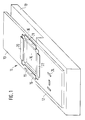
- FIG. 1 shows a perspective illustration of a sensor
- FIG. 2 shows a modification according to FIG. 1.
- 10 denotes the step-like mounting of an accelerometer 11, which can be made of any, but relatively rigid material.
- a seismic spiral spring 13 made of ceramic material, such as aluminum oxide (Al2O3).
- the spiral spring 13 has a cutout 14 in the area of the step on, so that this creates two parallel bending webs 15, 16 with which the spiral spring is elastically fastened to the elevation 12 of the holder 10.
- the recess 14 is formed so long that the bending webs 15, 16 are as far apart as possible, in particular the outer edges of the bending webs 15, 16 can be flush with the outer edges of the spiral spring 13.
- the four strain-sensitive sensor resistors 19 to 22 of a Wheatstone bridge circuit are arranged on the spiral spring 13.
- the opposing resistors 19, 21 are each applied to one of the bending webs 15, 16.
- the remaining resistors 20 and 22 are located on the oscillating area of the spiral spring 13 in the region of the recess 14 and in the region of the recess 14 on the spiral spring 13 in the region of the elevation 12.
- the resistors 19 to 22 are in thick-film technology on the spiral spring 13 applied, and work on the piezoresistive principle.
- an evaluation circuit 24 in hybrid technology. It has active, e.g. reinforcing members (semiconductors), and passive e.g. R, C components.
- the evaluation circuit 24 is also constructed using thick-film technology.
- Control unit which controls the occupant protection devices of the motor vehicle, e.g. Belt tensioners or airbags can trigger.
- the mechanical state of the spiral spring 13 can be electrically controlled with the aid of the Wheatstone bridge circuit. If the bending webs 15, 16 are damaged, for example one of them breaks, the electrical closed circuit of the Wheatstone bridge circuit becomes interrupted. In the embodiment according to FIG. 1, the electrical lines between the resistors 19 to 22 of the bridge circuit are minimized. As shown in FIG. 2, the resistor 20a can also be arranged on the end of the spiral spring 13 facing away from the elevation 12. This makes it possible to monitor the mechanical functionality of the entire spiral spring, since the lines are guided over the entire circumference of the spiral spring 13.
- an accelerometer 11 is sufficiently known and is therefore not described in detail here. If the spiral spring 13 is deflected from its rest position, the spiral spring 13 is in the region of the bending webs 15, 16, i.e. bent in the area of the resistors 19, 21 and produced a proportional change in resistance in these. This change in resistance is evaluated in the evaluation circuit 24 and forwarded to the control unit.
- the evaluation circuit 24 can be applied in a single operation using thick-film technology. The manufacturing effort is minimized. Furthermore, due to the rigid material of the holder 10, the evaluation circuit 24 can be applied in an area almost free of mechanical bending stresses. Interference signals in the evaluation circuit 24 can thereby be avoided.
Landscapes
- Physics & Mathematics (AREA)
- General Physics & Mathematics (AREA)
- Pressure Sensors (AREA)
- Measurement Of Mechanical Vibrations Or Ultrasonic Waves (AREA)
- Air Bags (AREA)
Applications Claiming Priority (2)
| Application Number | Priority Date | Filing Date | Title |
|---|---|---|---|
| DE3814949 | 1988-05-03 | ||
| DE3814949A DE3814949C1 (enExample) | 1988-05-03 | 1988-05-03 |
Publications (2)
| Publication Number | Publication Date |
|---|---|
| EP0376995A1 EP0376995A1 (de) | 1990-07-11 |
| EP0376995B1 true EP0376995B1 (de) | 1992-07-15 |
Family
ID=6353456
Family Applications (1)
| Application Number | Title | Priority Date | Filing Date |
|---|---|---|---|
| EP89904774A Expired - Lifetime EP0376995B1 (de) | 1988-05-03 | 1989-04-25 | Beschleunigungsaufnehmer |
Country Status (5)
| Country | Link |
|---|---|
| US (1) | US5107708A (enExample) |
| EP (1) | EP0376995B1 (enExample) |
| JP (1) | JPH02504078A (enExample) |
| DE (2) | DE3814949C1 (enExample) |
| WO (1) | WO1989011104A1 (enExample) |
Families Citing this family (9)
| Publication number | Priority date | Publication date | Assignee | Title |
|---|---|---|---|---|
| US5456109A (en) * | 1993-03-29 | 1995-10-10 | Delco Electronics Corporation | Thick film rotational accelerometer having two structurally integrated linear acceleration sensors |
| JPH0761320A (ja) * | 1993-08-24 | 1995-03-07 | Nippon Seiko Kk | 衝撃検知装置 |
| US5524490A (en) * | 1994-05-25 | 1996-06-11 | Delco Electronics Corporation | Inductive proximity sensor |
| DE4419902A1 (de) * | 1994-06-07 | 1995-12-14 | Siemens Ag | Beschleunigungssensor |
| WO1997030356A1 (en) * | 1996-02-15 | 1997-08-21 | Honeywell Inc. | Apparatus for detection of proof mass rupture in an accelerometer |
| US5798641A (en) * | 1997-03-17 | 1998-08-25 | Quantum Design, Inc. | Torque magnetometer utilizing integrated piezoresistive levers |
| DE19814261A1 (de) * | 1998-03-31 | 1999-10-14 | Mannesmann Vdo Ag | Dehnungsempfindlicher Widerstand |
| DE10036495C2 (de) * | 2000-07-25 | 2003-07-03 | Elektronik Sachsen Gmbh Ab | Kraftmessvorrichtung in Form eines Biegebalkensensors |
| WO2011161917A1 (ja) * | 2010-06-25 | 2011-12-29 | パナソニック株式会社 | 加速度センサ |
Family Cites Families (7)
| Publication number | Priority date | Publication date | Assignee | Title |
|---|---|---|---|---|
| US4311980A (en) * | 1978-10-12 | 1982-01-19 | Fabrica Italiana Magneti Marelli, S.P.A. | Device for pressure measurement using a resistor strain gauge |
| US4488445A (en) * | 1983-10-28 | 1984-12-18 | Honeywell Inc. | Integrated silicon accelerometer with cross-axis compensation |
| GB2174500B (en) * | 1985-05-04 | 1988-02-10 | Stc Plc | Accelerometer |
| DE8607653U1 (de) * | 1986-03-20 | 1987-08-06 | Robert Bosch Gmbh, 7000 Stuttgart | Beschleunigungsaufnehmer |
| DE3705846A1 (de) * | 1986-03-20 | 1987-09-24 | Mittweida Ing Hochschule | Automatisches sicherheitsgurt-notloesesystem |
| FR2604791B1 (fr) * | 1986-10-02 | 1988-11-25 | Commissariat Energie Atomique | Procedes de fabrication d'une jauge piezoresistive et d'un accelerometre comportant une telle jauge |
| DE3814952A1 (de) * | 1988-05-03 | 1989-11-23 | Bosch Gmbh Robert | Sensor |
-
1988
- 1988-05-03 DE DE3814949A patent/DE3814949C1/de not_active Expired
-
1989
- 1989-04-25 EP EP89904774A patent/EP0376995B1/de not_active Expired - Lifetime
- 1989-04-25 WO PCT/DE1989/000263 patent/WO1989011104A1/de not_active Ceased
- 1989-04-25 DE DE8989904774T patent/DE58901847D1/de not_active Expired - Lifetime
- 1989-04-25 JP JP1504441A patent/JPH02504078A/ja active Pending
- 1989-04-25 US US07/457,762 patent/US5107708A/en not_active Expired - Fee Related
Also Published As
| Publication number | Publication date |
|---|---|
| US5107708A (en) | 1992-04-28 |
| DE58901847D1 (de) | 1992-08-20 |
| DE3814949C1 (enExample) | 1989-08-03 |
| WO1989011104A1 (fr) | 1989-11-16 |
| JPH02504078A (ja) | 1990-11-22 |
| EP0376995A1 (de) | 1990-07-11 |
Similar Documents
| Publication | Publication Date | Title |
|---|---|---|
| EP0244581B1 (de) | Sensor zur selbsttätigen Auslösung von Insassenschutzvorrichtungen | |
| DE69432396T2 (de) | Beschleunigungsmessaufnehmer | |
| DE69206758T2 (de) | Beschleunigungsmessanordnung mit Auswerteschaltung | |
| DE68910641T2 (de) | Selbsteichender Beschleunigungsmesser. | |
| EP0394305B1 (de) | Vorrichtung zur messung von beschleunigungen | |
| EP1979709B1 (de) | Inertialsensoranordnung | |
| DE4316279A1 (de) | Halbleiter-Beschleunigungsmesser | |
| EP0790483B1 (de) | Neigungssensor | |
| EP0376995B1 (de) | Beschleunigungsaufnehmer | |
| DE10225714A1 (de) | Mehrachsiger monolithischer Beschleunigungssensor | |
| DE3814952A1 (de) | Sensor | |
| EP0261153B1 (de) | Beschleunigungsaufnehmer | |
| DE69328381T2 (de) | Vorrichtung zur messung von kraftkomponenten in monokristallinem material, methode zur herstellung einer solchen vorrichtung sowie deren anwendung | |
| DE3814950A1 (de) | Beschleunigungsaufnehmer | |
| DE19620459A1 (de) | Halbleiter-Beschleunigungsmesser und Verfahren zur Bewertung der Eigenschaften eines Halbleiter-Beschleunigungsmessers | |
| DE3917611C2 (enExample) | ||
| DE3824695A1 (de) | Mikromechanischer beschleunigungssensor mit kapazitiver signalwandlung und verfahren zu seiner herstellung | |
| DE69611328T2 (de) | Aufprallsensor | |
| DE69528572T2 (de) | Messwertaufnehmer für Beschleunigungszustand | |
| DE4340664C2 (de) | Piezoresistiver Beschleunigungsaufnehmer | |
| DE19752439C2 (de) | Mikromechanischer Neigungssensor, insbesondere für Kraftfahrzeuge | |
| DE3742673A1 (de) | Mikro-spannungssensor | |
| DE4404265A1 (de) | Verfahren zum Kalibrieren eines Beschleunigungssensors, der insbesondere zur Steuerung eines Kfz-Airbag dient | |
| DE4033885A1 (de) | Beschleunigungssensor | |
| DE10101352B4 (de) | Neigungssensoranordnung |
Legal Events
| Date | Code | Title | Description |
|---|---|---|---|
| PUAI | Public reference made under article 153(3) epc to a published international application that has entered the european phase |
Free format text: ORIGINAL CODE: 0009012 |
|
| 17P | Request for examination filed |
Effective date: 19891130 |
|
| AK | Designated contracting states |
Kind code of ref document: A1 Designated state(s): DE FR GB IT |
|
| 17Q | First examination report despatched |
Effective date: 19910426 |
|
| RAP3 | Party data changed (applicant data changed or rights of an application transferred) |
Owner name: ROBERT BOSCH GMBH |
|
| GRAA | (expected) grant |
Free format text: ORIGINAL CODE: 0009210 |
|
| AK | Designated contracting states |
Kind code of ref document: B1 Designated state(s): DE FR GB IT |
|
| GBT | Gb: translation of ep patent filed (gb section 77(6)(a)/1977) | ||
| REF | Corresponds to: |
Ref document number: 58901847 Country of ref document: DE Date of ref document: 19920820 |
|
| ET | Fr: translation filed | ||
| ITF | It: translation for a ep patent filed | ||
| PGFP | Annual fee paid to national office [announced via postgrant information from national office to epo] |
Ref country code: GB Payment date: 19930419 Year of fee payment: 5 |
|
| PGFP | Annual fee paid to national office [announced via postgrant information from national office to epo] |
Ref country code: FR Payment date: 19930429 Year of fee payment: 5 |
|
| PLBE | No opposition filed within time limit |
Free format text: ORIGINAL CODE: 0009261 |
|
| STAA | Information on the status of an ep patent application or granted ep patent |
Free format text: STATUS: NO OPPOSITION FILED WITHIN TIME LIMIT |
|
| PGFP | Annual fee paid to national office [announced via postgrant information from national office to epo] |
Ref country code: DE Payment date: 19930624 Year of fee payment: 5 |
|
| 26N | No opposition filed | ||
| PG25 | Lapsed in a contracting state [announced via postgrant information from national office to epo] |
Ref country code: GB Effective date: 19940425 |
|
| GBPC | Gb: european patent ceased through non-payment of renewal fee |
Effective date: 19940425 |
|
| PG25 | Lapsed in a contracting state [announced via postgrant information from national office to epo] |
Ref country code: FR Effective date: 19941229 |
|
| PG25 | Lapsed in a contracting state [announced via postgrant information from national office to epo] |
Ref country code: DE Effective date: 19950103 |
|
| REG | Reference to a national code |
Ref country code: FR Ref legal event code: ST |
|
| PG25 | Lapsed in a contracting state [announced via postgrant information from national office to epo] |
Ref country code: IT Free format text: LAPSE BECAUSE OF NON-PAYMENT OF DUE FEES;WARNING: LAPSES OF ITALIAN PATENTS WITH EFFECTIVE DATE BEFORE 2007 MAY HAVE OCCURRED AT ANY TIME BEFORE 2007. THE CORRECT EFFECTIVE DATE MAY BE DIFFERENT FROM THE ONE RECORDED. Effective date: 20050425 |