EP0376995B1 - Acceleration sensor - Google Patents
Acceleration sensor Download PDFInfo
- Publication number
- EP0376995B1 EP0376995B1 EP89904774A EP89904774A EP0376995B1 EP 0376995 B1 EP0376995 B1 EP 0376995B1 EP 89904774 A EP89904774 A EP 89904774A EP 89904774 A EP89904774 A EP 89904774A EP 0376995 B1 EP0376995 B1 EP 0376995B1
- Authority
- EP
- European Patent Office
- Prior art keywords
- flexural
- resistors
- sensor according
- flexural spring
- spring
- Prior art date
- Legal status (The legal status is an assumption and is not a legal conclusion. Google has not performed a legal analysis and makes no representation as to the accuracy of the status listed.)
- Expired - Lifetime
Links
Images

Classifications
-
- G—PHYSICS
- G01—MEASURING; TESTING
- G01P—MEASURING LINEAR OR ANGULAR SPEED, ACCELERATION, DECELERATION, OR SHOCK; INDICATING PRESENCE, ABSENCE, OR DIRECTION, OF MOVEMENT
- G01P15/00—Measuring acceleration; Measuring deceleration; Measuring shock, i.e. sudden change of acceleration
- G01P15/02—Measuring acceleration; Measuring deceleration; Measuring shock, i.e. sudden change of acceleration by making use of inertia forces using solid seismic masses
- G01P15/08—Measuring acceleration; Measuring deceleration; Measuring shock, i.e. sudden change of acceleration by making use of inertia forces using solid seismic masses with conversion into electric or magnetic values
- G01P15/12—Measuring acceleration; Measuring deceleration; Measuring shock, i.e. sudden change of acceleration by making use of inertia forces using solid seismic masses with conversion into electric or magnetic values by alteration of electrical resistance
- G01P15/123—Measuring acceleration; Measuring deceleration; Measuring shock, i.e. sudden change of acceleration by making use of inertia forces using solid seismic masses with conversion into electric or magnetic values by alteration of electrical resistance by piezo-resistive elements, e.g. semiconductor strain gauges
Definitions
- the invention is based on an accelerometer according to the preamble of the main claim. It is known to clamp the spiral spring on one side over the entire width in the case of acceleration sensors and to determine the deflection of the spiral spring with the aid of piezoresistive elements. These transducers are relatively highly cross-sensitive and have no warning device in the event of breakage or other damage to the spiral spring.
- an acceleration sensor is known, the rigid beam serving as seismic mass is fastened on one side to a carrier with the aid of two parts arranged in a coplanar manner and a flexible part oriented perpendicularly to these.
- a strain gauge for generating measurement signals is arranged on each of the three flexible parts. With the aid of this arrangement, it should be possible to detect the acceleration in all three directions and in particular also to detect the torsion in the area of the flexible parts. With the help of this device, both the size and the direction of the accelerations acting can be determined, but there are no indications of torsion-free measurement signal acquisition.
- the spiral spring is clamped with one end directly in a housing.
- the spiral spring there are resistors for measuring signal acquisition and at the same time the evaluation circuit.
- the seismic mass is arranged at the other the free end of the spiral spring.
- the sensor according to FR-A-2 438 829 has a spiral spring which is in turn clamped directly on one side in a housing. On the top and bottom of this spiral spring, several resistors for measuring signal acquisition are applied in the area of the clamping point. However, this sensor has no torsion protection.
- the accelerometer according to the invention with the characterizing features of the main claim has the advantage that it determines the acceleration particularly easily, accurately and safely.
- the cross sensitivity of the spiral spring to acceleration in the plane of the spiral spring is reduced.
- transverse signals caused by torsion of the spiral spring are suppressed by the suspension.
- the spiral spring is therefore only sensitive to bending.
- the special arrangement of the resistances of the Wheatstone bridge circuit means that the mechanical range of the transducer, ie its spiral spring, can be checked at any time possible.
- the electrical closed circuit of the Wheatstone bridge is interrupted by mechanical damage to the bridge. This enables electrical control of the mechanical state of the transducer even in the installed state. Due to the special arrangement of the resistors according to claim 4, the vibrating seismic mass can also be included in the electrical control.
- the evaluation circuit can be arranged on an extension of the spiral spring.
- the evaluation circuit can be applied to a ceramic substrate in a high-strength area using hybrid technology. No interference signals are generated in the evaluation circuit by mechanical deformation in this area.
- the spiral spring can thus be made relatively thin and sensitive.
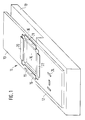
- FIG. 1 shows a perspective illustration of a sensor
- FIG. 2 shows a modification according to FIG. 1.
- 10 denotes the step-like mounting of an accelerometer 11, which can be made of any, but relatively rigid material.
- a seismic spiral spring 13 made of ceramic material, such as aluminum oxide (Al2O3).
- the spiral spring 13 has a cutout 14 in the area of the step on, so that this creates two parallel bending webs 15, 16 with which the spiral spring is elastically fastened to the elevation 12 of the holder 10.
- the recess 14 is formed so long that the bending webs 15, 16 are as far apart as possible, in particular the outer edges of the bending webs 15, 16 can be flush with the outer edges of the spiral spring 13.
- the four strain-sensitive sensor resistors 19 to 22 of a Wheatstone bridge circuit are arranged on the spiral spring 13.
- the opposing resistors 19, 21 are each applied to one of the bending webs 15, 16.
- the remaining resistors 20 and 22 are located on the oscillating area of the spiral spring 13 in the region of the recess 14 and in the region of the recess 14 on the spiral spring 13 in the region of the elevation 12.
- the resistors 19 to 22 are in thick-film technology on the spiral spring 13 applied, and work on the piezoresistive principle.
- an evaluation circuit 24 in hybrid technology. It has active, e.g. reinforcing members (semiconductors), and passive e.g. R, C components.
- the evaluation circuit 24 is also constructed using thick-film technology.
- Control unit which controls the occupant protection devices of the motor vehicle, e.g. Belt tensioners or airbags can trigger.
- the mechanical state of the spiral spring 13 can be electrically controlled with the aid of the Wheatstone bridge circuit. If the bending webs 15, 16 are damaged, for example one of them breaks, the electrical closed circuit of the Wheatstone bridge circuit becomes interrupted. In the embodiment according to FIG. 1, the electrical lines between the resistors 19 to 22 of the bridge circuit are minimized. As shown in FIG. 2, the resistor 20a can also be arranged on the end of the spiral spring 13 facing away from the elevation 12. This makes it possible to monitor the mechanical functionality of the entire spiral spring, since the lines are guided over the entire circumference of the spiral spring 13.
- an accelerometer 11 is sufficiently known and is therefore not described in detail here. If the spiral spring 13 is deflected from its rest position, the spiral spring 13 is in the region of the bending webs 15, 16, i.e. bent in the area of the resistors 19, 21 and produced a proportional change in resistance in these. This change in resistance is evaluated in the evaluation circuit 24 and forwarded to the control unit.
- the evaluation circuit 24 can be applied in a single operation using thick-film technology. The manufacturing effort is minimized. Furthermore, due to the rigid material of the holder 10, the evaluation circuit 24 can be applied in an area almost free of mechanical bending stresses. Interference signals in the evaluation circuit 24 can thereby be avoided.
Abstract
Description
Die Erfindung geht aus von einem Beschleunigungsaufnehmer nach der Gattung des Hauptanspruchs. Es ist bekannt, bei Beschleunigungsaufnehmern die Biegefeder über die gesamte Breite einseitig einzuspannen und mit Hilfe von piezoresistiven Elementen die Durchbiegung der Biegefeder zu bestimmen. Diese Aufnehmer sind relativ stark querempfindlich und weisen keine Warneinrichtung bei Bruch oder sonstiger Beschädigung der Biegefeder auf.The invention is based on an accelerometer according to the preamble of the main claim. It is known to clamp the spiral spring on one side over the entire width in the case of acceleration sensors and to determine the deflection of the spiral spring with the aid of piezoresistive elements. These transducers are relatively highly cross-sensitive and have no warning device in the event of breakage or other damage to the spiral spring.
Aus der Schrift GB-A-2 174 500 ist ein Beschleunigungssensor bekannt, dessen starrer, als seismische Masse dienender Balken mit Hilfe zweier komplanar angeordneter Teile und einem senkrecht zu diesen ausgerichteten flexiblen Teil einseitig an einem Träger befestigt ist. Auf jedem der drei flexiblen Teile ist ein Dehnmeßstreifen zur Erzeugung von Meßsignalen angeordnet. Mit Hilfe dieser Anordnung soll eine Erfassung der Beschleunigung in allen drei Richtungen und insbesondere auch eine Erfassung der Torsion im Bereich der flexiblen Teile möglich sein. Mit Hilfe dieser Vorrichtung kann sowohl die Größe als auch die Richtung der angreifenden Beschleunigungen ermittelt werden, wobei aber keine Hinweise auf eine torsionsfreie Meßsignalgewinnung gegeben sind.From the document GB-A-2 174 500 an acceleration sensor is known, the rigid beam serving as seismic mass is fastened on one side to a carrier with the aid of two parts arranged in a coplanar manner and a flexible part oriented perpendicularly to these. A strain gauge for generating measurement signals is arranged on each of the three flexible parts. With the aid of this arrangement, it should be possible to detect the acceleration in all three directions and in particular also to detect the torsion in the area of the flexible parts. With the help of this device, both the size and the direction of the accelerations acting can be determined, but there are no indications of torsion-free measurement signal acquisition.
Beim Beschleunigungssensor nach der WO-A-87/05704 ist die Biegefeder mit ihrem einen Ende direkt in einem Gehäuse eingespannt. Auf der Biegefeder befinden sich Widerstände zur Meßsignalgewinnung und gleichzeitig auch die Auswerteschaltung. Am anderen dem freien Ende der Biegefeder ist die seismische Masse angeordnet. Ferner befinden sich in diesem Bereich mechanische Anschläge, um die maximale Auslenkung der Biegefeder in dieser Richtung zu begrenzen. Auch bei diesem Beschleunigungsaufnehmer ist im Bereich der Widerstände eine Torsion der Biegefeder trotz der mechanischen Anschläge möglich.In the acceleration sensor according to WO-A-87/05704, the spiral spring is clamped with one end directly in a housing. On the spiral spring there are resistors for measuring signal acquisition and at the same time the evaluation circuit. At the other the free end of the spiral spring, the seismic mass is arranged. There are also mechanical stops in this area to limit the maximum deflection of the spiral spring in this direction. With this accelerometer too, torsion of the spiral spring is possible in the area of the resistors, despite the mechanical stops.
Der Sensor nach der FR-A-2 438 829 weist eine wiederum direkt in einem Gehäuse einseitig eingespannte Biegefeder auf. Auf der Ober- und Unterseite dieser Biegefeder sind im Bereich der Einspannstelle mehrere Widerstände zur Meßsignalgewinnung aufgebracht. Dieser Sensor weist aber keinen Torsionsschutz auf.The sensor according to FR-A-2 438 829 has a spiral spring which is in turn clamped directly on one side in a housing. On the top and bottom of this spiral spring, several resistors for measuring signal acquisition are applied in the area of the clamping point. However, this sensor has no torsion protection.
Aus dem US-A-4 488 445 ist ein in Dünnschichttechnik hergestellter Beschleunigungssensor entnehmbar. Diese Technologie unterscheidet sich aber wesentlich von der mit keramischen Materialien arbeitenden Dickschichttechnik.From US-A-4 488 445 an acceleration sensor manufactured using thin-film technology can be found. However, this technology differs significantly from the thick-film technology using ceramic materials.
Der erfindungsgemäße Beschleunigungsaufnehmer mit den kennzeichnenden Merkmalen des Hauptanspruchs hat demgegenüber den Vorteil, daß er besonders einfach, genau und sicher die Beschleunigung bestimmt. Die Querempfindlichkeit der Biegefeder auf Beschleunigung in der Ebene der Biegefeder wird vermindert. Ferner werden durch eine Torsion der Biegefeder hervorrufene Quersignale durch die Aufhängung unterdrückt. Die Biegefeder ist dadurch nur auf Biegung empfindlich Durch die besondere Anordnung der Widerstände der Wheatstone'schen Brückenschaltung ist jederzeit eine einfache Funktionsüberprüfung des mechanischen Bereichs des Aufnehmers, d.h. dessen Biegefeder möglich. Der elektrische geschlossene Kreis der Wheatstone'schen Brücke wird durch eine mechanische Beschädigung des Stegs unterbrochen. Dadurch ist eine elektrische Kontrolle des mechanischen Zustands des Aufnehmers auch im eingebauten Zustand möglich. Durch die besondere Anordnung der Widerstände nach Anspruch 4 kann auch die schwingende seismische Masse mit in die elektrische Kontrolle einbezogen werden. Die Auswerteschaltung kann auf einer Verlängerung der Biegefeder angeordnet werden. Dadurch kann die Auswerteschaltung in einem Bereich hoher Festigkeit in Hybridtechnik auf ein Keramiksubstrat aufgebracht werden. Es werden keine Störsignale in der Auswerteschaltung durch mechanische Verformung in diesem Bereich erzeugt. Ferner kann somit die Biegefeder relativ dünn und empfindlich ausgebildet sein.The accelerometer according to the invention with the characterizing features of the main claim has the advantage that it determines the acceleration particularly easily, accurately and safely. The cross sensitivity of the spiral spring to acceleration in the plane of the spiral spring is reduced. Furthermore, transverse signals caused by torsion of the spiral spring are suppressed by the suspension. The spiral spring is therefore only sensitive to bending. The special arrangement of the resistances of the Wheatstone bridge circuit means that the mechanical range of the transducer, ie its spiral spring, can be checked at any time possible. The electrical closed circuit of the Wheatstone bridge is interrupted by mechanical damage to the bridge. This enables electrical control of the mechanical state of the transducer even in the installed state. Due to the special arrangement of the resistors according to claim 4, the vibrating seismic mass can also be included in the electrical control. The evaluation circuit can be arranged on an extension of the spiral spring. As a result, the evaluation circuit can be applied to a ceramic substrate in a high-strength area using hybrid technology. No interference signals are generated in the evaluation circuit by mechanical deformation in this area. Furthermore, the spiral spring can thus be made relatively thin and sensitive.
Durch die in den Unteransprüchen aufgeführten Maßnahmen sind vorteilhafte Weiterbildungen des im Anspruch 1 angegebenen Sensors möglich.The measures listed in the subclaims allow advantageous developments of the sensor specified in claim 1.
Ein Ausführungsbeispiel der Erfindung ist in der Zeichnung dargestellt und in der nachfolgenden Beschreibung näher erläutert. Es zeigen Figur 1 eine perspektivische Darstellung eines Sensors und Figur 2 eine Abwandlung nach Figur 1.An embodiment of the invention is shown in the drawing and explained in more detail in the following description. FIG. 1 shows a perspective illustration of a sensor and FIG. 2 shows a modification according to FIG. 1.
In Figur 1 ist mit 10 die stufenartige Halterung eines Beschleunigungsaufnehmers 11 bezeichnet, die aus einem beliebigen, aber relativ steifen Material hergestellt sein kann. Auf der Erhöhung 12 der Halterung 10 ist eine als seismische Masse dienende Biegefeder 13 aus keramischem Material, z.B. Aluminiumoxid (Al₂O₃), angeordnet. Die Biegefeder 13 weist im Bereich der Stufe eine Aussparung 14 auf, so daß dadurch zwei parallel verlaufende Biegestege 15, 16 entstehen, mit denen die Biegefeder elastisch auf der Erhöhung 12 der Halterung 10 befestigt ist. Die Aussparung 14 ist so lange ausgebildet, daß die Biegestege 15, 16 möglichst weit voneinander entfernt sind, insbesondere können die Außenkanten der biegestege 15, 16 mit den Außenkanten der Biegefeder 13 fluchtend verlaufen.In Figure 1, 10 denotes the step-like mounting of an
Zur Bestimmung der Durchbiegung sind auf der Biegefeder 13 die vier dehnungsempfindlichen Sensorwiderstände 19 bis 22 einer Wheatstone'schen Brückenschaltung angeordnet. Die gegenüberliegenden Widerstände 19, 21 sind jeweils auf einen der Biegestege 15, 16 aufgebracht. Die übrigen Widerstände 20 bzw. 22 befinden sich auf dem schwingungsfähigen Bereich der Biegefeder 13 im Bereich der Aussparung 14 und im Bereich der Aussparung 14 auf der Biegefeder 13 im Bereich auf der Erhöhung 12. Die Widerstände 19 bis 22 sind in Dickschichttechnik auf der Biegefeder 13 aufgebracht, und arbeiten nach dem piezoresistiven Prinzip.To determine the deflection, the four strain-
Ferner befindet sich auf der Verlängerung der Biegefeder 13, d.h. im Bereich der Erhöhung 12 der Halterung 10 eine Auswerteschaltung 24 in Hybridtechnik. Sie weist aktive, z.B. verstärkende Glieder (Halbleiter), und passive z.B. R-, C-Bauelemente auf. Auch die Auswerteschaltung 24 ist in Dickschichttechnik aufgebaut.Furthermore, on the extension of the
Von der Auswerteschaltung 24 führen elektrische Leitungen zu einem nicht dargestellten Steuergerät, das die Insassenschutzvorrichtungen des Kraftfahrzeugs wie z.B. Gurtstraffer oder Airbag auslösen kann.Electrical lines lead from the evaluation circuit 24 to a control unit, not shown, which controls the occupant protection devices of the motor vehicle, e.g. Belt tensioners or airbags can trigger.
Mit Hilfe der Wheatstone'schen Brückenschaltung kann der mechanische Zustand der Biegefeder 13 elektrisch kontrolliert werden. Werden die Biegestege 15, 16 beschädigt, z.B. bricht einer von ihnen, so wird der elektrische geschlossene Stromkreis der Wheatstone'schen Brükkenschaltung unterbrochen. In der Ausbildung nach Figur 1 sind dabei die elektrischen Leitungen zwischen den Widerständen 19 bis 22 der Brückenschaltung minimiert. Wie in Figur 2 dargestellt, kann der Widerstand 20a aber auch an dem der Erhöhung 12 abgewandten Ende der Biegefeder 13 angeordnet sein. Dadurch ist es möglich, die mechanische Funktionsfähigkeit der gesamten Biegefeder zu überwachen, da die Leitungen über den gesamten Umfang der Biegefeder 13 geführt sind.The mechanical state of the
Die Funktion eines Beschleunigungsaufnehmers 11 ist hinreichend bekannt und deshalb hier nicht näher beschrieben. Wird die Biegefeder 13 aus ihrer Ruhelage ausgelenkt, so wird die Biegefeder 13 im Bereich der Biegestege 15, 16, d.h. im Bereich der Widerstände 19, 21 gebogen und in diesen eine proportionale Widerstandsänderung erzeugt. Diese Widerstandsänderung wird in der Auswerteschaltung 24 ausgewertet und an das Steuergerät weitergeleitet.The function of an
Da die Biegefeder 13 eine keramische Substratplatte ist, können die Widerstände 19 bis 22 auf der Biegefeder und auf deren Verlängerung d.h. im Bereich der Erhöhung 12 der Halterung 10 die Auswerteschaltung 24 in einem einzigen Arbeitsgang in Dickschichttechnik aufgebracht werden. Der Herstellungsaufwand ist dadurch minimiert. Ferner ist durch das biegesteife Material der Halterung 10 die Auswerteschaltung 24 in einem Bereich nahezu frei von mechanischen Biegespannungen aufbringbar. Dadurch können Störsignale in der Auswerteschaltung 24 vermieden werden.Since the
Claims (8)
Applications Claiming Priority (2)
| Application Number | Priority Date | Filing Date | Title |
|---|---|---|---|
| DE3814949 | 1988-05-03 | ||
| DE3814949A DE3814949C1 (en) | 1988-05-03 | 1988-05-03 |
Publications (2)
| Publication Number | Publication Date |
|---|---|
| EP0376995A1 EP0376995A1 (en) | 1990-07-11 |
| EP0376995B1 true EP0376995B1 (en) | 1992-07-15 |
Family
ID=6353456
Family Applications (1)
| Application Number | Title | Priority Date | Filing Date |
|---|---|---|---|
| EP89904774A Expired - Lifetime EP0376995B1 (en) | 1988-05-03 | 1989-04-25 | Acceleration sensor |
Country Status (5)
| Country | Link |
|---|---|
| US (1) | US5107708A (en) |
| EP (1) | EP0376995B1 (en) |
| JP (1) | JPH02504078A (en) |
| DE (2) | DE3814949C1 (en) |
| WO (1) | WO1989011104A1 (en) |
Families Citing this family (9)
| Publication number | Priority date | Publication date | Assignee | Title |
|---|---|---|---|---|
| US5456109A (en) * | 1993-03-29 | 1995-10-10 | Delco Electronics Corporation | Thick film rotational accelerometer having two structurally integrated linear acceleration sensors |
| JPH0761320A (en) * | 1993-08-24 | 1995-03-07 | Nippon Seiko Kk | Impact detecting device |
| US5524490A (en) * | 1994-05-25 | 1996-06-11 | Delco Electronics Corporation | Inductive proximity sensor |
| DE4419902A1 (en) * | 1994-06-07 | 1995-12-14 | Siemens Ag | Acceleration sensor for self-actuating motor vehicle protection device |
| WO1997030356A1 (en) * | 1996-02-15 | 1997-08-21 | Honeywell Inc. | Apparatus for detection of proof mass rupture in an accelerometer |
| US5798641A (en) * | 1997-03-17 | 1998-08-25 | Quantum Design, Inc. | Torque magnetometer utilizing integrated piezoresistive levers |
| DE19814261A1 (en) * | 1998-03-31 | 1999-10-14 | Mannesmann Vdo Ag | Strain sensitive resistance |
| DE10036495C2 (en) * | 2000-07-25 | 2003-07-03 | Elektronik Sachsen Gmbh Ab | Force measuring device in the form of a bending beam sensor |
| WO2011161917A1 (en) * | 2010-06-25 | 2011-12-29 | パナソニック株式会社 | Acceleration sensor |
Family Cites Families (7)
| Publication number | Priority date | Publication date | Assignee | Title |
|---|---|---|---|---|
| US4311980A (en) * | 1978-10-12 | 1982-01-19 | Fabrica Italiana Magneti Marelli, S.P.A. | Device for pressure measurement using a resistor strain gauge |
| US4488445A (en) * | 1983-10-28 | 1984-12-18 | Honeywell Inc. | Integrated silicon accelerometer with cross-axis compensation |
| GB2174500B (en) * | 1985-05-04 | 1988-02-10 | Stc Plc | Accelerometer |
| DE3705846A1 (en) * | 1986-03-20 | 1987-09-24 | Mittweida Ing Hochschule | Automatic safety belt emergency release system |
| DE8607653U1 (en) * | 1986-03-20 | 1987-08-06 | Robert Bosch Gmbh, 7000 Stuttgart, De | |
| FR2604791B1 (en) * | 1986-10-02 | 1988-11-25 | Commissariat Energie Atomique | METHODS OF MANUFACTURING A PIEZORESISTIVE GAUGE AND AN ACCELEROMETER COMPRISING SUCH A GAUGE |
| DE3814952A1 (en) * | 1988-05-03 | 1989-11-23 | Bosch Gmbh Robert | SENSOR |
-
1988
- 1988-05-03 DE DE3814949A patent/DE3814949C1/de not_active Expired
-
1989
- 1989-04-25 EP EP89904774A patent/EP0376995B1/en not_active Expired - Lifetime
- 1989-04-25 DE DE8989904774T patent/DE58901847D1/en not_active Expired - Lifetime
- 1989-04-25 JP JP1504441A patent/JPH02504078A/en active Pending
- 1989-04-25 WO PCT/DE1989/000263 patent/WO1989011104A1/en active IP Right Grant
- 1989-04-25 US US07/457,762 patent/US5107708A/en not_active Expired - Fee Related
Also Published As
| Publication number | Publication date |
|---|---|
| JPH02504078A (en) | 1990-11-22 |
| DE58901847D1 (en) | 1992-08-20 |
| EP0376995A1 (en) | 1990-07-11 |
| WO1989011104A1 (en) | 1989-11-16 |
| DE3814949C1 (en) | 1989-08-03 |
| US5107708A (en) | 1992-04-28 |
Similar Documents
| Publication | Publication Date | Title |
|---|---|---|
| EP0244581B1 (en) | Sensor for the automatic triggering of passenger security devices | |
| DE69432396T2 (en) | An acceleration | |
| EP0394305B1 (en) | Device for measuring acceleration | |
| EP0261152B1 (en) | Device for automatic release of passenger protection devices in the event of an accident | |
| EP1979709B1 (en) | Inertial sensor arrangement | |
| DE4316279A1 (en) | Semiconductor accelerometer esp. for triggering airbag in motor vehicle - has silicon plate forming weight, frame and diaphragm sections with metal foil weight and piezoresistances | |
| EP0542719A2 (en) | A method for establishing a value for the sensitivity of an acceleration sensor | |
| EP0790483B1 (en) | Tilt sensor | |
| EP0376995B1 (en) | Acceleration sensor | |
| DE10225714A1 (en) | Multi-axis monolithic acceleration sensor | |
| DE3814952A1 (en) | SENSOR | |
| EP0261153B1 (en) | Acceleration pick-up | |
| DE3809299C2 (en) | ||
| DE3814950A1 (en) | ACCELERATOR | |
| DE19620459A1 (en) | Semiconductor accelerometer and method for evaluating the properties of a semiconductor accelerometer | |
| DE3917611C2 (en) | ||
| DE4340664C2 (en) | Piezoresistive accelerometer | |
| DE3824695A1 (en) | Micromechanical acceleration sensor with capacitive signal transformation, and method for producing it | |
| DE19752439C2 (en) | Micromechanical tilt sensor, in particular for motor vehicles | |
| DE3742673A1 (en) | Microstress sensor | |
| DE4404265A1 (en) | Method for calibrating an acceleration sensor, which is used in particular to control a motor vehicle airbag | |
| DE10101352B4 (en) | Tilt sensor arrangement | |
| DE4033885A1 (en) | ACCELERATION SENSOR | |
| DE10053309B4 (en) | Micromechanical acceleration sensor | |
| DE4016032C2 (en) | sensor |
Legal Events
| Date | Code | Title | Description |
|---|---|---|---|
| PUAI | Public reference made under article 153(3) epc to a published international application that has entered the european phase |
Free format text: ORIGINAL CODE: 0009012 |
|
| 17P | Request for examination filed |
Effective date: 19891130 |
|
| AK | Designated contracting states |
Kind code of ref document: A1 Designated state(s): DE FR GB IT |
|
| 17Q | First examination report despatched |
Effective date: 19910426 |
|
| RAP3 | Party data changed (applicant data changed or rights of an application transferred) |
Owner name: ROBERT BOSCH GMBH |
|
| GRAA | (expected) grant |
Free format text: ORIGINAL CODE: 0009210 |
|
| AK | Designated contracting states |
Kind code of ref document: B1 Designated state(s): DE FR GB IT |
|
| GBT | Gb: translation of ep patent filed (gb section 77(6)(a)/1977) | ||
| REF | Corresponds to: |
Ref document number: 58901847 Country of ref document: DE Date of ref document: 19920820 |
|
| ET | Fr: translation filed | ||
| ITF | It: translation for a ep patent filed |
Owner name: STUDIO JAUMANN |
|
| PGFP | Annual fee paid to national office [announced via postgrant information from national office to epo] |
Ref country code: GB Payment date: 19930419 Year of fee payment: 5 |
|
| PGFP | Annual fee paid to national office [announced via postgrant information from national office to epo] |
Ref country code: FR Payment date: 19930429 Year of fee payment: 5 |
|
| PLBE | No opposition filed within time limit |
Free format text: ORIGINAL CODE: 0009261 |
|
| STAA | Information on the status of an ep patent application or granted ep patent |
Free format text: STATUS: NO OPPOSITION FILED WITHIN TIME LIMIT |
|
| PGFP | Annual fee paid to national office [announced via postgrant information from national office to epo] |
Ref country code: DE Payment date: 19930624 Year of fee payment: 5 |
|
| 26N | No opposition filed | ||
| PG25 | Lapsed in a contracting state [announced via postgrant information from national office to epo] |
Ref country code: GB Effective date: 19940425 |
|
| GBPC | Gb: european patent ceased through non-payment of renewal fee |
Effective date: 19940425 |
|
| PG25 | Lapsed in a contracting state [announced via postgrant information from national office to epo] |
Ref country code: FR Effective date: 19941229 |
|
| PG25 | Lapsed in a contracting state [announced via postgrant information from national office to epo] |
Ref country code: DE Effective date: 19950103 |
|
| REG | Reference to a national code |
Ref country code: FR Ref legal event code: ST |
|
| PG25 | Lapsed in a contracting state [announced via postgrant information from national office to epo] |
Ref country code: IT Free format text: LAPSE BECAUSE OF NON-PAYMENT OF DUE FEES;WARNING: LAPSES OF ITALIAN PATENTS WITH EFFECTIVE DATE BEFORE 2007 MAY HAVE OCCURRED AT ANY TIME BEFORE 2007. THE CORRECT EFFECTIVE DATE MAY BE DIFFERENT FROM THE ONE RECORDED. Effective date: 20050425 |