EP0376520A2 - Stapelanschlag für die Zuführvorrichtung einer Postbehandlungsmaschine - Google Patents
Stapelanschlag für die Zuführvorrichtung einer Postbehandlungsmaschine Download PDFInfo
- Publication number
- EP0376520A2 EP0376520A2 EP89312843A EP89312843A EP0376520A2 EP 0376520 A2 EP0376520 A2 EP 0376520A2 EP 89312843 A EP89312843 A EP 89312843A EP 89312843 A EP89312843 A EP 89312843A EP 0376520 A2 EP0376520 A2 EP 0376520A2
- Authority
- EP
- European Patent Office
- Prior art keywords
- deck
- feeder apparatus
- set forth
- stack
- articles
- Prior art date
- Legal status (The legal status is an assumption and is not a legal conclusion. Google has not performed a legal analysis and makes no representation as to the accuracy of the status listed.)
- Granted
Links
Images


Classifications
-
- B—PERFORMING OPERATIONS; TRANSPORTING
- B65—CONVEYING; PACKING; STORING; HANDLING THIN OR FILAMENTARY MATERIAL
- B65H—HANDLING THIN OR FILAMENTARY MATERIAL, e.g. SHEETS, WEBS, CABLES
- B65H3/00—Separating articles from piles
- B65H3/02—Separating articles from piles using friction forces between articles and separator
- B65H3/06—Rollers or like rotary separators
- B65H3/063—Rollers or like rotary separators separating from the bottom of pile
-
- B—PERFORMING OPERATIONS; TRANSPORTING
- B65—CONVEYING; PACKING; STORING; HANDLING THIN OR FILAMENTARY MATERIAL
- B65H—HANDLING THIN OR FILAMENTARY MATERIAL, e.g. SHEETS, WEBS, CABLES
- B65H3/00—Separating articles from piles
- B65H3/26—Separating articles from piles by separators engaging folds, flaps, or projections of articles
-
- B—PERFORMING OPERATIONS; TRANSPORTING
- B65—CONVEYING; PACKING; STORING; HANDLING THIN OR FILAMENTARY MATERIAL
- B65H—HANDLING THIN OR FILAMENTARY MATERIAL, e.g. SHEETS, WEBS, CABLES
- B65H3/00—Separating articles from piles
- B65H3/46—Supplementary devices or measures to assist separation or prevent double feed
- B65H3/60—Loosening articles in piles
- B65H3/62—Loosening articles in piles by swinging, agitating, or knocking the pile
-
- B—PERFORMING OPERATIONS; TRANSPORTING
- B65—CONVEYING; PACKING; STORING; HANDLING THIN OR FILAMENTARY MATERIAL
- B65H—HANDLING THIN OR FILAMENTARY MATERIAL, e.g. SHEETS, WEBS, CABLES
- B65H5/00—Feeding articles separated from piles; Feeding articles to machines
- B65H5/24—Feeding articles in overlapping streams, i.e. by separation of articles from a pile
-
- B—PERFORMING OPERATIONS; TRANSPORTING
- B65—CONVEYING; PACKING; STORING; HANDLING THIN OR FILAMENTARY MATERIAL
- B65H—HANDLING THIN OR FILAMENTARY MATERIAL, e.g. SHEETS, WEBS, CABLES
- B65H9/00—Registering, e.g. orientating, articles; Devices therefor
- B65H9/16—Inclined tape, roller, or like article-forwarding side registers
- B65H9/166—Roller
-
- B—PERFORMING OPERATIONS; TRANSPORTING
- B65—CONVEYING; PACKING; STORING; HANDLING THIN OR FILAMENTARY MATERIAL
- B65H—HANDLING THIN OR FILAMENTARY MATERIAL, e.g. SHEETS, WEBS, CABLES
- B65H2404/00—Parts for transporting or guiding the handled material
- B65H2404/10—Rollers
- B65H2404/11—Details of cross-section or profile
- B65H2404/111—Details of cross-section or profile shape
- B65H2404/1118—Details of cross-section or profile shape with at least a relief portion on the periphery
-
- B—PERFORMING OPERATIONS; TRANSPORTING
- B65—CONVEYING; PACKING; STORING; HANDLING THIN OR FILAMENTARY MATERIAL
- B65H—HANDLING THIN OR FILAMENTARY MATERIAL, e.g. SHEETS, WEBS, CABLES
- B65H2701/00—Handled material; Storage means
- B65H2701/10—Handled articles or webs
- B65H2701/19—Specific article or web
- B65H2701/1916—Envelopes and articles of mail
Definitions
- This invention relates to a front end feeder for a mail handling machine, and in particular for a machine for high speed processing of mixed mail.
- State of the art mailing machines can perform such automatic functions as handling mail of different sizes and thicknesses, envelope sealing, mail weighing, mail stamping, and mail sorting.
- the typical processing sequence starts at the front end of the machine where the mail is stacked.
- the stacked mail is then registered against a reference wall of the machine and the next step in the process is to feed the mail to a singulator to remove individual mail pieces from the bottom of the stack and thereafter process those individual mail pieces in serial fashion through the various modules of the machine.
- a feeder apparatus for stacked articles comprising:
- the present invention also provides a feeder apparatus for stacked articles comprising:
- a hopper region for receiving a stack of horizontally oriented mail includes a bottom or deck surface and an upstanding wall serving as a registration surface against which the flap edge of the envelopes is to be made to bear.
- the hopper region is provided with means to deliver the mail pieces pre-shingled to the downstream module.
- Means are provided for fluffing the mail to enable the mail to slide more easily over one another.
- Means are also provided for continually urging the mail pieces while in the hopper region downstream as well as toward the registration wall.
- a feature of this aspect of the invention is compound slanting of the mail deck in the hopper region.
- the registration wall is movable, and means are provided for the registration wall to tamp with varying force the adjacent edges of flapped mail pieces.
- Fig. 1 illustrates schematically the front end of a mailing machine 5 comprising a hopper 10 holding a stack 11 of registered mail in a horizontal position on a deck 12.
- a forward-drive mechanism 6 mounted below the deck 12 moves the stack downstream (to the right in Fig. 1) toward the singulator module, designated 15.
- the unsealed mail has the profile of its flap generated, and information based on the profile is fed via a computer to a moistener which wets the flap glue line which is then sealed. This occurs at the stations indicated generally at 16 in Fig. 1.
- the feeder of the invention is the guideless hopper. Unlike other mailing machines, there are no rear props or side guides in front that the operator must adjust to hold the stack in place. By eliminating the need for such guides, the feeder of the invention can truly be a mixed mail feeder, i.e. capable of handling mail of varying thickness and varying size, both flapped and unflapped.
- Fig. 2 is a more detailed side view of the hopper region 10. It includes a deck 12 which is supported in a fixed position from below. An extension piece 20 is fixed at its left side and terminates in a tilted back wall 21. On the rear is mounted a registration side wall 22, comprising a lower vertical part 23 and an angled backward upper vertical part 24. The drive means are not shown in this view.
- the dashed vertical line 25 roughly demarcates the hopper region 10 from the downstream singulator 15 (not shown in this view).
- the deck 27 at the singulator is horizontal, i.e., level when viewed from the front (though it can be slanted downward toward the rear wall), but the deck 12 in the hopper region is angled upward by an angle of about 4-6o, preferably 5o.
- the dashed line 28 is an extension of the deck surface 12, and the angle designated by 29, between line 28 and the horizontal line 27, is about 5°.
- the guide 28 is located approximately at the transition between decks 12 and 27.
- gravity is used to keep a stack of up to 9 inches high upright in the hopper without guides.
- the stack of envelopes will tend to lean against the back wall 21.
- the back wall in the hopper area is oriented about 100o-110o, preferably 105 degrees, from the surface 12 of the deck, the angle being designated by reference numeral 7. That means that the stack is actually leaning by about 20 degrees from upright. This is more than enough to compensate for the tilt of high stacks from the cumulative effect of all the extra thicknesses of the flaps and thus eliminates the need for a front guide for the stack.
- the top of the rear wall 21 to the deck is only about 100 mm, 4 inches.
- a rear wall extension (not shown) is provided that pulls up to support a 230 mm, about 9 inch, stack height.
- Another feature of the invention is the means by which the mixed mail is properly oriented within the machine.
- Mail orientation is accomplished using both novel tamping and nudging registration subsystems. The purpose is to get each mail piece in the proper orientation so that as it passes through the rest of the machine it is not skewed and the indicia is printed entirely on the upper right hand corner of the mail piece as is conventional.
- the object of the tamping subsystem is to register all mail pieces in the stack along the same line whether they are flapped or unflapped. Flapped mail-pieces end up with the inside of the flap pushed up against the inside edge of the deck and unflapped mail-pieces are pushed against a restraint positioned against the inner edge of the deck. The restraint is either the side wall 22 of the tamper or a flap of a subsequent mail piece being held against the inner edge of the deck by the tamper.
- Figs. 3 and 4 of the drawings is a perspective view of the feeder but with the rear wall 21 omitted for clarity.
- the space for the singulator 15 is shown at the right, with its deck 27.
- Numeral 32 references the forward belt drive in the singulator.
- Numeral 28 references a barrier plate whose function is to limit the height of the overlapped or shingled mail entering the singulator module.
- the angle between the decks 12 and 27 is not shown for clarity.
- the singulator includes a side registration wall 29 forming with the back edge of the deck 27 a slot 30 for passage downstream of the flap of a flapped envelope.
- An object of the feeder in the hopper region is to introduce shingled mail into the singulator.
- the mail to be processed is placed on the deck 12 of the feeder. If it is open flapped mail, the side wall 23, 24 is moved apart from the rear edge 31 of the deck to form an open slot 35, which is aligned with the slot 30 in the singulator. As shown in Fig. 3, the envelopes are placed face down with their overlapped flaps extending downward in the slot 35. If the mail is unflapped, that is, with closed flap, sealed or unsealed, the mail is stacked flap down with the flap fold edge 36 adjacent the side wall 23, 24. In this case, the latter has been moved inward to close the slot 35.
- the tamper mechanism is incorporated behind the wall 23, 24 and functions when there are envelope flaps in the slot 35.
- the wall 23, 24 is movable and can be caused to exert a varying force on the flaps in the slot 35.
- the force is maintained high in between feed cycles to define and maintain registration along the letter deck edge 31, and the applied force is relieved to allow free movement of mail when downstream movement is required. This is achieved by causing the tamper or registration wall to push on whatever flaps are between it and the inside edge 31 of the deck 12.
- Fig. 13 is a schematic view of the tamper mechanism, seen from the back of the side wall 23, 24.
- the deck 12, as mentioned, is fixed.
- the side wall 23, 24 is movable relative to the deck 12, being mounted on linear slides 38.
- a dashpot 40 connected to a pushrod 43 mounted in a linear bearing 39 (Fig. 5) supported at 42, the pushrod 43 acting as a cam follower which engages a face cam 45.
- the dashpot 40 contains a light spring to merge the pushrod 43 against the cam face 45.
- the latter in turn is mounted on a shaft 46 driven or rotated by a motor 47 mounted beneath the deck 12.
- the shaft 46 is part of the forward drive mechanism in the hopper region.
- a tension spring 49 anchored to the base at its right end and to the movable wall 23 at its left end functions to provide a maximum biasing force tending to pull the wall 23 against the deck edge 31.
- the user moves the hopper wall back to create a gap 35 (Fig. 6) for flaps, then loads the hopper region 10.
- the hopper wall 23, 24 then moves the stack toward the machine front so that the inside of the flap on the bottom most envelope is registered against the rear edge 31 of the letter deck 12 ready to be processed.
- the flaps tend to become pinched between the rear edge 31 of the letter deck and the hopper wall 23.
- the hopper wall is synchronously coupled to the motor driven face cam 45 through the air dashpot 40.
- the dashpot 40 is adjusted so that the force the wall 23 transmits to the mail stack varies from approximately a small value of about 85 gms, 3 ounces to a larger value of about 680 gms, 24 ounces.
- the force drops to allow free movement of the envelopes in the hopper.
- the force rises to approximately 24 ounces to tamp and register the bottommost envelope preparing it for processing.
- the face cam provides, essentially, two extreme positions at opposite sides along its circumference and a gradual taper between the two extreme positions. In one, the minor lobe position, the pushrod 43 tends to be moved furthest to the right in Fig. 5, providing the heavy tamping force, and in the opposite extreme position, the major lobe, the pushrod 43 is moved furthest to the left in Fig. 5 providing the light force relief position.
- the rotation of the cam 45 is synchronized with the rotation of the nudger so that when the nudger is moving the envelopes downstream, the light force is applied, whereas when the nudger is fluffing the mail stack, explained below, the heavy force is applied.
- Suitable sensors can be provided, if desired, to activate mechanisms to disengage the tamper from the cam 45 when no open flap is detected, in which case the spring 49 will move the tamper housing to close the gap 35.
- the tamper is activated to function as described above.
- an advantage of the prepared system as described above is that no additional sensors are required, and, even though no flaps are present and the wall is pulsating, it does not interfere with the machines normal operation and is not objectionable.
- the side wall 23, 24 moves sufficiently to form a slot 35 to accommodate the thickness of many flaps (up to 0.75 inch about 19mm) between the wall 23, 24 and the registration edge 31 of the deck.
- the upper side wall part 24 is angled backwards about 15-19 degrees, preferably about 17 degrees, with respect to the lower portion 23. This is to accommodate the thicknesses of many flaps and to keep the right, non-flapped, edges of the envelopes in substantial alignment.
- the mechanism for moving the mail downstream in accordance with another feature of the invention comprises a nudging subsystem.
- This drive moves mail in the mail hopper in two directions; downstream in the direction of mail flow through the machine, and toward the registration wall.
- the stack is also moved upwardly in a fluffing action. Being able to feed the bottom item in a vertical stack allows a mailing machine or like paper handling device to be easy to load and to occupy a minimum of table space.
- This fluffing feature permits bottom feeding, which also has the advantage it is also less sensitive to stack height within a reasonable range.
- Another feature of this aspect of the invention is the shingling of a vertical stack of mail in preparation for singulation. Shingling helps reduce the drag forces on the lowermost item in the stack while it is being singulated.
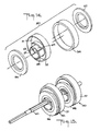
- the forward drive of the invention uses a plurality of composite rollers 50 of the construction shown in Fig. 14.
- Each roller 50 consists of a wide core or center element 51 having a circumference 52 which is concentric with its trilobular hole 53.
- On this circumferential surface is elastically mounted a frictional tire 54.
- Located eccentric to the trilobular hole are two cantilever shaft portions 55, one shown in Fig. 14 extending to the left, and the other extending to the right and not visible in Fig. 14.
- Thin rollers 56 and 57 with low friction surfaces are mounted on these shaft portion 55 and are retained by means of, for example, snap latches 58 and 59.
- One thin roller is positioned on each side of the wide center portion.
- the shaft portions 55 are eccentric with respect to the hole 53, and are positioned such that the thin outer roller portions are offset by about 180o. See also Fig. 19. The result is that each of the outer roller portions 56, 57 extend beyond the circumference 52 of the center roller portion 51 over a small arc of about 45o. The reason for allowing the thin roller to extend beyond the outside diameter of the center roller portion is explained below.
- pairs of these composite assemblies 50 are mounted in trilobe shafts 60 so as to establish an in-phase relationship between the roller pair such that the distance between the thin rollers 56, 57 appearing at, for instance, the 6 o'clock position, as shown in Fig. 15, remains constant as the trilobe shaft 60 is rotated.
- the trilobe shafting also allows the rollers to be rotatingly driven in this established orientation.
- Fig. 15 also shows the thin rollers 56, 57 extending beyond the circumference 52 of the core element 51 only over a short arc equal to about 90 degrees each. For the remainder of the 180° of the circumference, the core roller 51 extends beyond the thin rollers 56, 57.
- Figs. 16-18 show a side view of three of the assemblies of Fig. 15 located with respect to the horizontal deck 12 of a feeding device and supporting a stack of mail 11 on the frictional tire surface 54 of each roller assembly 50.
- the rotational drive supplied to the shafts 60 will move the stack in the direction shown by the arrow.
- the distance permitted between the shaft assemblies is related to the amount that the frictional tire is exposed above the horizontal deck.
- the distance between the shafts must be such that any envelope spanning the roller assemblies must be raised high enough by the frictional tire so that its sagging portion does not drape significantly on the deck.
- a 89 mm, 3.5 inch shaft center to center distance and a 5 mm, 0.2 inch tire to deck exposure can be used.
- Fig. 17 shows a similar view except the shafts have rotated clockwise (CW) about 45 , and the stack is now supported on the thin, eccentrically mounted rollers 56, 57.
- the lowest envelope in the stack is mainly subjected to the frictional force of the stack on top of it.
- the rollers 56, 57 below offer little frictional drag.
- the eccentrically mounted rollers 56, 57 must extend above the tire surface. In the preferred embodiment, they extend approximately 2.5 mm, 0.10 inches above the tire 54.
- the forward drive system in the preferred embodiment comprises three axial assemblies of two, two, and three composite rollers 50, respectively, as shown in Figs. 7-9.
- the shafts 60 of all three assemblies are essentially parallel, but are angled toward the registration wall 23, the angle indicated by 61 being about 10° to 16°, preferably about 13° .
- the shafts 60 are ganged together and driven by a common motor drive via a pulley 63, mounted under the deck 12, at the same rpm. See also Fig. 5.
- the same motor also belt drives the shaft 46 which rotates the cam 45.
- the thin rollers in one position extend above the deck activating the stack above.
- Fig. 19 and 20 are top views of the composite rollers, taken after 90° rotation, showing more clearly how in one position, one thin outer roller 56 will protrude to one side while the other thin outer roller 57 will protrude to the other side, and after 180° of rotation later, the other thin roller 57 will protrude, whereas at the 90° and 270° positions (Fig. 20), the center roller 51 protrudes.
- the effect on a letter 11 of the stack is shown in Figs. 21-24, showing 270° of rotation of the rollers.
- the rim of the core element 51 is of rubber with a high coefficient of friction and is relatively wide, whereas the thin rollers 56, 57 on opposite sides may be constructed of plastic with a low coefficient of friction.
- the envelopes are driven in the direction of rotation of rollers, downstream or forward, as well as toward the side wall 23 due to the angled position of the rollers (Figs. 7-9), as shown by the arrow 64 in Fig. 7.
- the actions is mostly vertical to fluff up the stack to reduce frictional forces between the envelopes.
- This combined forward and fluffing action causes the stack to begin shingling as illustrated in Fig. 18.
- the backward tilt of the deck illustrated in Figs. 10-12 also causes the stack to tilt backward as shown, which is important in reducing the weight of the stack on the lowermost envelopes and makes it easier for the singulator 15 to separate individual mail pieces.
- Fig. 10 shows a stack 11 of mail being deposited at the rear in the hopper section against wall 21 before activation of the drive.
- Fig. 11 shows how activation of the drive typically causes a section 11′ of the stack to be separated and driven forward. While the initial forward motion would tend to carry the whole stack forward, the fluffing rollers and the inclined deck tend to cause the upper part of the stack to tilt and fall backward against the rear wall 21, while a handful of envelopes 11′ are driven forward. The continued driving and fluffing action causes the initial handful 11′ to become shingled 11 ⁇ and thus pass in that condition under the barrier 28 and are driven forward into the singulator 15 by the belt drive 32. The continued forward drive then causes a second section 11′′′ to become separated from the stack 11 and undergo the same shingling action as the first section 11′, and this continues until the hopper becomes depleted of envelopes.
- phase is meant the orientation of the outer fluffing roller 56, 57 on one roller to that on another roller.
- In phase means that, viewed from the front, they are aligned.
- rollers 50 (Fig. 9) on each shaft 60 are all in phase with one another; and the rollers 50 in all three of the assemblies are also in phase with one another.
- Another feature that contributes to the pre-shingling action desired is a selection of frictional coefficients for the main center or drive roller 51 for the three roller assemblies.
- a material be chosen for the drive tire 54 for the three-roller assembly in the extreme upstream position which has the highest coefficient, for the middle two-roller assembly the lowest coefficient, and for the extreme downstream assembly a higher coefficient. This is because the principal advancing forces will be provided by the end roller assemblies. The higher coefficient is especially important for the upstream assembly because of the greater stack weight.
- Various types of rubber tires with different frictional coefficients are well-known and are available for this purpose.
- Figs. 7-9 also show the profile of the cam face 45 relative to the follower 43.
- the follower 43 is on the minor lobe of the cam face and the heavy force is being applied by spring 49 for tamping the flapped envelopes shown at 80.
- the major lobe of the cam face 45 has applied a reverse force to the wall 23 so that a light force now exists, which allows an envelope 80 to be advanced.
- Fig. 9 shows 180° of rotation later a return to the condition of Fig. 7.
- Fig. 25 illustrates a preferred embodiment for driving the cam 45 and roller assemblies.
- a motor 47 belt-drives 81 shaft 46 to which the cam 45 is attached.
- the shaft 46 in turn belt-drives 82 the adjacent roller shaft 60, which in turn belt-drives 83, 84 the end roller shafts 60. All the shafts of the drive are supported for rotation by end mounts 85, 86.
- the rollers 50 be driven such that the surface speed of the frictional tire 54 is in the range of about 610 to 813 mm. per second, 24-32 inches per second (ips).
- the surface speed is substantially greater than about 813 mm./s., 32 ips, then excessive vibration of the stack occurs that actually reduces the throughput.
- the surface speed falls below about 610 mm./s., 24 ips, then the mail pieces are not fluffing properly and producing the desired shingling profile. In the range indicated, we prefer the value of about 711 mm./s., 28 ips as optimum.
- Fig. 6 also shows, somewhat schematically, a stack of envelopes 11 whose flaps 67 extend into the slot 35 adjacent the deck edge 31. It is important that the stack 11 as it shingles continues to maintain the envelope flaps 67 in the slot.
- a further feature of the invention is structure downstream of the tamper wall 23, 24 but before the singulator 15 which is configured to guide the envelope flaps as they shingle down into the slot 35 and into the slot 30 in the singulator module.
- This structure consists of a vertical wall portion 70 located adjacent the tamper wall 24 and comprising a first surface 71 which slopes downstream, downward and toward the machine front, which intersects a second surface 72 which slopes downward and downstream, merging finally with a nearby vertical major surface 73.
- the surface 72 forms an angle of about 30 degrees-40 degrees, with 35 degrees being preferred, with a vertical plane. This angle substantially matches the angle formed by the leading edges of the ideal shingled stack of mail. It also matches the angle at which the bent lower part 28′ of the guide 28 extends.
- the surface 71 is adjusted to guide the flapped mail stack downstream toward the singulation area without causing any restriction or binding. A preferred angle for that surface is about 107 degrees with respect to the deck, and can vary about 5 degrees either way.
- the major surface 73 is angled backwards by a small angle of about 1 degrees to 4 degrees, preferably about 2 degrees.
- line 74 parallels the registration edge 31, and the angle indicated by numeral 75 represents about 2o.
- the surface 71 is angled indicated by reference numeral 76, preferably between about 35-39 degrees, preferably about 37 degrees, backward with respect to the surface 73.
- the nudger tamper subsystem i.e., the forward drive
- the nudger tamper subsystem is activated whenever there is mail in the hopper covering a hopper sensor (not shown).
- three reflective sensors are provided of which the covering of any one will activate the subsystem. Two are is located in the open area of the hopper and the other is located in the nip area of the singulation module. This ensures that the machine will continue to function while there is any mail piece waiting to be processed.
- each of the features shown and described herein, including the flap edge tamper subsystem, the angled nudger drive subsystem which drives the envelopes downstream as well as toward the side wall, the fluffing action of the drive wheels which together with the angled deck and back support provide the desired shingling action, are believed to be novel in themselves in the preferred environment of a high speed, mixed mail handling machine, and are also considered significant parts and contributors to the high performance of the overall front end feeder combination.
- some features of the present invention may be omitted, or used alone, or used with some but not all of the disclosed features.
- the present invention is intended to include individual features of the overall system disclosed herein, as well as combinations of some of the disclosed features without other disclosed features, as well as the overall combination.
- the shaft belt drives can be substituted by gearing, and the face cam by any other structure which intermittently forces back the push rod.
- a computer such as a microcontroller
- each roller includes a protruding high friction drive part over part of the circumference and a protruding low friction fluffing part over another part of the circumference.
- the phase relationships of the fluffing and drive parts may be different than as described for different kinds of articles.
- the invention as particularly disclosed and illustrated provides a front end feeder for high-speed processing of mixed mail, which can deliver mail pieces to a singulator at the rate of up to four per second, and which is capable of properly feeding mixed mail to a downstream singulator.
- a further advantage is that the machine is capable of properly feeding envelopes having a wide range of sizes and thicknesses to downstream modules for further processing.
Priority Applications (1)
| Application Number | Priority Date | Filing Date | Title |
|---|---|---|---|
| EP93202715A EP0581392B2 (de) | 1988-12-28 | 1989-12-08 | Zuführvorrichtung von gestapelten Werkstücken |
Applications Claiming Priority (2)
| Application Number | Priority Date | Filing Date | Title |
|---|---|---|---|
| US291024 | 1988-12-28 | ||
| US07/291,024 US4930764A (en) | 1988-12-28 | 1988-12-28 | Front end feeder for mail handling machine |
Related Child Applications (2)
| Application Number | Title | Priority Date | Filing Date |
|---|---|---|---|
| EP93202715.4 Division-Into | 1989-12-08 | ||
| EP93202715A Division EP0581392B2 (de) | 1988-12-28 | 1989-12-08 | Zuführvorrichtung von gestapelten Werkstücken |
Publications (4)
| Publication Number | Publication Date |
|---|---|
| EP0376520A2 true EP0376520A2 (de) | 1990-07-04 |
| EP0376520A3 EP0376520A3 (de) | 1991-01-30 |
| EP0376520B1 EP0376520B1 (de) | 1994-07-20 |
| EP0376520B2 EP0376520B2 (de) | 2000-11-02 |
Family
ID=23118509
Family Applications (2)
| Application Number | Title | Priority Date | Filing Date |
|---|---|---|---|
| EP89312843A Expired - Lifetime EP0376520B2 (de) | 1988-12-28 | 1989-12-08 | Stapelanschlag für die Zuführvorrichtung einer Postbehandlungsmaschine |
| EP93202715A Expired - Lifetime EP0581392B2 (de) | 1988-12-28 | 1989-12-08 | Zuführvorrichtung von gestapelten Werkstücken |
Family Applications After (1)
| Application Number | Title | Priority Date | Filing Date |
|---|---|---|---|
| EP93202715A Expired - Lifetime EP0581392B2 (de) | 1988-12-28 | 1989-12-08 | Zuführvorrichtung von gestapelten Werkstücken |
Country Status (6)
| Country | Link |
|---|---|
| US (1) | US4930764A (de) |
| EP (2) | EP0376520B2 (de) |
| JP (1) | JP2690376B2 (de) |
| AU (1) | AU625544B2 (de) |
| CA (1) | CA2004506C (de) |
| DE (2) | DE68916929T3 (de) |
Cited By (3)
| Publication number | Priority date | Publication date | Assignee | Title |
|---|---|---|---|---|
| US6241235B1 (en) | 1998-08-05 | 2001-06-05 | Francotyp-Postalia Ag & Co. | Apparatus for separating printed media |
| FR2924419A1 (fr) * | 2007-12-03 | 2009-06-05 | Secap Groupe Pitney Bowes Soc | Machine de traitement de documents |
| EP2072433A1 (de) | 2007-12-21 | 2009-06-24 | Postmark Inc. | Gerät zur Verarbeitung eines Papierstapels |
Families Citing this family (28)
| Publication number | Priority date | Publication date | Assignee | Title |
|---|---|---|---|---|
| US4953842A (en) * | 1988-12-28 | 1990-09-04 | Pitney Bowes Inc. | Mail thickness measuring apparatus |
| JP2670455B2 (ja) * | 1989-07-18 | 1997-10-29 | キヤノン株式会社 | 給紙装置 |
| US5074540A (en) * | 1990-11-05 | 1991-12-24 | Pitney Bowes Inc. | Document singulating apparatus |
| US5112037A (en) * | 1990-12-24 | 1992-05-12 | Pitney Bowes Inc. | Front feeder for large size mail handling machine |
| US5145162A (en) * | 1991-11-06 | 1992-09-08 | Roberts Systems, Inc. | Blank dispensing apparatus having oppositely rotating separator elements and method for use |
| US5238236A (en) * | 1992-11-12 | 1993-08-24 | Pitney Bowes Inc. | Document singulating apparatus for feeding upright documents of varying thickness |
| US5628504A (en) * | 1994-12-15 | 1997-05-13 | Pitney Bowes Inc. | Side guide for a mail handling machine |
| DE19605017C2 (de) * | 1996-01-31 | 1998-07-23 | Francotyp Postalia Gmbh | Anordnung zum Vorvereinzeln von Druckträgern |
| US5730439A (en) * | 1996-07-15 | 1998-03-24 | Pitney Bowes Inc. | Sheet feeder |
| JP3361979B2 (ja) * | 1996-12-09 | 2003-01-07 | ローレルバンクマシン株式会社 | 紙幣処理機の紙幣整列装置 |
| FR2759069B1 (fr) * | 1997-01-31 | 1999-04-23 | Neopost Ind | Dispositif d'alimentation en articles de courrier de dimensions variables |
| FR2759068B1 (fr) * | 1997-01-31 | 1999-04-23 | Neopost Ind | Dispositif d'alimentation en articles de courrier |
| DE19735382A1 (de) | 1997-08-14 | 1999-02-18 | Bell & Howell Co | Beschickungseinrichtung |
| US5971391A (en) * | 1997-10-03 | 1999-10-26 | Pitney Bowes Inc. | Nudger for a mail handling system |
| US6196392B1 (en) | 1997-12-23 | 2001-03-06 | Profold, Inc. | Method and apparatus for feeding and tabbing intermixed pieces of mail |
| US5946996A (en) * | 1997-12-31 | 1999-09-07 | The Staplex Company, Inc. | Automatic feed chadless envelope slitter |
| CH693177A5 (fr) * | 1998-09-02 | 2003-03-27 | Bobst Sa | Dispositif correcteur à rouleaux ou à bande pour l'alignement latéral, en cours de façonnage, d'articles en feuilles ou en plaques partiellement pliés dans une plieuse-colleuse. |
| CA2282093C (en) | 1999-09-14 | 2007-01-02 | Bell & Howell Gmbh | Charging apparatus |
| US6609662B2 (en) | 2000-02-01 | 2003-08-26 | Profold, Inc. | Debit card having secure scratch-off label strip with releasable layer and method of applying same |
| US6199757B1 (en) | 2000-02-01 | 2001-03-13 | Profold, Inc. | Debit card having scratch-off label strip and method of applying same |
| US6578874B1 (en) | 2000-03-13 | 2003-06-17 | Profold, Inc. | Method for correcting articles of mail and article of mail produced thereby |
| US6776406B2 (en) * | 2001-02-23 | 2004-08-17 | Ascom Hasler Mailing Systems, Inc. | Feeder and separator for separating and moving sheets from a stack of sheets |
| US6585251B2 (en) | 2001-11-13 | 2003-07-01 | Pitney Bowes Inc. | Articulating separator |
| FR2908756B1 (fr) | 2006-11-16 | 2009-02-13 | Neopost Technologies Sa | Dispositif de chargement automatique d'enveloppes. |
| US8246290B2 (en) * | 2007-09-27 | 2012-08-21 | Graphic Packaging International, Inc. | Carton feeder having friction reducing support shaft |
| FR2927069A1 (fr) | 2008-01-31 | 2009-08-07 | Neopost Technologies Sa | Dispositif de selection d'articles de courrier a filiere reglable |
| FR2949769B1 (fr) | 2009-09-08 | 2011-09-30 | Neopost Technologies | Dispositif d'alimentation a separation d'enveloppes amelioree |
| DE202016106124U1 (de) | 2016-11-01 | 2016-11-17 | Francotyp-Postalia Gmbh | Vereinzelungsstation |
Citations (2)
| Publication number | Priority date | Publication date | Assignee | Title |
|---|---|---|---|---|
| US4232860A (en) * | 1978-10-20 | 1980-11-11 | Automecha Ltd. | Paper feeder |
| US4676498A (en) * | 1982-12-10 | 1987-06-30 | Canon Kabushiki Kaisha | Sheet feeding apparatus |
Family Cites Families (28)
| Publication number | Priority date | Publication date | Assignee | Title |
|---|---|---|---|---|
| US1737670A (en) * | 1929-12-03 | Mailing machine | ||
| US551724A (en) * | 1895-12-17 | Paper-feeding machine | ||
| US1624899A (en) * | 1927-04-12 | Ances | ||
| US2390573A (en) * | 1943-04-22 | 1945-12-11 | Commercial Controls Corp | Envelope hopper for mail treating machines |
| US2841394A (en) * | 1955-03-23 | 1958-07-01 | Western Printing & Lithographi | Collector for flexible sheets |
| DE1561155A1 (de) † | 1967-04-28 | 1970-10-15 | Willi Kluge | Vereinzelungsvorrichtung fuer gestapelte Papierbogen |
| US3506258A (en) * | 1967-10-06 | 1970-04-14 | Measurement Research Center In | Document feeding mechanism |
| US3532338A (en) * | 1968-04-12 | 1970-10-06 | Ibm | Document handling device |
| US3674258A (en) † | 1970-10-19 | 1972-07-04 | Harris Intertype Corp | Method and apparatus for feeding stacked sheet material |
| DE2203626C2 (de) † | 1972-01-26 | 1983-03-03 | Kleindienst Gmbh & Co Kg, 8900 Augsburg | Vorrichtung zur Entnahme von Blättern aus einem Hauptstapel |
| BE795343A (fr) † | 1972-02-22 | 1973-05-29 | Pennsylvania Res Ass Inc | Machine d'entrainement, de separation et d'empilage de feuilles |
| US3905490A (en) * | 1972-05-26 | 1975-09-16 | Simon Ltd Henry | Case-making machinery |
| US3877531A (en) * | 1974-06-05 | 1975-04-15 | Pitney Bowes Inc | Automatic continuous mail handling system |
| DE2649959C2 (de) † | 1976-10-30 | 1985-09-12 | Karl Mohr | Vorrichtung zur Übergabe eines Teilstapels zu beschneidenden Gutes von einem Gesamtstapel in eine Rüttelstation |
| US4081181A (en) * | 1977-01-05 | 1978-03-28 | Multifold-International, Inc. | Discriminator supporting assembly |
| US4318540A (en) * | 1978-09-14 | 1982-03-09 | Burroughs Corporation | Constant spacing document feeder |
| US4428573A (en) * | 1979-08-20 | 1984-01-31 | Pitney Bowes Inc. | Mail handling apparatus |
| US4266762A (en) * | 1979-08-29 | 1981-05-12 | Xerox Corporation | Sheet alignment and feeding apparatus |
| JPS6050699B2 (ja) † | 1980-02-29 | 1985-11-09 | 株式会社リコー | 複写機、印刷機等のスタツキング装置 |
| CH646114A5 (de) * | 1980-05-12 | 1984-11-15 | Ferag Ag | Vorrichtung zum vereinzeln eines stapels gefalteter oder gebundener, mehrblaettriger druckprodukte. |
| KR890000910B1 (ko) * | 1984-06-29 | 1989-04-13 | 가부시기가이샤 히다찌세이사꾸쇼 | 지엽류의 분리 반송장치 |
| EP0215529B1 (de) * | 1985-09-20 | 1991-07-03 | Ascom Hasler AG | Vorrichtung zum Vereinzeln vorgefalzter faltbarer Blattstücke |
| US4715593A (en) * | 1985-12-02 | 1987-12-29 | Godlewski Edward S | Stack-supporting bottom feed conveyor |
| US4753432A (en) * | 1986-09-19 | 1988-06-28 | Pitney Bowes Inc. | Feeder module |
| US4744554A (en) † | 1986-10-10 | 1988-05-17 | Pitney Bowes Inc. | Deskewing device for mailing machine |
| WO1988002734A1 (en) * | 1986-10-14 | 1988-04-21 | Bryce Office Systems, Inc. | Envelope printing system for addresses and bar codes |
| US4817368A (en) * | 1986-10-14 | 1989-04-04 | J.A.D. Enterprises, Inc. | Mail inserting and collating apparatus |
| US4953842A (en) * | 1988-12-28 | 1990-09-04 | Pitney Bowes Inc. | Mail thickness measuring apparatus |
-
1988
- 1988-12-28 US US07/291,024 patent/US4930764A/en not_active Expired - Lifetime
-
1989
- 1989-12-04 CA CA002004506A patent/CA2004506C/en not_active Expired - Lifetime
- 1989-12-07 AU AU45996/89A patent/AU625544B2/en not_active Ceased
- 1989-12-08 DE DE68916929T patent/DE68916929T3/de not_active Expired - Fee Related
- 1989-12-08 EP EP89312843A patent/EP0376520B2/de not_active Expired - Lifetime
- 1989-12-08 DE DE68924859T patent/DE68924859T3/de not_active Expired - Fee Related
- 1989-12-08 EP EP93202715A patent/EP0581392B2/de not_active Expired - Lifetime
- 1989-12-19 JP JP1329384A patent/JP2690376B2/ja not_active Expired - Fee Related
Patent Citations (2)
| Publication number | Priority date | Publication date | Assignee | Title |
|---|---|---|---|---|
| US4232860A (en) * | 1978-10-20 | 1980-11-11 | Automecha Ltd. | Paper feeder |
| US4676498A (en) * | 1982-12-10 | 1987-06-30 | Canon Kabushiki Kaisha | Sheet feeding apparatus |
Cited By (4)
| Publication number | Priority date | Publication date | Assignee | Title |
|---|---|---|---|---|
| US6241235B1 (en) | 1998-08-05 | 2001-06-05 | Francotyp-Postalia Ag & Co. | Apparatus for separating printed media |
| FR2924419A1 (fr) * | 2007-12-03 | 2009-06-05 | Secap Groupe Pitney Bowes Soc | Machine de traitement de documents |
| EP2067722A1 (de) * | 2007-12-03 | 2009-06-10 | SECAP (Groupe Pitney Bowes) | Belegverarbeitungsmaschine |
| EP2072433A1 (de) | 2007-12-21 | 2009-06-24 | Postmark Inc. | Gerät zur Verarbeitung eines Papierstapels |
Also Published As
| Publication number | Publication date |
|---|---|
| DE68924859T2 (de) | 1996-03-28 |
| DE68924859D1 (de) | 1995-12-21 |
| JPH02225230A (ja) | 1990-09-07 |
| EP0581392A3 (de) | 1994-02-16 |
| EP0581392B2 (de) | 2001-08-22 |
| AU4599689A (en) | 1990-07-05 |
| AU625544B2 (en) | 1992-07-16 |
| EP0376520A3 (de) | 1991-01-30 |
| JP2690376B2 (ja) | 1997-12-10 |
| EP0581392B1 (de) | 1995-11-15 |
| EP0581392A2 (de) | 1994-02-02 |
| US4930764A (en) | 1990-06-05 |
| EP0376520B2 (de) | 2000-11-02 |
| DE68924859T3 (de) | 2002-03-28 |
| DE68916929T2 (de) | 1994-11-10 |
| DE68916929T3 (de) | 2001-03-29 |
| EP0376520B1 (de) | 1994-07-20 |
| CA2004506C (en) | 1999-09-07 |
| CA2004506A1 (en) | 1990-06-28 |
| DE68916929D1 (de) | 1994-08-25 |
Similar Documents
| Publication | Publication Date | Title |
|---|---|---|
| EP0376519B1 (de) | Stapelanschlag für die Zuführvorrichtung einer Postbehandlungsmaschine | |
| EP0581392B1 (de) | Zuführvorrichtung von gestapelten Werkstücken | |
| US4909499A (en) | Mail singulating apparatus | |
| EP1169571B1 (de) | Bogenfördervorrichtung und verfahren mit durchsatzkontrolle | |
| EP1111547B1 (de) | Vorrichtung zur Detektierung der ordnungsgemässen Zuführungsposition von Poststücken | |
| EP0906880B1 (de) | Fördervorrichtung für ein Posthandhabungssystem | |
| US6536756B2 (en) | Aligner mechanism for a mail handling system | |
| US4775142A (en) | Roller apparatus for side registration of documents | |
| US20090152796A1 (en) | Multimode stack and shingle document feeder | |
| EP0054708B1 (de) | Vorrichtung zum Verarbeiten von Dokumenten | |
| AU627799B2 (en) | Front end feeder for mail handling machine | |
| US5431385A (en) | Ingestion roller for mixed mail feeder | |
| US6817608B2 (en) | Method and apparatus for stacking mailpieces in consecutive order | |
| US7427063B2 (en) | Shingle media item feed tray with spring loaded self locking sled | |
| EP1783076A2 (de) | Vorrichtung zum Zuführen von Medienprodukten in Schuppenformation | |
| US4635919A (en) | Floating document throat | |
| US6612211B1 (en) | Apparatus for opening envelopes | |
| US5445371A (en) | Apparatus and method for buckling a sheet | |
| WO1982000994A1 (en) | Separator mechanism for envelope or sheet feeding apparatus | |
| JPS59223634A (ja) | 物品の供給装置 | |
| GB2258458A (en) | Method and apparatus for aligning while changing direction of flat articles |
Legal Events
| Date | Code | Title | Description |
|---|---|---|---|
| PUAI | Public reference made under article 153(3) epc to a published international application that has entered the european phase |
Free format text: ORIGINAL CODE: 0009012 |
|
| AK | Designated contracting states |
Kind code of ref document: A2 Designated state(s): BE CH DE FR GB IT LI NL SE |
|
| PUAL | Search report despatched |
Free format text: ORIGINAL CODE: 0009013 |
|
| AK | Designated contracting states |
Kind code of ref document: A3 Designated state(s): BE CH DE FR GB IT LI NL SE |
|
| 17P | Request for examination filed |
Effective date: 19910702 |
|
| 17Q | First examination report despatched |
Effective date: 19930310 |
|
| GRAA | (expected) grant |
Free format text: ORIGINAL CODE: 0009210 |
|
| AK | Designated contracting states |
Kind code of ref document: B1 Designated state(s): BE CH DE FR GB IT LI NL SE |
|
| XX | Miscellaneous (additional remarks) |
Free format text: TEILANMELDUNG 93202715.4 EINGEREICHT AM 08/12/89. |
|
| REF | Corresponds to: |
Ref document number: 68916929 Country of ref document: DE Date of ref document: 19940825 |
|
| ITF | It: translation for a ep patent filed |
Owner name: STUDIO FERRARIO |
|
| ET | Fr: translation filed | ||
| EAL | Se: european patent in force in sweden |
Ref document number: 89312843.9 |
|
| PLBI | Opposition filed |
Free format text: ORIGINAL CODE: 0009260 |
|
| PLBI | Opposition filed |
Free format text: ORIGINAL CODE: 0009260 |
|
| 26 | Opposition filed |
Opponent name: NEOPOST LTD Effective date: 19950405 |
|
| 26 | Opposition filed |
Opponent name: FRANCOTYP-POSTALIA GMBH Effective date: 19950420 Opponent name: NEOPOST LTD Effective date: 19950405 |
|
| NLR1 | Nl: opposition has been filed with the epo |
Opponent name: NEOPOST LTD |
|
| NLR1 | Nl: opposition has been filed with the epo |
Opponent name: FRANCOTYP-POSTALIA GMBH Opponent name: NEOPOST LTD |
|
| PLAB | Opposition data, opponent's data or that of the opponent's representative modified |
Free format text: ORIGINAL CODE: 0009299OPPO |
|
| R26 | Opposition filed (corrected) |
Opponent name: NEOPOST LTD * 950420 FRANCOTYP-POSTALIA AKTIENGESE Effective date: 19950405 |
|
| NLR1 | Nl: opposition has been filed with the epo |
Opponent name: NEOPOST LTD Opponent name: FRANCOTYP-POSTALIA AKTIENGESELLSCHAFT & CO. |
|
| PLBO | Opposition rejected |
Free format text: ORIGINAL CODE: EPIDOS REJO |
|
| APAC | Appeal dossier modified |
Free format text: ORIGINAL CODE: EPIDOS NOAPO |
|
| APAE | Appeal reference modified |
Free format text: ORIGINAL CODE: EPIDOS REFNO |
|
| APAC | Appeal dossier modified |
Free format text: ORIGINAL CODE: EPIDOS NOAPO |
|
| APAC | Appeal dossier modified |
Free format text: ORIGINAL CODE: EPIDOS NOAPO |
|
| PLAW | Interlocutory decision in opposition |
Free format text: ORIGINAL CODE: EPIDOS IDOP |
|
| PUAH | Patent maintained in amended form |
Free format text: ORIGINAL CODE: 0009272 |
|
| STAA | Information on the status of an ep patent application or granted ep patent |
Free format text: STATUS: PATENT MAINTAINED AS AMENDED |
|
| 27A | Patent maintained in amended form |
Effective date: 20001102 |
|
| AK | Designated contracting states |
Kind code of ref document: B2 Designated state(s): BE CH DE FR GB IT LI NL SE |
|
| ITF | It: translation for a ep patent filed |
Owner name: STUDIO FERRARIO |
|
| XX | Miscellaneous (additional remarks) |
Free format text: TEILANMELDUNG 93202715.4 EINGEREICHT AM 08/12/89. |
|
| REG | Reference to a national code |
Ref country code: CH Ref legal event code: AEN Free format text: AUFRECHTERHALTUNG DES PATENTES IN GEAENDERTER FORM |
|
| ET3 | Fr: translation filed ** decision concerning opposition | ||
| NLR2 | Nl: decision of opposition | ||
| NLR3 | Nl: receipt of modified translations in the netherlands language after an opposition procedure | ||
| REG | Reference to a national code |
Ref country code: GB Ref legal event code: IF02 |
|
| PGFP | Annual fee paid to national office [announced via postgrant information from national office to epo] |
Ref country code: NL Payment date: 20021121 Year of fee payment: 14 |
|
| PGFP | Annual fee paid to national office [announced via postgrant information from national office to epo] |
Ref country code: BE Payment date: 20021218 Year of fee payment: 14 |
|
| PG25 | Lapsed in a contracting state [announced via postgrant information from national office to epo] |
Ref country code: BE Free format text: LAPSE BECAUSE OF NON-PAYMENT OF DUE FEES Effective date: 20031231 |
|
| BERE | Be: lapsed |
Owner name: *PITNEY BOWES INC. Effective date: 20031231 |
|
| PG25 | Lapsed in a contracting state [announced via postgrant information from national office to epo] |
Ref country code: NL Free format text: LAPSE BECAUSE OF NON-PAYMENT OF DUE FEES Effective date: 20040701 |
|
| NLV4 | Nl: lapsed or anulled due to non-payment of the annual fee |
Effective date: 20040701 |
|
| APAH | Appeal reference modified |
Free format text: ORIGINAL CODE: EPIDOSCREFNO |
|
| PGFP | Annual fee paid to national office [announced via postgrant information from national office to epo] |
Ref country code: SE Payment date: 20061227 Year of fee payment: 18 |
|
| PGFP | Annual fee paid to national office [announced via postgrant information from national office to epo] |
Ref country code: IT Payment date: 20061231 Year of fee payment: 18 |
|
| REG | Reference to a national code |
Ref country code: CH Ref legal event code: PFA Owner name: PITNEY BOWES INC. Free format text: PITNEY BOWES INC.#WORLD HEADQUARTERS#STAMFORD/CT (US) -TRANSFER TO- PITNEY BOWES INC.#WORLD HEADQUARTERS#STAMFORD/CT (US) |
|
| PGFP | Annual fee paid to national office [announced via postgrant information from national office to epo] |
Ref country code: CH Payment date: 20071228 Year of fee payment: 19 |
|
| PGFP | Annual fee paid to national office [announced via postgrant information from national office to epo] |
Ref country code: GB Payment date: 20071227 Year of fee payment: 19 |
|
| PGFP | Annual fee paid to national office [announced via postgrant information from national office to epo] |
Ref country code: DE Payment date: 20080131 Year of fee payment: 19 |
|
| PGFP | Annual fee paid to national office [announced via postgrant information from national office to epo] |
Ref country code: FR Payment date: 20071217 Year of fee payment: 19 |
|
| EUG | Se: european patent has lapsed | ||
| PG25 | Lapsed in a contracting state [announced via postgrant information from national office to epo] |
Ref country code: SE Free format text: LAPSE BECAUSE OF NON-PAYMENT OF DUE FEES Effective date: 20071209 |
|
| PLAB | Opposition data, opponent's data or that of the opponent's representative modified |
Free format text: ORIGINAL CODE: 0009299OPPO |
|
| REG | Reference to a national code |
Ref country code: CH Ref legal event code: PL |
|
| GBPC | Gb: european patent ceased through non-payment of renewal fee |
Effective date: 20081208 |
|
| PG25 | Lapsed in a contracting state [announced via postgrant information from national office to epo] |
Ref country code: IT Free format text: LAPSE BECAUSE OF NON-PAYMENT OF DUE FEES Effective date: 20071208 |
|
| REG | Reference to a national code |
Ref country code: FR Ref legal event code: ST Effective date: 20090831 |
|
| PG25 | Lapsed in a contracting state [announced via postgrant information from national office to epo] |
Ref country code: DE Free format text: LAPSE BECAUSE OF NON-PAYMENT OF DUE FEES Effective date: 20090701 Ref country code: LI Free format text: LAPSE BECAUSE OF NON-PAYMENT OF DUE FEES Effective date: 20081231 Ref country code: CH Free format text: LAPSE BECAUSE OF NON-PAYMENT OF DUE FEES Effective date: 20081231 |
|
| PG25 | Lapsed in a contracting state [announced via postgrant information from national office to epo] |
Ref country code: GB Free format text: LAPSE BECAUSE OF NON-PAYMENT OF DUE FEES Effective date: 20081208 |
|
| PG25 | Lapsed in a contracting state [announced via postgrant information from national office to epo] |
Ref country code: FR Free format text: LAPSE BECAUSE OF NON-PAYMENT OF DUE FEES Effective date: 20081231 |