EP0906880B1 - Fördervorrichtung für ein Posthandhabungssystem - Google Patents
Fördervorrichtung für ein Posthandhabungssystem Download PDFInfo
- Publication number
- EP0906880B1 EP0906880B1 EP98118649A EP98118649A EP0906880B1 EP 0906880 B1 EP0906880 B1 EP 0906880B1 EP 98118649 A EP98118649 A EP 98118649A EP 98118649 A EP98118649 A EP 98118649A EP 0906880 B1 EP0906880 B1 EP 0906880B1
- Authority
- EP
- European Patent Office
- Prior art keywords
- stack
- nudger
- arm
- force
- Prior art date
- Legal status (The legal status is an assumption and is not a legal conclusion. Google has not performed a legal analysis and makes no representation as to the accuracy of the status listed.)
- Expired - Lifetime
Links
- 238000012545 processing Methods 0.000 claims description 17
- 230000007246 mechanism Effects 0.000 claims description 12
- 230000033001 locomotion Effects 0.000 claims description 7
- 238000000034 method Methods 0.000 claims description 5
- 230000008569 process Effects 0.000 claims description 5
- 230000004044 response Effects 0.000 claims description 5
- 230000007423 decrease Effects 0.000 claims description 4
- 238000004891 communication Methods 0.000 claims description 2
- 230000005484 gravity Effects 0.000 claims description 2
- 238000000926 separation method Methods 0.000 description 6
- 230000008901 benefit Effects 0.000 description 5
- 230000000903 blocking effect Effects 0.000 description 5
- 238000013461 design Methods 0.000 description 4
- 230000032258 transport Effects 0.000 description 4
- 230000001133 acceleration Effects 0.000 description 3
- 230000009471 action Effects 0.000 description 3
- 238000000418 atomic force spectrum Methods 0.000 description 3
- 230000001105 regulatory effect Effects 0.000 description 3
- 230000001419 dependent effect Effects 0.000 description 2
- 230000003993 interaction Effects 0.000 description 2
- 238000012986 modification Methods 0.000 description 2
- 230000004048 modification Effects 0.000 description 2
- 239000000758 substrate Substances 0.000 description 2
- 230000003466 anti-cipated effect Effects 0.000 description 1
- 230000033228 biological regulation Effects 0.000 description 1
- 230000006835 compression Effects 0.000 description 1
- 238000007906 compression Methods 0.000 description 1
- 230000000737 periodic effect Effects 0.000 description 1
- 238000004513 sizing Methods 0.000 description 1
- 238000012360 testing method Methods 0.000 description 1
- 238000011144 upstream manufacturing Methods 0.000 description 1
Images


Classifications
-
- B—PERFORMING OPERATIONS; TRANSPORTING
- B65—CONVEYING; PACKING; STORING; HANDLING THIN OR FILAMENTARY MATERIAL
- B65H—HANDLING THIN OR FILAMENTARY MATERIAL, e.g. SHEETS, WEBS, CABLES
- B65H1/00—Supports or magazines for piles from which articles are to be separated
- B65H1/02—Supports or magazines for piles from which articles are to be separated adapted to support articles on edge
- B65H1/025—Supports or magazines for piles from which articles are to be separated adapted to support articles on edge with controlled positively-acting mechanical devices for advancing the pile to present the articles to the separating device
-
- B—PERFORMING OPERATIONS; TRANSPORTING
- B65—CONVEYING; PACKING; STORING; HANDLING THIN OR FILAMENTARY MATERIAL
- B65H—HANDLING THIN OR FILAMENTARY MATERIAL, e.g. SHEETS, WEBS, CABLES
- B65H2511/00—Dimensions; Position; Numbers; Identification; Occurrences
- B65H2511/50—Occurence
- B65H2511/515—Absence
-
- B—PERFORMING OPERATIONS; TRANSPORTING
- B65—CONVEYING; PACKING; STORING; HANDLING THIN OR FILAMENTARY MATERIAL
- B65H—HANDLING THIN OR FILAMENTARY MATERIAL, e.g. SHEETS, WEBS, CABLES
- B65H2513/00—Dynamic entities; Timing aspects
- B65H2513/50—Timing
-
- B—PERFORMING OPERATIONS; TRANSPORTING
- B65—CONVEYING; PACKING; STORING; HANDLING THIN OR FILAMENTARY MATERIAL
- B65H—HANDLING THIN OR FILAMENTARY MATERIAL, e.g. SHEETS, WEBS, CABLES
- B65H2515/00—Physical entities not provided for in groups B65H2511/00 or B65H2513/00
- B65H2515/30—Forces; Stresses
-
- B—PERFORMING OPERATIONS; TRANSPORTING
- B65—CONVEYING; PACKING; STORING; HANDLING THIN OR FILAMENTARY MATERIAL
- B65H—HANDLING THIN OR FILAMENTARY MATERIAL, e.g. SHEETS, WEBS, CABLES
- B65H2601/00—Problem to be solved or advantage achieved
- B65H2601/10—Ensuring correct operation
- B65H2601/11—Clearing faulty handling, e.g. jams
-
- B—PERFORMING OPERATIONS; TRANSPORTING
- B65—CONVEYING; PACKING; STORING; HANDLING THIN OR FILAMENTARY MATERIAL
- B65H—HANDLING THIN OR FILAMENTARY MATERIAL, e.g. SHEETS, WEBS, CABLES
- B65H2701/00—Handled material; Storage means
- B65H2701/10—Handled articles or webs
- B65H2701/19—Specific article or web
- B65H2701/1916—Envelopes and articles of mail
Definitions
- the present invention relates to a nudger for a mail handling system.
- the processing and handling of mailpieces consumes an enormous amount of human and financial resources, particularly if the processing of the mailpieces is done manually.
- the processing and handling of mailpieces not only takes place at the Postal Service, but also occurs at each and every business or other site where communication via the mail delivery system is utilized. That is, various pieces of mail generated by a plurality of departments and individuals within a company need to be collected, sorted, addressed, and franked as part of the outgoing mail process. Additionally, incoming mail needs to be collected and sorted efficiently to ensure that it gets to the addressee in a minimal amount of time.
- the stack of "mixed mail" is first loaded onto some type of conveying system for subsequent sorting into individual pieces.
- the stack of mixed mail is moved as a stack by an external force to, for example, a shingling device.
- the shingling device applies a force to the lead mailpiece in the stack to initiate the separation of the lead mailpiece from the rest of the stack by shingling it slightly relative to the stack.
- the shingled mailpieces are then transported downstream to, for example, a separating device which completes the separation of the lead mailpiece from the stack so that individual pieces of mail are transported further downstream for subsequent processing.
- inter-document stack forces exist between each of the mailpieces that are in contact with each other in the stack.
- the inter-document stack forces are created by the stack advance mechanism, the frictional forces between the documents, and potentially electrostatic forces that may exist between the documents.
- the inter-document forces tend to oppose the force required to shear the lead mailpiece from the stack.
- the interaction of the force used to drive the shingled stack toward the separator and the forces at the separator can potentially cause a thin mailpiece to be damaged by being buckled as it enters the separator.
- the structure used to separate a stack of mixed mail must take into account the counterproductive nature of the forces acting on the mailpieces and be such that an effective force profile acts on the mailpieces throughout their processing cycle so that effective and reliable mailpiece separation and transport at very high processing speeds (such as four mailpieces per second) can be accomplished without physical damage occurring to the mailpieces.
- the desired force profile acting on a particular mailpiece is dependent upon the size, thickness, configuration, weight, and substrate of the individual mailpiece being processed, the design of a mixed mail feeder which can efficiently and reliably process a wide range of different types of mixed mailpieces has been extremely difficult to achieve.
- a nudger including means for applying a feed force to a lead mailpiece of the stack of mixed mail to feed the lead mailpiece of the stack along a mailpiece feed path, the applying means being moveable between first and second positions; means for biasing the applying means against a face of the lead mailpiece thereby generating a stack force against a stack of mixed mail; and a stack advance mechanism for moving the stack of mixed mail so that the face of the lead mailpiece contacts the applying means; wherein at times when the applying means is in the first position the stack advance mechanism moves the stack of mixed mail in the direction of the applying means causing the applying means to move from the first position to the second position against the biasing means such that the stack force increases causing a corresponding increase in the feed force; and further wherein at times when the applying means is in the second position the stack advance mechanism stops moving the stack of mixed mail and the applying means continuously feeds mailpieces away from the stack of mixed mail along the mailpiece feed path thereby continuously reducing the size of the stack of mixed mail so that the biasing
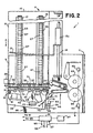
- Mixed mail feeder 1 separates individual mailpieces 3 from a stack of mixed mail generally designated at 5 and transports the individual mailpieces 3 to a subsequent mail processing station 7.
- Mail processing station 7 can be any one of a plurality of devices such as a meter for printing postage on the mailpiece 3, an OCR reader for reading addresses off of the mailpiece 3, a sorting device for sorting the individual mailpieces 3 to designated bins or areas, or even a scale that weighs the mailpiece.
- the key point is that the mixed mail feeder 1 functions to separate individual mailpieces 3 from a stack of mixed mail 5 and deliver the individual mailpieces 3 sequentially to the mail processing station 7.
- Mixed mail feeder 1 includes a table 9 upon which all of the components of the mixed mail feeder 1 are mounted. At an input end of the mixed mail feeder 1, generally designated by the arrow 11, the stack of mixed mail 5 is placed on edge by an operator in front of a guide wall 13. Guide wall 13 acts as a support against which the stack of mixed mail 5 rests. Moreover, guide wall 13 includes a cylindrical portion 13a which is mounted to slide on a guide rod 15 fixedly attached to platform 10 which is mounted to table 9.
- Platform 10 has first and second slots 17, 19, in a horizontal surface 21 thereof.
- the slots 17, 19 each permit a top portion of a respective individual continuous belt 23, 25 to project therethrough.
- Belts 23, 25 each have a plurality of individual track portions 27 over the full extent of the belts 23, 25.
- the bottom of guide wall 13 removably fits in adjacent track portions 27 of each of belts 23 and 25 so that guide wall 13 moves with belts 23, 25 in the direction of arrow A (alternatively, a single belt can be used).
- the cylindrical portion 13a slides along guide rod 15 to keep the standing orientation of guide wall 13 in the position shown in Fig. 1.
- Continuous belts 23, 25 are mounted in a conventional manner around a pulley at each end (not shown).
- One pulley is an idler pulley while the other is driven by a motor 29.
- the motor 29 drives a common shaft (not shown) connected to the drive pulleys of each of the belts 23, 25 such that the belts 23, 25 will be driven at the same velocity to move around their respective idler and driven pulleys.
- the guide wall 13 moves therewith so that the entire stack of mixed mail 5 is moved toward a nudger wall 31.
- the stack of mixed mail 5 will have individual mailpieces 3 moved from the stack downstream so that the stack of mixed mailpieces is continuously reduced in size.
- the guide wall 13 can be lifted out of the individual tracks 27 of the belts 23, 25 by pulling the guide wall 13 up to rotate, via the cylindrical portion 13a, about the guide rod 15. Once the bottom of the guide wall 13 is clear of the individual tracks 27 of the belts 23, 25, it can be slid backward in the opposite direction from that of arrow A and placed in a desired position to receive additional mixed mail.
- nudger wall 31 includes a plurality of rollers 33 mounted therein in a conventional manner to be freely rotatable. Furthermore, nudger wall 31 has a cutout 35 in a lower comer thereof through which driven nudger rollers 37 project. Moreover, a plurality of roller bars 38 are rotatably mounted in a conventional manner in a slot 40 of platform 10. Thus, as guide wall 13 pushes the stack of mixed mail 5 toward nudger wall 31, individual pieces of mail 3 fall off the end of belts 23, 25 on top of the rollers 38 and into contact with the nudger rollers 37. While in the preferred embodiment the roller bars 38 are not driven, they could be driven to provide additional forward feed force to the mailpiece 3. In one embodiment, a continuous belt (not shown) is driven around the roller bars 38. The use of the continuous belt provides a greater coefficient of friction as compared to the roller bars and thus improves the feed force and provides for a simple drive structure.
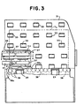
- the nudger rollers 37 are mounted to be driven into rotation within a nudger arm 39.
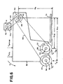
- the four nudger rollers 37 are driven together by a motor 41, mounted on nudger arm 39, via a drive train 43 as shown schematically in Figure 2 and in detail in Figure 4.
- all of the nudger rollers 37 are driven into rotation in a clockwise direction. Accordingly, as the stack of mixed mail 5 is moved toward nudger wall 31, the lead mailpiece 3a is forced into contact with the nudger rollers 37.
- the force of the driven nudger rollers 37 acts against the lead mailpiece 3a to move the mailpiece 3a in the direction of a conventional separator device 45, thereby shingling the lead mailpiece 3a from the stack of mixed mail 5 as shown in Figures 1 and 2.
- the shingled stack is then transported to the nip of separator 45 which operates in a conventional manner to separate the lead mailpiece 3a from the shingled stack and deliver it to take-away rollers 65 which transport the individual lead mailpiece 3a further downstream to mail processing station 7.
- Motor 41 has a shaft 41a connected to a pulley 42.
- a continuous belt 44 is disposed around pulley 42 and a second pulley 46.
- Pulley 46 is fixedly mounted to a rotatable shaft 48 mounted in nudger arm 39.
- Fixedly mounted to shaft 48 is a third pulley 50.
- Additional shafts 52, 54 are also rotatably mounted in nudger arm 39 and respectively have fourth and fifth pulleys 56, 58 fixedly mounted thereto.
- Nudger rollers 37 are mounted on a corresponding one of shafts 52, 54. Accordingly, as motor 41 rotates pulley 42 in the clockwise direction of Fig.
- pulley 46 and hub 48 are driven in the clockwise direction as well. Since a continuous belt 60 passes around pulleys 50, 56, and 58, shafts 52, 54 are forced to rotate in the clockwise direction causing a corresponding rotational movement in all of nudger rollers 37.
- the normal force is created by a spring 49 that is fixedly mounted at one end to the nudger wall 31 and at its other end to a mounting platform 62 of nudger arm 39.
- the nudger arm 39 is pivotally mounted about a conventional pivot structure 51 so that the spring 49 biases the nudger rollers 37 through the cutout 35 and into contact with the lead mailpiece 3a.
- the nudger arm 39 is forced to rotate in the clockwise direction of Figure 2 around pivot structure 51 in opposition to the biasing force of the spring 49.
- the force exerted by the spring 49 is continually increased by a known amount.
- the thin and untabbed mailpieces are fed by the nudger rollers 37 into the separator 45, they can easily be buckled and damaged due to the feeding force of the nudger rollers 37 and the forces exerted by separator 45. Additionally, if the guide wall 13 is advanced too far toward the nudger wall 31 the stack of mixed mail 5 will be clamped in place preventing the feeding of individual mailpieces from stack 5. To prevent this from happening, the contact point of the nudger rollers 37 against the lead mailpiece 3a is always maintained closer to the stack 5 than the facing surface of the nudger wall 31 is to the stack 5.
- the normal force which is created by the positioning of the mailpiece stack 5 against the nudger rollers 37 and the corresponding force created by the extension of spring 49 needs to be maintained in a range of 1-2 newtons in order to ensure that the various types of mixed mailpieces 3 which may be processed are properly shingled and fed vertically into the throat of separator 45 without being damaged or stalled at nudger wall 31.
- the normal force is provided by the extension of spring 49, it can be controlled by accurately regulating the position of nudger arm 39 which correspondingly regulates the extension of spring 49. That is, since the normal force applied by spring 49 is directly proportional to its extension, the normal force that it applies to the stack of mixed mail 5 is controlled by regulating the extension of spring 49.
- the aforementioned control of the extension of spring 49 and rotation of nudger arm 39 is accomplished via the utilization of conventional through-beam sensors 53, 55, and 57 and a finger 59 which projects from nudger arm 39.
- the finger 59 will move between the three sensors 53, 55 and 57.
- a signal is sent by the respective blocked through-beam sensor to a mixed mail feeder microprocessor 61 indicating the position of the finger 59 at the blocked sensor.
- the known position of the finger 59 corresponds to a known position of the nudger arm 39 and a known amount of extension of the spring 49.
- the microprocessor 61 If the finger 59 is blocking the beam of the first sensor 53, the microprocessor 61 knows that the nudger rollers 37 are at their innermost position relative to the stack of mixed mail 5. At this position, the normal force exerted by spring 49 is below the desired minimum value of 1 newton and must be increased. The increase in normal force is created when the microprocessor 61, in response to a signal from sensor 53, energizes the motor 29 to move the belts 23 and 25 such that the guide wall 13 advances the mixed mail stack 5 into the nudger rollers 37. The motor 29 will advance the stack of mixed mail 5 until the nudger arm 39 pivots about pivot structure 51 to the position where finger 59 blocks the through-beam sensor 55.
- the sensor 55 sends a signal to microprocessor 61 which in turn deenergizes motor 29 stopping the advance of the stack of mixed mail 5 toward the nudger rollers 37.
- the nudger rollers 37 are considered to be in the "out" position where the maximum desired normal force is being exerted on the lead mailpiece 3a due to the extension of the spring 49.
- the nudger rollers 37 gradually move toward the innermost normal force position.
- microprocessor 61 When the nudger arm 39 has rotated inwardly such that the nudger rollers 37 are in the innermost normal force position, microprocessor 61 receives a signal from sensor 53 and energizes motor 29 to advance the stack of mail 5 until the second sensor 55 is blocked by the finger 59. In this manner, constant regulation of the normal force in the predetermined range is maintained.
- the automatic control of the normal force only uses the sensors 53 and 55 to ensure that the normal force generated by the nudger rollers 37 stays within the predetermined desired normal force range.
- a second tier of additional stack force is applied if it is determined that a mailpiece 3 has stalled at the nudger rollers 37 or at the separator 45. That is, it is possible, since the mixed mail feeder 1 is designed to handle many different types of mixed mail, that a very heavy piece of mail may have stalled (become stuck) at the nudger rollers 37 or separator 45.
- the mixed mail feeder 1 determines that a stall has occurred is by the use of a through-beam sensor 63, which is positioned proximate to the nip of takeaway rollers 65. Takeaway rollers 65, in a conventional manner, receive individual mailpieces from separator 45 and move the individual mailpieces 3 downstream.
- the takeaway rollers 65 feed a first mailpiece and do not process a second mailpiece 3 downstream in a predetermined period of time of, for example, 1,000 msec
- the through-beam of sensor 63 does not detect the lead edge of the second mailpiece during that same predetermined time period. If the microprocessor 61 does not receive an indication from the sensor 63 that a leading edge of the second mailpiece has passed thereby within the predetermined period of time, microprocessor 61 is programmed to assume that a stall has occurred somewhere upstream. Microprocessor 61 then energizes motor 29 to cause the stack of mixed mail 5 to be moved toward the nudger wall 31. The nudger arm 39 is forced to rotate about the pivot point 51 and the spring 49 is further extended.
- nudger arm 39 is advanced to block the third sensor 57.
- a stalled normal force which is larger than the maximum normal force applied under normal operating conditions, is being exerted on the lead mailpiece 3a by the nudger rollers 37 and the motor 29 is rendered inoperative by microprocessor 61.
- the increased normal force can simply be due to the further extension of the spring 49 as the nudger arm 39 is rotated from its position blocking sensor 55 to its position blocking sensor 57, or can be further increased by the force of an additional compression spring 66 which only contacts the nudger arm 39 to provide an additional spring force thereto when the nudger arm 39 moves beyond the position from the blocking of sensor 55 toward the blocking of sensor 57.
- the takeaway sensor 63 will provide an input to the microprocessor 61 identifying that the lead edge of the stalled mailpiece has passed thereby and the processing of individual mailpieces 3 will continue by driving the nudger rollers 37 until the nudger arm 39 moves to a position where the first sensor 53 is blocked by finger 59. At this position, the system will operate as discussed above, regulating a force profile by maintaining the position of nudger arm 39 between the sensors 53 and 55.
- the microprocessor 61 In the event however, that even the additional normal force provided by the movement of the nudger arm 39 to block the sensor 57 does not correct the stalled problem, the microprocessor 61, after a predetermined period of time, will provide an input to the user via a display 67 identifying the stalled condition and advising that operator intervention is required to correct the problem.
- the microprocessor 61 controls all of the motors typically associated with the stack advance, shingling device, separator, and take away rollers and includes known clock structure for determining the predetermined time periods discussed above. Empirical testing has shown that for the anticipated mixed mailpiece profile the additional normal force applied during movement of finger 59 from sensor 55 to sensor 57 goes from 2 to 5 newtons.
- the spring 66 is selected and preloaded so that upon initial engagement with arm 39 the total normal force immediately goes to 4 newtons.
- a different mechanism is used to provide additional force in the situation where stalled mail is detected. That is, once the microprocessor 61 determines that a stall has occurred, utilization of a solenoid 71 and another spring 73 provides additional normal force in an attempt to overcome the stalled situation.
- the solenoid 71 is fixedly mounted to the platform 9 and the spring 73 has one end fixedly mounted to the nudger arm 39 and a second end fixedly mounted to a moveable plunger 75 of solenoid 71.
- the spring 73 is slack, thereby providing no additional normal spring force.
- the microprocessor 61 energizes the solenoid 71 to withdraw the plunger 75 such that the spring 73 is extended to provide an additional normal force to the mixed mail stack 5 via the nudger rollers 37.
- the force applied by the solenoid/spring combination 71/73 can be consistently applied for a predetermined period of time or can be pulsed to help the stalled mail break away.
- different levels of force can be applied by the spring 73 and solenoid 71 combination over a predetermined time period in an attempt to break the stalled mailpiece away.
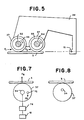
- a more simplified mechanism for providing an increased normal force on the stack of mixed mail 5 is to offset the pivot of the nudger arm 39 so that the reaction force between the mail and the nudger rollers 37 pulls the nudger arm 39 against the mailpieces 3, thereby providing additional stack force.
- This embodiment is best explained by first referring to Figure 5 which schematically shows the relationship of nudger rollers 37 to the pivot point 51 of nudger arm 39 in the embodiment of Figures 1 and 2. As shown, when nudger rollers 37 are driven, reaction forces F 1 and F 2 are respectively created due to the coefficient of friction between the nudger rollers 37 and the mailpiece 3.
- motor 41 is no longer mounted on nudger arm 39 but is fixedly mounted to table 9 (not shown).
- the remaining structure of the nudger roller 37 drive system is the same as described in connection with Figure 4.
- nudger arm 39 is mounted to pivot along the rotational axis of shaft 48.
- the rotational axis of shaft 48 is located a distance "M A " from the direction of the reaction forces F 1 and F 2 such that respective moments "F 1 M A " and "F 1 M A " are created about the pivot axis of shaft 48. Since the sum of the moments about the axis of shaft 48 is equal to zero, the following equation results.
- each nudger roller 37 has an offset center of gravity (CG) 72.
- CG center of gravity
- microprocessor 61 controls motor 41 to accelerate the nudger rollers 37.
- the acceleration of the CG 72 results in a force F A and a corresponding increased stack force F B .
- a conventional encoder 74 operatively associated with shaft 54 provides signals to motor 41 indicative of the position of shaft 54 and thus of CG 72.
- nudger rollers 37 can be mounted for eccentric rotation thereby using the reaction of the eccentric rollers against the inertia of the nudger arm 39 to provide additional stack force as well as increased extension of the spring 49.
- a periodic pulse force would consistently be applied during the driving of the nudger rollers 37.
- rollers 33 in the vertical nudger wall 31 are the rollers 38 which support the bottom edge of the mailpieces 3.
- the rollers 33 in the nudger wall 31 have their axes oriented vertically and are beveled (not shown) on their lower surface. This prevents mail that is leaning toward the nudger wall 31 from catching under the edge of the rollers 33 as it slides up to vertical.
- Some of the rollers 38 supporting the bottom edge of the mailpieces 3 have flanges 38a on them to prevent mail from getting caught in gaps in the mail path.
- nudger wall 31 extends above nudger rollers 37 and have idler rollers 33 which reduce friction on large mailpieces that extend above the nudger rollers 37.
- the idler rollers extending above the nudger rollers 37 were replaced with a driven belt, the additional feed force provided by the belt assists in moving the large mailpieces toward the separator 45.
- Figures 9 and 10 show the structure for providing such additional feed force.
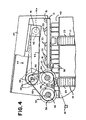
- nudger motor 41 is mounted to a deck 85 and drives pulley 42 into rotation via a shaft 41a.
- a continuous belt 87 is disposed around pulley 42 and a pulley 89 fixedly mounted to a main drive shaft 91 which itself is mounted for rotation in decks 85 and 97.
- a pulley 93 is fixedly mounted on shaft 91
- a second continuous belt 95 is disposed around pulley 93 and nudger pulleys 56, 58 such that as shaft 41a is driven by motor 41 the nudger rollers 37 are driven into rotation.
- arm 39 is mounted to be freely rotatable about shaft 91.
- Shaft 91 extends above deck 97 and has a first roller 99 fixedly mounted thereon.
- idler rollers 101, 103, and 105 are each mounted for rotation about respective shafts extending from deck 97.
- a continuous belt 107 is disposed around each of the rollers 99, 101, 103, and 105 such that as shaft 91 is driven into rotation belt 107 rotates in the same direction as the nudger rollers 37.
- the nudger rollers 37 will always extend beyond the belt 107 such that only the leaning portion of the tops of large mailpieces will contact belt 107. Moreover, the sizing of the pulleys in the drive train is such that the belt 107 is driven at a lower or the same velocity as the nudger rollers 37.
- the mail handling system includes a through-beam sensor 81 which projects a beam across opening 40 in the vicinity of nudger rollers 37.
- sensor 81 is blocked identifying their presence such that microprocessor 61 operates motor 41 to drive the nudger rollers 37. However, if sensor 81 is not blocked, the nudger rollers 37 are not driven.
Landscapes
- Engineering & Computer Science (AREA)
- Mechanical Engineering (AREA)
- Sorting Of Articles (AREA)
- Sheets, Magazines, And Separation Thereof (AREA)
- Separation, Sorting, Adjustment, Or Bending Of Sheets To Be Conveyed (AREA)
- Pile Receivers (AREA)
Claims (9)
- Fördereinrichtung für ein Posthandhabungssystem, das einen Stapel (5) von Mischpost bearbeitet, wobei die Fördereinrichtung umfasst:wobei zu Zeiten, wenn das Anwendungsmittel (37, 39) in der ersten Position (53) ist, der Stapelvorrückungsmechanismus (13) den Stapel aus Mischpost in der Richtung des Anwendungsmittels (37) bewegt, was das Anwendungsmittel veranlasst, sich von der ersten Position (53) zu der zweiten Position (55) gegen das Vorspannmittel (49) derart zu bewegen, dass sich die Stapelkraft erhöht, was eine entsprechende Erhöhung der Zuführungskraft bewirkt;Mittel (37, 39) zum Anwenden einer Zuführungskraft auf ein Führungspoststück (3a) des Stapels (5) aus Mischpost, um das Führungspoststück (3a) des Stapels (5) entlang eines Poststückzuführungspfades zuzuführen, wobei das Anwendungsmittel zwischen ersten (53) und zweiten (55) Positionen beweglich ist;Mittel (49) zum Vorspannen des Anwendungsmittels gegen eine Vorderseite des Führungspoststücks (3a), wobei dadurch eine Stapelkraft gegen den Stapel (5) aus Mischpost generiert wird; undeinen Stapelvorrückungsmechanismus (13) zum Bewegen des Stapels (5) aus Mischpost derart, dass die Vorderseite des Führungspoststücks (3a) das Anwendungsmittel (37, 39) berührt;
wobei zu Zeiten, wenn das Anwendungsmittel (37, 39) in der zweiten Position (55) ist, der Stapelvorrückungsmechanismus stoppt, den Stapel (5) aus Mischpost zu bewegen, und das Anwendungsmittel (37, 39) Poststücke kontinuierlich weg von dem Stapel (5) aus Mischpost entlang des Poststückzuführungspfades zuführt, wobei dadurch die Größe des Stapels (5) aus Mischpost kontinuierlich verringert wird, sodass das Vorspannmittel (49) das Anwendungsmittel (37, 39) von der zweiten Position (55) zu der ersten Position (53) allmählich bewegt und sich die Stapelkraft während einer Bewegung des Anwendungsmittels (37, 39) von der zweiten Position zu der ersten Position allmählich verringert;
wobei die Fördereinrichtung ferner umfasst:Mittel (63) zum Bestimmen, wenn Poststücke in dem Poststückzuführungspfad blockiert sind; undMittel (29, 66; 71, 73) zum Ausüben einer zusätzlichen Stapelkraft auf den Stapel (5) aus Mischpost als Reaktion auf eine bestimmte Blockierung. - Fördereinrichtung, wie in Anspruch 1 vorgetragen, wobei das Anwendungsmittel einen Arm (39), der zwischen den ersten und zweiten Positionen beweglich ist, eine Vielzahl von Fördereinrichtungswalzen (37), die zur Drehung an dem Arm (39) befestigt sind, und Mittel (60) zum Ansteuern der Fördereinrichtungswalzen (37) in eine Drehung inkludiert, und wobei das Vorspannmittel eine Feder (49) ist, die an einem Ende am Boden (62) und an dem anderen Ende am Arm (39) befestigt ist, wobei dadurch die Vielzahl von Fördereinrichtungswalzen (37) gegen das Führungspoststück (3a) vorgespannt werden, die Führungskraft durch die Drehung der Walzen gegen das Führungspoststück geschaffen wird.
- Fördereinrichtung, wie in Anspruch 2 vorgetragen, ferner umfassend Mittel (61) zum Steuern des Stapelvorrückungsmechanismus (13) und des Anwendungsmittels und Mittel (53, 55, 57), die mit dem Steuermittel (61) operativ verbunden sind, zum Abtasten der Position des Arms (39) und zum Vorsehen einer Angabe der abgetasteten Position zu dem Steuermittel (61) derart, dass das Steuermittel den Stapelvorrückungsmechanismus (13) betreibt und stoppt, wenn der Arm (39) in der ersten bzw. zweiten Position ist.
- Fördereinrichtung, wie in Anspruch 3 vorgetragen, wobei das Bestimmungsmittel (63) zum Blockieren in Verbindung mit dem Steuermittel (61) ist, und zu Zeiten, wenn das Bestimmungsmittel (63) bestimmt, dass Poststücke blockiert sind, das Steuermittel (61) den Stapelvorrückungsmechanismus (13) betreibt, um den Stapel aus Mischpost in der Richtung des Anwendungsmittels (37, 39) zu bewegen, bis sich der Arm (39) zu einer dritten Position (57) bewegt hat, wo die Stapelkraft, die durch die Feder (49) generiert wird, größer als die Stapelkraft ist, die durch die Feder (49) generiert wird, wenn der Arm (39) in der zweiten Position (55) ist, wobei die zusätzliche Stapelkraft die Differenz zwischen der Stapelkraft, die durch die Feder (49) generiert wird, wenn der Arm (39) in der dritten Position ist, und der Stapelkraft ist, die durch die Feder (49) generiert wird, wenn der Arm (39) in der zweiten Position ist.
- Fördereinrichtung, wie in Anspruch 1 vorgetragen, wobei das Mittel zum Ausüben einer zusätzlichen Stapelkraft inkludiert einen Solenoid (71), Mittel (61) zum Steuern einer Operation des Solenoiden und eine Feder (73), die an einem Ende mit dem Anwendungsmittel (39) und am anderen Ende mit dem Solenoid (71) verbunden ist, und wobei bei der Bestimmung durch das Bestimmungsmittel (63), dass Poststücke blockiert sind, das Steuermittel (61) den Solenoid (71) betreibt, um die Länge der Feder (73) derart zu ändern, dass die Feder die zusätzliche Stapelkraft über das Anwendungsmittel (39) vorsieht.
- Fördereinrichtung, wie in Anspruch 4 vorgetragen, ferner umfassend eine zweite Feder (66), die den Arm (39) nur zu Zeiten berührt, wenn sich der Arm (39) von der zweiten Position (55) zu der dritten Position (57) bewegt hat, wobei die zweite Feder (66) eine zweite zusätzliche Stapelkraft auf den Stapel aus Post vorsieht.
- Fördereinrichtung, wie in Anspruch 2 vorgetragen, ferner umfassend einen Encoder (74), der mit der Vielzahl von Fördereinrichtungswalzen (37) und dem Ansteuermittel (41) operativ verbunden ist, wobei der Encoder eine Angabe der Drehposition der Fördereinrichtungswalzen (37) zu dem Ansteuermittel (41) sendet, und wobei jede aus der Vielzahl von Fördereinrichtungswalzen (37) einen Schwerpunkt (72) hat, der von ihrer Drehachse verschoben ist, und das Ansteuermittel (41) eine Drehung der Fördereinrichtungswalzen (37) als Reaktion auf eine Bestimmung durch das Bestimmungsmittel, dass Poststücke blockiert sind, selektiv beschleunigt, wobei dadurch die zusätzliche Stapelkraft vorgesehen wird.
- Fördereinrichtung, wie in Anspruch 2 vorgetragen, wobei während sich der Arm (39) zwischen den ersten und zweiten Positionen bewegt, er sich um eine Armachse (51) dreht, während sich die Fördereinrichtungswalzen (37) gegen die Vorderseite des Führungspoststücks (3a) drehen, eine Reaktionskraft (F1, F2) zwischen dem Führungspoststück und den Fördereinrichtungswalzen (37) geschaffen wird, um ein Moment um die Armachse (51) zu schaffen, und die Armachse (51) bezüglich der Reaktionskraft angeordnet ist, sodass während sich die Fördereinrichtungswalzen (37) mit dem Arm (39) von der zweiten zu der ersten Position bewegen, sich das Moment erhöht, das den Arm in Richtung des Stapels von Mischpost zieht, um die Stapelkraft zu erhöhen.
- Posthandhabungssystem zum Bearbeiten eines Stapels aus Mischpost umfassend eine Fördereinrichtung gemäß einem beliebigen der Bearbeitungsansprüche.
Applications Claiming Priority (2)
| Application Number | Priority Date | Filing Date | Title |
|---|---|---|---|
| US08/943,406 US5971391A (en) | 1997-10-03 | 1997-10-03 | Nudger for a mail handling system |
| US943406 | 1997-10-03 |
Publications (2)
| Publication Number | Publication Date |
|---|---|
| EP0906880A1 EP0906880A1 (de) | 1999-04-07 |
| EP0906880B1 true EP0906880B1 (de) | 2003-07-16 |
Family
ID=25479607
Family Applications (1)
| Application Number | Title | Priority Date | Filing Date |
|---|---|---|---|
| EP98118649A Expired - Lifetime EP0906880B1 (de) | 1997-10-03 | 1998-10-02 | Fördervorrichtung für ein Posthandhabungssystem |
Country Status (4)
| Country | Link |
|---|---|
| US (1) | US5971391A (de) |
| EP (1) | EP0906880B1 (de) |
| CA (1) | CA2249482C (de) |
| DE (1) | DE69816392T2 (de) |
Families Citing this family (29)
| Publication number | Priority date | Publication date | Assignee | Title |
|---|---|---|---|---|
| US6354583B1 (en) * | 1999-01-25 | 2002-03-12 | Bell & Howell Mail And Messaging Technologies Company | Sheet feeder apparatus and method with throughput control |
| FR2797856B1 (fr) * | 1999-08-25 | 2001-09-28 | Mannesmann Dematic Postal Automation Sa | Dispositif de depilage d'objets plats avec une avance de magasin asservie a une mesure d'epaisseur des objets plats |
| US6270070B1 (en) * | 1999-12-21 | 2001-08-07 | Pitney Bowes Inc. | Apparatus and method for detecting and correcting high stack forces |
| US6217020B1 (en) | 1999-12-21 | 2001-04-17 | Pitney Bowes Inc. | Method and apparatus for detecting proper mailpiece position for feeding |
| US6260841B1 (en) * | 2000-01-20 | 2001-07-17 | Unisys Corporation | Automatic document feeder hopper flag force control |
| JP3372925B2 (ja) * | 2000-03-21 | 2003-02-04 | 日本電気株式会社 | 郵便情報入力装置とそのデータの表示方法 |
| US6988021B2 (en) | 2001-12-19 | 2006-01-17 | Pitney Bowes Inc. | Method of addressing and sorting an interoffice distribution using an incoming mail sorting apparatus |
| US20030124039A1 (en) * | 2001-12-31 | 2003-07-03 | Ryan William E. | System for sanitizing incoming mail |
| US7071437B2 (en) | 2001-12-31 | 2006-07-04 | Pitney Bowes Inc. | System for detecting the presence of harmful materials in an incoming mail stream |
| US6905661B2 (en) | 2001-12-31 | 2005-06-14 | Pitney Bowes Inc. | System for sanitizing and sorting mail |
| US6740836B2 (en) | 2001-12-31 | 2004-05-25 | Pitney Bowes Inc. | System and method for outsorting suspect mail from an incoming mail stream |
| JP4077245B2 (ja) * | 2002-05-28 | 2008-04-16 | 株式会社東芝 | 紙葉類取出装置 |
| US7165053B2 (en) * | 2002-06-13 | 2007-01-16 | Pitney Bowes Inc. | System and method for pre-feeding mailpieces, detecting the presence of harmful materials in the mailpieces and sorting the mailpieces |
| US6886419B2 (en) * | 2002-06-20 | 2005-05-03 | Pitney Bowes Inc. | Mail piece for obtaining samples of harmful materials in mail processing equipment |
| US6781078B2 (en) | 2002-06-28 | 2004-08-24 | Pitney Bowes Inc. | System and method for identifying potentially life harming mailpieces in an incoming mail stream |
| US7195236B2 (en) * | 2003-03-28 | 2007-03-27 | Northrop Grumman Corporation | Automated induction systems and methods for mail and/or other objects |
| US20060000752A1 (en) * | 2003-03-28 | 2006-01-05 | Northrop Grumman Corporation | Stack correction system and method |
| US20050077217A1 (en) * | 2003-03-28 | 2005-04-14 | Hillerich Thomas A. | Carrier for mail and/or the like thin objects |
| US20040245714A1 (en) * | 2003-05-13 | 2004-12-09 | Ryan Patrick J. | Enhanced object-feeder pre-processing system |
| US7237773B1 (en) * | 2004-05-27 | 2007-07-03 | Unisys Corporation | System for feeding and transporting documents |
| US20060099065A1 (en) * | 2004-08-27 | 2006-05-11 | Northrop Grumman Corporation | Preparation operator flex-station for carrier preparation |
| US7467792B2 (en) * | 2004-09-24 | 2008-12-23 | Northrop Grumman Corporation | Anti-toppling device for mail with retractable protrusion |
| US7404554B2 (en) * | 2005-02-22 | 2008-07-29 | Graphic Packaging International, Inc. | Method and apparatus for magazine pressure control |
| US7380783B2 (en) * | 2005-03-29 | 2008-06-03 | Lexmark International, Inc. | Apparatus providing reduction in media skew during a sheet picking operation |
| US7766171B2 (en) | 2008-02-28 | 2010-08-03 | Northrop Grumman Systems Corporation | Rigid storage tray for flat and letter mail |
| US7717418B2 (en) * | 2008-09-05 | 2010-05-18 | Kern International, Inc. | Envelope conveying and positioning apparatus and related methods |
| US7971865B2 (en) * | 2008-09-05 | 2011-07-05 | Kern International, Inc. | Inserting apparatus for discrete objects into envelopes and related methods |
| US8540235B2 (en) * | 2008-09-05 | 2013-09-24 | Peter Kern | Conveying apparatus for envelopes and related methods |
| CN202427513U (zh) * | 2011-12-21 | 2012-09-12 | 东莞福泰电子有限公司 | 一种自动进纸碎纸机 |
Citations (2)
| Publication number | Priority date | Publication date | Assignee | Title |
|---|---|---|---|---|
| US4302000A (en) * | 1978-11-29 | 1981-11-24 | Licentia Patent-Verwaltungs-G.M.B.H. | Apparatus for separating a letter stack |
| US5092574A (en) * | 1990-09-05 | 1992-03-03 | Pitney Bowes Inc. | Apparatus for feeding sheets |
Family Cites Families (9)
| Publication number | Priority date | Publication date | Assignee | Title |
|---|---|---|---|---|
| DE2309756A1 (de) * | 1973-02-27 | 1974-09-12 | Licentia Gmbh | Einrichtung zur abgabe von einzelnen briefen und aehnlichen flachen sendungen aus einem stapel |
| DE3706810C1 (de) * | 1987-03-03 | 1988-03-31 | Nixdorf Computer Ag | Regelung einer Abzugseinrichtung fuer Blattmaterial |
| US4884797A (en) * | 1987-10-16 | 1989-12-05 | Bell & Howell Company | Feeder module for use in a document forwarding system |
| US4930764A (en) * | 1988-12-28 | 1990-06-05 | Pitney Bowes Inc. | Front end feeder for mail handling machine |
| US4973037A (en) * | 1988-12-28 | 1990-11-27 | Pitney Bowes Inc. | Front end feeder for mail handling machine |
| US4955596A (en) * | 1989-01-18 | 1990-09-11 | Bell & Howell Phillipsburg Company | Method and apparatus for feeding and stacking articles |
| US5116039A (en) * | 1990-09-05 | 1992-05-26 | Pitney Bowes Inc. | Apparatus for feeding sheets from a stack thereof |
| US5074540A (en) * | 1990-11-05 | 1991-12-24 | Pitney Bowes Inc. | Document singulating apparatus |
| US5415386A (en) * | 1994-05-20 | 1995-05-16 | Pitney Bowes Inc. | Vertical feeding system for inserter |
-
1997
- 1997-10-03 US US08/943,406 patent/US5971391A/en not_active Expired - Lifetime
-
1998
- 1998-10-02 CA CA002249482A patent/CA2249482C/en not_active Expired - Fee Related
- 1998-10-02 EP EP98118649A patent/EP0906880B1/de not_active Expired - Lifetime
- 1998-10-02 DE DE69816392T patent/DE69816392T2/de not_active Expired - Lifetime
Patent Citations (2)
| Publication number | Priority date | Publication date | Assignee | Title |
|---|---|---|---|---|
| US4302000A (en) * | 1978-11-29 | 1981-11-24 | Licentia Patent-Verwaltungs-G.M.B.H. | Apparatus for separating a letter stack |
| US5092574A (en) * | 1990-09-05 | 1992-03-03 | Pitney Bowes Inc. | Apparatus for feeding sheets |
Also Published As
| Publication number | Publication date |
|---|---|
| US5971391A (en) | 1999-10-26 |
| DE69816392T2 (de) | 2004-04-15 |
| EP0906880A1 (de) | 1999-04-07 |
| DE69816392D1 (de) | 2003-08-21 |
| CA2249482A1 (en) | 1999-04-03 |
| CA2249482C (en) | 2003-12-16 |
Similar Documents
| Publication | Publication Date | Title |
|---|---|---|
| EP0906880B1 (de) | Fördervorrichtung für ein Posthandhabungssystem | |
| EP0906881B2 (de) | Vereinzelungsgerät für ein Posthandhabungssystem | |
| CA2327043C (en) | Method and apparatus for detecting proper mailpiece position and feeding | |
| US6270070B1 (en) | Apparatus and method for detecting and correcting high stack forces | |
| EP1090862B1 (de) | Ausrichtmechanismus für ein Postbearbeitungssystem | |
| US7168700B2 (en) | Sheet feeder apparatus and method with throughput control | |
| EP0926085B1 (de) | Doppeltes Gerät zur Vereinzelung von Dokumenten für ein Postbearbeitungssystem | |
| US6550764B2 (en) | Apparatus and method for controlling a document-handling machine | |
| EP0376520B2 (de) | Stapelanschlag für die Zuführvorrichtung einer Postbehandlungsmaschine | |
| US5033729A (en) | Mechanism for the handling and singulating of flat materials | |
| US5415068A (en) | Multi-function envelope feeder | |
| US4968419A (en) | Document processing system | |
| US6817608B2 (en) | Method and apparatus for stacking mailpieces in consecutive order | |
| US5257777A (en) | Belt separator for document singulation | |
| EP0819096B1 (de) | Stapelmaschine für poststücke | |
| US5409204A (en) | Singulator assembly having a buffer with a biased arm | |
| US20020140162A1 (en) | Stacker | |
| CA2368032C (en) | On-edge stacker | |
| GB2258458A (en) | Method and apparatus for aligning while changing direction of flat articles | |
| US20010035602A1 (en) | Mail piece feeder for vertically orientated mail pieces and having reversible retard rollers | |
| EP0537978B1 (de) | Verfahren und Vorrichtung zum Sortieren von abgeschnittenen blattförmigen Materialien in Stapeln | |
| AU639932B2 (en) | Single sheet picking and transport mechanism | |
| WO1993002811A1 (en) | Induction subsystem for mail sorting system |
Legal Events
| Date | Code | Title | Description |
|---|---|---|---|
| PUAI | Public reference made under article 153(3) epc to a published international application that has entered the european phase |
Free format text: ORIGINAL CODE: 0009012 |
|
| AK | Designated contracting states |
Kind code of ref document: A1 Designated state(s): DE FR GB |
|
| AX | Request for extension of the european patent |
Free format text: AL;LT;LV;MK;RO;SI |
|
| 17P | Request for examination filed |
Effective date: 19990906 |
|
| AKX | Designation fees paid |
Free format text: DE FR GB |
|
| 17Q | First examination report despatched |
Effective date: 20011129 |
|
| GRAH | Despatch of communication of intention to grant a patent |
Free format text: ORIGINAL CODE: EPIDOS IGRA |
|
| GRAH | Despatch of communication of intention to grant a patent |
Free format text: ORIGINAL CODE: EPIDOS IGRA |
|
| GRAA | (expected) grant |
Free format text: ORIGINAL CODE: 0009210 |
|
| AK | Designated contracting states |
Designated state(s): DE FR GB |
|
| REG | Reference to a national code |
Ref country code: GB Ref legal event code: FG4D |
|
| REF | Corresponds to: |
Ref document number: 69816392 Country of ref document: DE Date of ref document: 20030821 Kind code of ref document: P |
|
| ET | Fr: translation filed | ||
| PLBE | No opposition filed within time limit |
Free format text: ORIGINAL CODE: 0009261 |
|
| STAA | Information on the status of an ep patent application or granted ep patent |
Free format text: STATUS: NO OPPOSITION FILED WITHIN TIME LIMIT |
|
| 26N | No opposition filed |
Effective date: 20040419 |
|
| PGFP | Annual fee paid to national office [announced via postgrant information from national office to epo] |
Ref country code: DE Payment date: 20091028 Year of fee payment: 12 |
|
| PGFP | Annual fee paid to national office [announced via postgrant information from national office to epo] |
Ref country code: FR Payment date: 20101105 Year of fee payment: 13 |
|
| REG | Reference to a national code |
Ref country code: DE Ref legal event code: R119 Ref document number: 69816392 Country of ref document: DE Effective date: 20110502 |
|
| REG | Reference to a national code |
Ref country code: FR Ref legal event code: ST Effective date: 20120629 |
|
| PG25 | Lapsed in a contracting state [announced via postgrant information from national office to epo] |
Ref country code: FR Free format text: LAPSE BECAUSE OF NON-PAYMENT OF DUE FEES Effective date: 20111102 |
|
| PG25 | Lapsed in a contracting state [announced via postgrant information from national office to epo] |
Ref country code: DE Free format text: LAPSE BECAUSE OF NON-PAYMENT OF DUE FEES Effective date: 20110502 |
|
| PGFP | Annual fee paid to national office [announced via postgrant information from national office to epo] |
Ref country code: GB Payment date: 20161027 Year of fee payment: 19 |
|
| GBPC | Gb: european patent ceased through non-payment of renewal fee |
Effective date: 20171002 |
|
| PG25 | Lapsed in a contracting state [announced via postgrant information from national office to epo] |
Ref country code: GB Free format text: LAPSE BECAUSE OF NON-PAYMENT OF DUE FEES Effective date: 20171002 |