EP0375860B1 - Verfahren zur Korrektur von Verzahnungsfehlern - Google Patents
Verfahren zur Korrektur von Verzahnungsfehlern Download PDFInfo
- Publication number
- EP0375860B1 EP0375860B1 EP89119105A EP89119105A EP0375860B1 EP 0375860 B1 EP0375860 B1 EP 0375860B1 EP 89119105 A EP89119105 A EP 89119105A EP 89119105 A EP89119105 A EP 89119105A EP 0375860 B1 EP0375860 B1 EP 0375860B1
- Authority
- EP
- European Patent Office
- Prior art keywords
- gear
- shaft
- bore
- play
- gear wheel
- Prior art date
- Legal status (The legal status is an assumption and is not a legal conclusion. Google has not performed a legal analysis and makes no representation as to the accuracy of the status listed.)
- Expired - Lifetime
Links
- 238000000034 method Methods 0.000 title claims description 19
- 229920003023 plastic Polymers 0.000 claims abstract description 5
- 239000004033 plastic Substances 0.000 claims abstract description 5
- 238000006073 displacement reaction Methods 0.000 claims abstract description 4
- 238000012360 testing method Methods 0.000 claims abstract description 4
- 238000005096 rolling process Methods 0.000 claims description 2
- 238000009423 ventilation Methods 0.000 claims description 2
- 239000000463 material Substances 0.000 claims 3
- 239000011796 hollow space material Substances 0.000 claims 1
- 230000005540 biological transmission Effects 0.000 abstract description 3
- 238000004519 manufacturing process Methods 0.000 description 4
- 238000012546 transfer Methods 0.000 description 4
- 238000012937 correction Methods 0.000 description 3
- 150000001875 compounds Chemical class 0.000 description 2
- 230000001186 cumulative effect Effects 0.000 description 1
- 238000013016 damping Methods 0.000 description 1
- 230000007547 defect Effects 0.000 description 1
- 238000010586 diagram Methods 0.000 description 1
- 238000012545 processing Methods 0.000 description 1
- 230000001020 rhythmical effect Effects 0.000 description 1
Images
Classifications
-
- F—MECHANICAL ENGINEERING; LIGHTING; HEATING; WEAPONS; BLASTING
- F16—ENGINEERING ELEMENTS AND UNITS; GENERAL MEASURES FOR PRODUCING AND MAINTAINING EFFECTIVE FUNCTIONING OF MACHINES OR INSTALLATIONS; THERMAL INSULATION IN GENERAL
- F16H—GEARING
- F16H57/00—General details of gearing
- F16H57/0018—Shaft assemblies for gearings
- F16H57/0025—Shaft assemblies for gearings with gearing elements rigidly connected to a shaft, e.g. securing gears or pulleys by specially adapted splines, keys or methods
-
- F—MECHANICAL ENGINEERING; LIGHTING; HEATING; WEAPONS; BLASTING
- F16—ENGINEERING ELEMENTS AND UNITS; GENERAL MEASURES FOR PRODUCING AND MAINTAINING EFFECTIVE FUNCTIONING OF MACHINES OR INSTALLATIONS; THERMAL INSULATION IN GENERAL
- F16H—GEARING
- F16H57/00—General details of gearing
-
- Y—GENERAL TAGGING OF NEW TECHNOLOGICAL DEVELOPMENTS; GENERAL TAGGING OF CROSS-SECTIONAL TECHNOLOGIES SPANNING OVER SEVERAL SECTIONS OF THE IPC; TECHNICAL SUBJECTS COVERED BY FORMER USPC CROSS-REFERENCE ART COLLECTIONS [XRACs] AND DIGESTS
- Y10—TECHNICAL SUBJECTS COVERED BY FORMER USPC
- Y10T—TECHNICAL SUBJECTS COVERED BY FORMER US CLASSIFICATION
- Y10T29/00—Metal working
- Y10T29/49—Method of mechanical manufacture
- Y10T29/49462—Gear making
- Y10T29/49465—Gear mounting
-
- Y—GENERAL TAGGING OF NEW TECHNOLOGICAL DEVELOPMENTS; GENERAL TAGGING OF CROSS-SECTIONAL TECHNOLOGIES SPANNING OVER SEVERAL SECTIONS OF THE IPC; TECHNICAL SUBJECTS COVERED BY FORMER USPC CROSS-REFERENCE ART COLLECTIONS [XRACs] AND DIGESTS
- Y10—TECHNICAL SUBJECTS COVERED BY FORMER USPC
- Y10T—TECHNICAL SUBJECTS COVERED BY FORMER US CLASSIFICATION
- Y10T29/00—Metal working
- Y10T29/49—Method of mechanical manufacture
- Y10T29/49764—Method of mechanical manufacture with testing or indicating
- Y10T29/49771—Quantitative measuring or gauging
- Y10T29/49773—Quantitative measuring or gauging by radioactive tracing
-
- Y—GENERAL TAGGING OF NEW TECHNOLOGICAL DEVELOPMENTS; GENERAL TAGGING OF CROSS-SECTIONAL TECHNOLOGIES SPANNING OVER SEVERAL SECTIONS OF THE IPC; TECHNICAL SUBJECTS COVERED BY FORMER USPC CROSS-REFERENCE ART COLLECTIONS [XRACs] AND DIGESTS
- Y10—TECHNICAL SUBJECTS COVERED BY FORMER USPC
- Y10T—TECHNICAL SUBJECTS COVERED BY FORMER US CLASSIFICATION
- Y10T403/00—Joints and connections
- Y10T403/47—Molded joint
- Y10T403/473—Socket or open cup for bonding material
-
- Y—GENERAL TAGGING OF NEW TECHNOLOGICAL DEVELOPMENTS; GENERAL TAGGING OF CROSS-SECTIONAL TECHNOLOGIES SPANNING OVER SEVERAL SECTIONS OF THE IPC; TECHNICAL SUBJECTS COVERED BY FORMER USPC CROSS-REFERENCE ART COLLECTIONS [XRACs] AND DIGESTS
- Y10—TECHNICAL SUBJECTS COVERED BY FORMER USPC
- Y10T—TECHNICAL SUBJECTS COVERED BY FORMER US CLASSIFICATION
- Y10T74/00—Machine element or mechanism
- Y10T74/19—Gearing
- Y10T74/1987—Rotary bodies
- Y10T74/19893—Sectional
- Y10T74/19907—Sound deadening
Definitions
- the invention relates to a method for correcting gear errors in a gear pair with the aid of pitch circle displacement. Such a method is described in DE-A-3 726 233.
- DE-A-3 726 233 describes a method and a device for compensating rotational angle errors in gear transmissions, preferably in the drive of printing presses.
- the method and the device use the vibrations of a shaft for correction, which are detected by a differential measuring system.
- the rotation angle error of the respective shaft is determined according to amount and phase and then compensated for by a radial adjustment counteracting the rotation angle error.
- a ring gear that can be moved radially by the determined amount is arranged on the respective shaft.
- the invention is therefore based on the object of providing a method for compensating rotational angle errors which can be used in a simple manner during assembly and which produces a gear position with an exactly reproducible fit on the shaft.
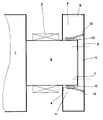
- the only figure shows an assembly diagram of a gear.
- a printing cylinder 1 or a sheet transport drum of a printing press is provided as the component to be driven.
- the pressure cylinder 1 is inserted with mounted bearings 2 and flanged gear 3 in a measuring device.
- the unit comprising the pressure cylinder 1, bearing 2 and gear 3 is supported on the bearings 2, for example on prisms, and is in this way guided parallel to a measuring axis in which a measuring gear is mounted.
- the gear 3 has a bore 4 approximately with a shaft diameter, which is not designed as a through bore.
- the bore 4 has a play 10 with respect to a shaft journal 8 on the pressure cylinder 1.
- a wall 5 remaining on the end face is provided with bores 6 (usually 4 or 6 pieces) which correspond to fastening bores 7 in the end face of the shaft journal 8.
- An auxiliary drive slowly rotates the unit mentioned.
- the measuring wheel mounted parallel to the holder of the printing cylinder 1 engages in the gear 3 to be aligned.
- Angle sensors are attached to the measuring gear and to the gear 3 itself, which are coupled to measuring devices for carrying out a single-flank rolling test.
- the two gearwheels running with each other are each held in contact on one flank and at least one full revolution is passed against one another.
- the rotary encoder it is recorded how the sequence of the two parts in engagement took place relative to one another. The deviations in the angle of rotation can thus be recorded precisely.
- the position of the gear 3 on the shaft journal 8 is changed.
- the bore 4 of the gear wheel 3 is provided with the play 10 with respect to the shaft journal 8.
- This game 10 is shown exaggerated in size in order to clarify the connection.
- the gear 3 is now shifted so that there is an optimal fit between the gear 3 and the pressure cylinder 1 in relation to all existing errors, the angular deviations being eliminated or minimized.
- the gearwheel 3 is temporarily fixed with clamping screws which connect the gearwheel 3 to the shaft journal 8 at the end.
- the final attachment takes place afterwards, however, by filling the cavity between gear 3 and shaft journal 8 with a plastic compound, for example SKC 60.
- a flat groove 11 is screwed into the bore 4 of the gear 3.
- the groove 11 should cover approximately 65% to 80% of the seat. Their depth is about 1 to 2 mm, so that the bore diameter increases by 2 to 4 mm. The remaining webs with the original diameter at the edge of the bore 4 on both sides of the groove 11 serve to roughly guide the gear 3 during the pre-assembly.
- the seat of the gear 3 on the shaft journal 8 is now absolutely free of play in the middle of the shaft-hub connection. Most of all is now but the seat of the gear 3 also optimally adapted to the geometry of the shaft journal 8 and bore 4 and fitted securely on the shaft journal 8.
- the position of this shaft-hub connection can be exactly reproduced after disassembly. None needs to be changed on the gearing to correct position errors.
- the print result is flawless after carrying out the assembly according to the method according to the invention.
- the assembly itself is carried out completely in advance, including position correction, and no longer has to be carried out with a lot of effort within the printing press.
- the alignment can also be done individually for each tooth mesh, but should be carried out on the driven gear.
- the proposed procedure can be modified in some areas. This applies both to the measuring method and to the non-positive and positive connection of the gear 3 with the shaft journal 8.
- other methods can be used, which in any case must also lead to the result that the gear is free of play in a sum tolerance of all positions. and manufacturing defects on the driven unit optimally compensating position is fixed on the shaft journal 8.
- the surface of the printing cylinder 1 can of course also be used as a comparison feature for measuring.
- the adjustment would then be carried out by optimally aligning the pitch circle of the toothing 9 with respect to the surface shape of the printing cylinder 1.
- the deviation of the toothing from its nominal position should then be minimal in the area of the sheet transfers.
Landscapes
- Engineering & Computer Science (AREA)
- General Engineering & Computer Science (AREA)
- Mechanical Engineering (AREA)
- Gears, Cams (AREA)
- Rotary Presses (AREA)
- Dental Tools And Instruments Or Auxiliary Dental Instruments (AREA)
- Radar Systems Or Details Thereof (AREA)
- Measurement Of Velocity Or Position Using Acoustic Or Ultrasonic Waves (AREA)
- Paper (AREA)
- Gear Transmission (AREA)
Priority Applications (1)
| Application Number | Priority Date | Filing Date | Title |
|---|---|---|---|
| AT89119105T ATE88799T1 (de) | 1988-12-24 | 1989-10-14 | Verfahren zur korrektur von verzahnungsfehlern. |
Applications Claiming Priority (2)
| Application Number | Priority Date | Filing Date | Title |
|---|---|---|---|
| DE3843955A DE3843955C1 (enExample) | 1988-12-24 | 1988-12-24 | |
| DE3843955 | 1988-12-24 |
Publications (2)
| Publication Number | Publication Date |
|---|---|
| EP0375860A1 EP0375860A1 (de) | 1990-07-04 |
| EP0375860B1 true EP0375860B1 (de) | 1993-04-28 |
Family
ID=6370307
Family Applications (1)
| Application Number | Title | Priority Date | Filing Date |
|---|---|---|---|
| EP89119105A Expired - Lifetime EP0375860B1 (de) | 1988-12-24 | 1989-10-14 | Verfahren zur Korrektur von Verzahnungsfehlern |
Country Status (7)
| Country | Link |
|---|---|
| US (1) | US5142783A (enExample) |
| EP (1) | EP0375860B1 (enExample) |
| JP (1) | JP2553207B2 (enExample) |
| AT (1) | ATE88799T1 (enExample) |
| BR (1) | BR8906699A (enExample) |
| DE (2) | DE3843955C1 (enExample) |
| ES (1) | ES2040961T3 (enExample) |
Cited By (1)
| Publication number | Priority date | Publication date | Assignee | Title |
|---|---|---|---|---|
| DE102007020120A1 (de) | 2007-04-28 | 2008-10-30 | Koenig & Bauer Aktiengesellschaft | Verfahren zur Bestimmung von kinematischen Abwickelfehlern an Rotationsdruckmaschinen |
Families Citing this family (6)
| Publication number | Priority date | Publication date | Assignee | Title |
|---|---|---|---|---|
| DE4317073A1 (de) * | 1993-05-21 | 1994-11-24 | Porsche Ag | Differentialgehäuse für den Achsantrieb eines Kraftfahrzeuges |
| DE19616232A1 (de) * | 1996-04-13 | 1997-10-16 | Matthias Schum | Welle mit stirnseitig lösbar befestigtem An- oder Abtriebselement |
| US20060174502A1 (en) * | 2005-02-09 | 2006-08-10 | Stephen Crane | Linear and angular measuring apparatus |
| DE102008000189B4 (de) | 2008-01-30 | 2011-02-24 | Koenig & Bauer Aktiengesellschaft | Verfahren zur Korrektur von kinematischen Abwickelfehlern an einer Rotationsdruckmaschine |
| US10612643B2 (en) | 2017-01-17 | 2020-04-07 | Forum Us, Inc. | Modular pinion shaft for reciprocating pumps |
| CN114518630B (zh) * | 2020-11-19 | 2023-09-01 | 成都极米科技股份有限公司 | 空回消除方法、装置、电子设备及计算机可读存储介质 |
Family Cites Families (9)
| Publication number | Priority date | Publication date | Assignee | Title |
|---|---|---|---|---|
| US3381548A (en) * | 1966-07-25 | 1968-05-07 | Wuelfel Eisenwerk | Planetary gearing |
| DD114017A1 (enExample) * | 1974-08-30 | 1975-07-12 | ||
| SE395524B (sv) * | 1975-12-09 | 1977-08-15 | Stal Laval Turbin Ab | Innerkuggring for planetvexel i kompoundutforande for att minska ringens styvhet |
| DE2557701C3 (de) * | 1975-12-20 | 1983-11-24 | Blümle, Rudi, 7000 Stuttgart | Verfahren zur Herstellung der Aufnahmeplatte einer Vorrichtung zum paßgenauen Aufspannen von Werkstücken |
| DD136352B1 (de) * | 1978-04-19 | 1986-07-09 | Planeta Druckmaschinenwerk Ag | Zahnradgetriebener rotationskoerper |
| JPS6313939A (ja) * | 1986-07-03 | 1988-01-21 | Takashi Takahashi | 制御用変速装置 |
| US4790971A (en) * | 1986-07-09 | 1988-12-13 | Trantek Inc. | Shuttle transfer system |
| DD256545A1 (de) * | 1987-01-23 | 1988-05-11 | Polygraph Leipzig | Verfahren und vorrichtung zum ausgleich von drehwinkelfehlern in zahnradgetrieben |
| DE3730308A1 (de) * | 1987-09-10 | 1989-03-23 | Roland Man Druckmasch | Lager fuer zylinder von druckmaschinen |
-
1988
- 1988-12-24 DE DE3843955A patent/DE3843955C1/de not_active Expired - Lifetime
-
1989
- 1989-10-14 DE DE8989119105T patent/DE58904208D1/de not_active Expired - Fee Related
- 1989-10-14 AT AT89119105T patent/ATE88799T1/de not_active IP Right Cessation
- 1989-10-14 ES ES198989119105T patent/ES2040961T3/es not_active Expired - Lifetime
- 1989-10-14 EP EP89119105A patent/EP0375860B1/de not_active Expired - Lifetime
- 1989-12-20 JP JP1328545A patent/JP2553207B2/ja not_active Expired - Fee Related
- 1989-12-22 BR BR898906699A patent/BR8906699A/pt not_active IP Right Cessation
- 1989-12-26 US US07/456,374 patent/US5142783A/en not_active Expired - Fee Related
Cited By (2)
| Publication number | Priority date | Publication date | Assignee | Title |
|---|---|---|---|---|
| DE102007020120A1 (de) | 2007-04-28 | 2008-10-30 | Koenig & Bauer Aktiengesellschaft | Verfahren zur Bestimmung von kinematischen Abwickelfehlern an Rotationsdruckmaschinen |
| DE102007020120B4 (de) * | 2007-04-28 | 2011-11-17 | Koenig & Bauer Aktiengesellschaft | Verfahren zur Bestimmung von kinematischen Abwickelfehlern an Rotationsdruckmaschinen |
Also Published As
| Publication number | Publication date |
|---|---|
| ES2040961T3 (es) | 1993-11-01 |
| DE3843955C1 (enExample) | 1990-07-12 |
| EP0375860A1 (de) | 1990-07-04 |
| US5142783A (en) | 1992-09-01 |
| ATE88799T1 (de) | 1993-05-15 |
| JPH02221755A (ja) | 1990-09-04 |
| BR8906699A (pt) | 1990-09-11 |
| JP2553207B2 (ja) | 1996-11-13 |
| DE58904208D1 (de) | 1993-06-03 |
Similar Documents
| Publication | Publication Date | Title |
|---|---|---|
| EP0621133B1 (de) | Verfahren und Anordnung für einen Elektromotor zum Antrieb eines Drehkörpers, insbesondere des druckgebenden Zylinders einer Druckmaschine | |
| EP0699524B2 (de) | Rollenrotationsoffsetdruckmaschine | |
| EP0177886B1 (de) | Flexodruckmaschine mit mehreren Farbwerken und Formzylindern | |
| EP0812682A2 (de) | Antrieb für eine Druckmaschine | |
| EP0375860B1 (de) | Verfahren zur Korrektur von Verzahnungsfehlern | |
| EP0802048A1 (de) | Drehgeber für einen Zylinder einer Druckmaschine | |
| EP0921946A1 (de) | Zylinderantrieb | |
| DE2829026C2 (de) | Vorrichtung zum Antrieb oder zur Synchronisierung von Zylindern in Offsetdruckmaschinen | |
| EP0453789A1 (de) | Bogentransporttrommel, deren Achse an einem Ende unverschiebbar und am anderen Ende translatorisch bewegbar gelagert ist | |
| DE69218447T2 (de) | Walze mit mitteln zum axialen bewegen derselben | |
| DE3781814T2 (de) | Registerkontrolle fuer kombinierte druck- und schneidmaschinen. | |
| DE2921153A1 (de) | Vorrichtung zum einstellen des seiten- und umfangsregisters in rotationsdruckmaschinen | |
| DE10304495A1 (de) | Verfahren und Anordnung für die Synchronisierung eines elektrischen Einzelantriebes | |
| EP0722831A2 (de) | Verfahren und Anordnung für einen Elektromotor zum Antrieb eines Drehkörpers, insbesondere des druckgebenden Zylinders einer Druckmaschine | |
| DE19540573C1 (de) | Vorrichtung zum Spielausgleich in Rotationsdruckmaschinen | |
| EP1759840B1 (de) | Verfahren zum reproduzierbaren Festlegen der räumlichen Winkellage mindestens eines Zylinders einer Druckmaschine. | |
| EP2072252B1 (de) | Verfahren und Anordnung zur Kompensation von regelungsbedingten Drehwinkel- Asynchronitäten | |
| DE4436584C2 (de) | Plattenzylinderlagerung | |
| DE3834429C1 (en) | Gearwheel for driving the cylinders of offset printing machines | |
| DE10234830A1 (de) | Rotationsdruckmaschine | |
| DE102023110050B3 (de) | Verfahren zur Herstellung eines Getriebestellers und ein Getriebesteller | |
| DE102019106597A1 (de) | Verfahren und Vorrichtung zur Montage von mehrstufigen drehmomentaufteilenden Getrieben | |
| DE19945783A1 (de) | Offsetrotationsbogendruckmaschine mit mehreren Druckwerken | |
| EP1392510A1 (de) | Verfahren und vorrichtung zur registerregelung | |
| DE29518046U1 (de) | Globoid-Schneckengetriebe, insbesondere für Teilgeräte und Rundtische |
Legal Events
| Date | Code | Title | Description |
|---|---|---|---|
| PUAI | Public reference made under article 153(3) epc to a published international application that has entered the european phase |
Free format text: ORIGINAL CODE: 0009012 |
|
| AK | Designated contracting states |
Kind code of ref document: A1 Designated state(s): AT BE CH DE ES FR GB IT LI NL SE |
|
| 17P | Request for examination filed |
Effective date: 19900521 |
|
| 17Q | First examination report despatched |
Effective date: 19910822 |
|
| ITF | It: translation for a ep patent filed | ||
| GRAA | (expected) grant |
Free format text: ORIGINAL CODE: 0009210 |
|
| AK | Designated contracting states |
Kind code of ref document: B1 Designated state(s): AT BE CH DE ES FR GB IT LI NL SE |
|
| REF | Corresponds to: |
Ref document number: 88799 Country of ref document: AT Date of ref document: 19930515 Kind code of ref document: T |
|
| ET | Fr: translation filed | ||
| REF | Corresponds to: |
Ref document number: 58904208 Country of ref document: DE Date of ref document: 19930603 |
|
| GBT | Gb: translation of ep patent filed (gb section 77(6)(a)/1977) |
Effective date: 19930706 |
|
| REG | Reference to a national code |
Ref country code: ES Ref legal event code: FG2A Ref document number: 2040961 Country of ref document: ES Kind code of ref document: T3 |
|
| PLBE | No opposition filed within time limit |
Free format text: ORIGINAL CODE: 0009261 |
|
| STAA | Information on the status of an ep patent application or granted ep patent |
Free format text: STATUS: NO OPPOSITION FILED WITHIN TIME LIMIT |
|
| 26N | No opposition filed | ||
| EAL | Se: european patent in force in sweden |
Ref document number: 89119105.8 |
|
| PGFP | Annual fee paid to national office [announced via postgrant information from national office to epo] |
Ref country code: NL Payment date: 19970919 Year of fee payment: 9 |
|
| PGFP | Annual fee paid to national office [announced via postgrant information from national office to epo] |
Ref country code: BE Payment date: 19971010 Year of fee payment: 9 |
|
| PGFP | Annual fee paid to national office [announced via postgrant information from national office to epo] |
Ref country code: ES Payment date: 19971021 Year of fee payment: 9 |
|
| PG25 | Lapsed in a contracting state [announced via postgrant information from national office to epo] |
Ref country code: ES Free format text: LAPSE BECAUSE OF EXPIRATION OF PROTECTION Effective date: 19981015 |
|
| PG25 | Lapsed in a contracting state [announced via postgrant information from national office to epo] |
Ref country code: BE Free format text: LAPSE BECAUSE OF NON-PAYMENT OF DUE FEES Effective date: 19981031 |
|
| BERE | Be: lapsed |
Owner name: M.A.N.-ROLAND DRUCKMASCHINEN A.G. Effective date: 19981031 |
|
| PG25 | Lapsed in a contracting state [announced via postgrant information from national office to epo] |
Ref country code: NL Free format text: LAPSE BECAUSE OF NON-PAYMENT OF DUE FEES Effective date: 19990501 |
|
| NLV4 | Nl: lapsed or anulled due to non-payment of the annual fee |
Effective date: 19990501 |
|
| PGFP | Annual fee paid to national office [announced via postgrant information from national office to epo] |
Ref country code: CH Payment date: 20000921 Year of fee payment: 12 |
|
| PGFP | Annual fee paid to national office [announced via postgrant information from national office to epo] |
Ref country code: SE Payment date: 20001002 Year of fee payment: 12 |
|
| REG | Reference to a national code |
Ref country code: ES Ref legal event code: FD2A Effective date: 20010201 |
|
| PGFP | Annual fee paid to national office [announced via postgrant information from national office to epo] |
Ref country code: AT Payment date: 20010925 Year of fee payment: 13 |
|
| PGFP | Annual fee paid to national office [announced via postgrant information from national office to epo] |
Ref country code: FR Payment date: 20011011 Year of fee payment: 13 |
|
| PG25 | Lapsed in a contracting state [announced via postgrant information from national office to epo] |
Ref country code: SE Free format text: LAPSE BECAUSE OF NON-PAYMENT OF DUE FEES Effective date: 20011015 |
|
| PG25 | Lapsed in a contracting state [announced via postgrant information from national office to epo] |
Ref country code: LI Free format text: LAPSE BECAUSE OF NON-PAYMENT OF DUE FEES Effective date: 20011031 Ref country code: CH Free format text: LAPSE BECAUSE OF NON-PAYMENT OF DUE FEES Effective date: 20011031 |
|
| REG | Reference to a national code |
Ref country code: GB Ref legal event code: IF02 |
|
| EUG | Se: european patent has lapsed |
Ref document number: 89119105.8 |
|
| REG | Reference to a national code |
Ref country code: CH Ref legal event code: PL |
|
| PGFP | Annual fee paid to national office [announced via postgrant information from national office to epo] |
Ref country code: GB Payment date: 20020925 Year of fee payment: 14 |
|
| PG25 | Lapsed in a contracting state [announced via postgrant information from national office to epo] |
Ref country code: AT Free format text: LAPSE BECAUSE OF NON-PAYMENT OF DUE FEES Effective date: 20021014 |
|
| PG25 | Lapsed in a contracting state [announced via postgrant information from national office to epo] |
Ref country code: FR Free format text: LAPSE BECAUSE OF NON-PAYMENT OF DUE FEES Effective date: 20030630 |
|
| REG | Reference to a national code |
Ref country code: FR Ref legal event code: ST |
|
| PG25 | Lapsed in a contracting state [announced via postgrant information from national office to epo] |
Ref country code: GB Free format text: LAPSE BECAUSE OF NON-PAYMENT OF DUE FEES Effective date: 20031014 |
|
| GBPC | Gb: european patent ceased through non-payment of renewal fee |
Effective date: 20031014 |
|
| PG25 | Lapsed in a contracting state [announced via postgrant information from national office to epo] |
Ref country code: IT Free format text: LAPSE BECAUSE OF NON-PAYMENT OF DUE FEES;WARNING: LAPSES OF ITALIAN PATENTS WITH EFFECTIVE DATE BEFORE 2007 MAY HAVE OCCURRED AT ANY TIME BEFORE 2007. THE CORRECT EFFECTIVE DATE MAY BE DIFFERENT FROM THE ONE RECORDED. Effective date: 20051014 |
|
| PGFP | Annual fee paid to national office [announced via postgrant information from national office to epo] |
Ref country code: DE Payment date: 20061023 Year of fee payment: 18 |
|
| PG25 | Lapsed in a contracting state [announced via postgrant information from national office to epo] |
Ref country code: DE Free format text: LAPSE BECAUSE OF NON-PAYMENT OF DUE FEES Effective date: 20080501 |