EP0375860B1 - Process for correcting gear errors - Google Patents
Process for correcting gear errors Download PDFInfo
- Publication number
- EP0375860B1 EP0375860B1 EP89119105A EP89119105A EP0375860B1 EP 0375860 B1 EP0375860 B1 EP 0375860B1 EP 89119105 A EP89119105 A EP 89119105A EP 89119105 A EP89119105 A EP 89119105A EP 0375860 B1 EP0375860 B1 EP 0375860B1
- Authority
- EP
- European Patent Office
- Prior art keywords
- gear
- shaft
- bore
- play
- gear wheel
- Prior art date
- Legal status (The legal status is an assumption and is not a legal conclusion. Google has not performed a legal analysis and makes no representation as to the accuracy of the status listed.)
- Expired - Lifetime
Links
Images
Classifications
-
- F—MECHANICAL ENGINEERING; LIGHTING; HEATING; WEAPONS; BLASTING
- F16—ENGINEERING ELEMENTS AND UNITS; GENERAL MEASURES FOR PRODUCING AND MAINTAINING EFFECTIVE FUNCTIONING OF MACHINES OR INSTALLATIONS; THERMAL INSULATION IN GENERAL
- F16H—GEARING
- F16H57/00—General details of gearing
- F16H57/0018—Shaft assemblies for gearings
- F16H57/0025—Shaft assemblies for gearings with gearing elements rigidly connected to a shaft, e.g. securing gears or pulleys by specially adapted splines, keys or methods
-
- F—MECHANICAL ENGINEERING; LIGHTING; HEATING; WEAPONS; BLASTING
- F16—ENGINEERING ELEMENTS AND UNITS; GENERAL MEASURES FOR PRODUCING AND MAINTAINING EFFECTIVE FUNCTIONING OF MACHINES OR INSTALLATIONS; THERMAL INSULATION IN GENERAL
- F16H—GEARING
- F16H57/00—General details of gearing
-
- Y—GENERAL TAGGING OF NEW TECHNOLOGICAL DEVELOPMENTS; GENERAL TAGGING OF CROSS-SECTIONAL TECHNOLOGIES SPANNING OVER SEVERAL SECTIONS OF THE IPC; TECHNICAL SUBJECTS COVERED BY FORMER USPC CROSS-REFERENCE ART COLLECTIONS [XRACs] AND DIGESTS
- Y10—TECHNICAL SUBJECTS COVERED BY FORMER USPC
- Y10T—TECHNICAL SUBJECTS COVERED BY FORMER US CLASSIFICATION
- Y10T29/00—Metal working
- Y10T29/49—Method of mechanical manufacture
- Y10T29/49462—Gear making
- Y10T29/49465—Gear mounting
-
- Y—GENERAL TAGGING OF NEW TECHNOLOGICAL DEVELOPMENTS; GENERAL TAGGING OF CROSS-SECTIONAL TECHNOLOGIES SPANNING OVER SEVERAL SECTIONS OF THE IPC; TECHNICAL SUBJECTS COVERED BY FORMER USPC CROSS-REFERENCE ART COLLECTIONS [XRACs] AND DIGESTS
- Y10—TECHNICAL SUBJECTS COVERED BY FORMER USPC
- Y10T—TECHNICAL SUBJECTS COVERED BY FORMER US CLASSIFICATION
- Y10T29/00—Metal working
- Y10T29/49—Method of mechanical manufacture
- Y10T29/49764—Method of mechanical manufacture with testing or indicating
- Y10T29/49771—Quantitative measuring or gauging
- Y10T29/49773—Quantitative measuring or gauging by radioactive tracing
-
- Y—GENERAL TAGGING OF NEW TECHNOLOGICAL DEVELOPMENTS; GENERAL TAGGING OF CROSS-SECTIONAL TECHNOLOGIES SPANNING OVER SEVERAL SECTIONS OF THE IPC; TECHNICAL SUBJECTS COVERED BY FORMER USPC CROSS-REFERENCE ART COLLECTIONS [XRACs] AND DIGESTS
- Y10—TECHNICAL SUBJECTS COVERED BY FORMER USPC
- Y10T—TECHNICAL SUBJECTS COVERED BY FORMER US CLASSIFICATION
- Y10T403/00—Joints and connections
- Y10T403/47—Molded joint
- Y10T403/473—Socket or open cup for bonding material
-
- Y—GENERAL TAGGING OF NEW TECHNOLOGICAL DEVELOPMENTS; GENERAL TAGGING OF CROSS-SECTIONAL TECHNOLOGIES SPANNING OVER SEVERAL SECTIONS OF THE IPC; TECHNICAL SUBJECTS COVERED BY FORMER USPC CROSS-REFERENCE ART COLLECTIONS [XRACs] AND DIGESTS
- Y10—TECHNICAL SUBJECTS COVERED BY FORMER USPC
- Y10T—TECHNICAL SUBJECTS COVERED BY FORMER US CLASSIFICATION
- Y10T74/00—Machine element or mechanism
- Y10T74/19—Gearing
- Y10T74/1987—Rotary bodies
- Y10T74/19893—Sectional
- Y10T74/19907—Sound deadening
Definitions
- the invention relates to a method for correcting gear errors in a gear pair with the aid of pitch circle displacement. Such a method is described in DE-A-3 726 233.
- DE-A-3 726 233 describes a method and a device for compensating rotational angle errors in gear transmissions, preferably in the drive of printing presses.
- the method and the device use the vibrations of a shaft for correction, which are detected by a differential measuring system.
- the rotation angle error of the respective shaft is determined according to amount and phase and then compensated for by a radial adjustment counteracting the rotation angle error.
- a ring gear that can be moved radially by the determined amount is arranged on the respective shaft.
- the invention is therefore based on the object of providing a method for compensating rotational angle errors which can be used in a simple manner during assembly and which produces a gear position with an exactly reproducible fit on the shaft.
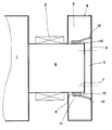
- the only figure shows an assembly diagram of a gear.
- a printing cylinder 1 or a sheet transport drum of a printing press is provided as the component to be driven.
- the pressure cylinder 1 is inserted with mounted bearings 2 and flanged gear 3 in a measuring device.
- the unit comprising the pressure cylinder 1, bearing 2 and gear 3 is supported on the bearings 2, for example on prisms, and is in this way guided parallel to a measuring axis in which a measuring gear is mounted.
- the gear 3 has a bore 4 approximately with a shaft diameter, which is not designed as a through bore.
- the bore 4 has a play 10 with respect to a shaft journal 8 on the pressure cylinder 1.
- a wall 5 remaining on the end face is provided with bores 6 (usually 4 or 6 pieces) which correspond to fastening bores 7 in the end face of the shaft journal 8.
- An auxiliary drive slowly rotates the unit mentioned.
- the measuring wheel mounted parallel to the holder of the printing cylinder 1 engages in the gear 3 to be aligned.
- Angle sensors are attached to the measuring gear and to the gear 3 itself, which are coupled to measuring devices for carrying out a single-flank rolling test.
- the two gearwheels running with each other are each held in contact on one flank and at least one full revolution is passed against one another.
- the rotary encoder it is recorded how the sequence of the two parts in engagement took place relative to one another. The deviations in the angle of rotation can thus be recorded precisely.
- the position of the gear 3 on the shaft journal 8 is changed.
- the bore 4 of the gear wheel 3 is provided with the play 10 with respect to the shaft journal 8.
- This game 10 is shown exaggerated in size in order to clarify the connection.
- the gear 3 is now shifted so that there is an optimal fit between the gear 3 and the pressure cylinder 1 in relation to all existing errors, the angular deviations being eliminated or minimized.
- the gearwheel 3 is temporarily fixed with clamping screws which connect the gearwheel 3 to the shaft journal 8 at the end.
- the final attachment takes place afterwards, however, by filling the cavity between gear 3 and shaft journal 8 with a plastic compound, for example SKC 60.
- a flat groove 11 is screwed into the bore 4 of the gear 3.
- the groove 11 should cover approximately 65% to 80% of the seat. Their depth is about 1 to 2 mm, so that the bore diameter increases by 2 to 4 mm. The remaining webs with the original diameter at the edge of the bore 4 on both sides of the groove 11 serve to roughly guide the gear 3 during the pre-assembly.
- the seat of the gear 3 on the shaft journal 8 is now absolutely free of play in the middle of the shaft-hub connection. Most of all is now but the seat of the gear 3 also optimally adapted to the geometry of the shaft journal 8 and bore 4 and fitted securely on the shaft journal 8.
- the position of this shaft-hub connection can be exactly reproduced after disassembly. None needs to be changed on the gearing to correct position errors.
- the print result is flawless after carrying out the assembly according to the method according to the invention.
- the assembly itself is carried out completely in advance, including position correction, and no longer has to be carried out with a lot of effort within the printing press.
- the alignment can also be done individually for each tooth mesh, but should be carried out on the driven gear.
- the proposed procedure can be modified in some areas. This applies both to the measuring method and to the non-positive and positive connection of the gear 3 with the shaft journal 8.
- other methods can be used, which in any case must also lead to the result that the gear is free of play in a sum tolerance of all positions. and manufacturing defects on the driven unit optimally compensating position is fixed on the shaft journal 8.
- the surface of the printing cylinder 1 can of course also be used as a comparison feature for measuring.
- the adjustment would then be carried out by optimally aligning the pitch circle of the toothing 9 with respect to the surface shape of the printing cylinder 1.
- the deviation of the toothing from its nominal position should then be minimal in the area of the sheet transfers.
Abstract
Description
Die Erfindung betrifft ein Verfahren zur Korrektur von Verzahnungsfehlern in einer Zahnradpaarung mit Hilfe von Teilkreisverschiebung. Ein solches Verfahren ist in der DE-A-3 726 233 beschrieben.The invention relates to a method for correcting gear errors in a gear pair with the aid of pitch circle displacement. Such a method is described in DE-A-3 726 233.
Die Verzahnungen normaler Stirnradgetriebe erzeugen im Betrieb Schwingungen aufgrund von Fehlern in der Verzahnung, die bei der Herstellung entstanden sind. Als Fehler treten Unrundheit der Verzahnung, Versatz der Achse und Einflüsse der Lagerung des jeweiligen Getriebeteiles auf. Die genannten Probleme wirken sich besonders stark aus, wenn z. B. in einer Druckmaschine Bogentransporttrommeln mit je zwei Übergabestellen verwendet werden. Ein an dieser Getriebeposition einzusetzendes und aufgrund der genannten Bedingung sogenannt doppeltgroßes Zahnrad wird unter vereinfachten Bedingungen für jede der beiden Übergabestellen unterschiedliche Toleranzen bzw. Fertigungsfehler in der Verzahnung aufweisen. Diese Fehler führen zu unterschiedlichen Übergabepositionen der betreffenden Bogentransporttrommel. Die Druckqualität kann dann nicht mehr gleichbleibend gewährleistet werden, da häufig ein rythmischer Versatz der Drucke von Bogen zu Bogen auftritt.The gears of normal spur gears generate vibrations during operation due to errors in the gearing that occurred during manufacture. Out-of-roundness of the gearing, misalignment of the axis and influences of the bearing of the respective gear part occur as errors. The problems mentioned have a particularly strong impact if, for. B. sheet transport drums can be used in a printing press, each with two transfer points. A gear which is to be used at this gear position and is so-called double-sized because of the condition mentioned will have different tolerances or manufacturing errors in the toothing for each of the two transfer points under simplified conditions. These errors lead to different transfer positions of the sheet transport drum concerned. The print quality can then no longer be guaranteed, since there is often a rhythmic shift in the prints from sheet to sheet.
In der DE-A-3 726 233 ist ein Verfahren und eine Vorrichtung zum Ausgleich von Drehwinkelfehlern in Zahnradgetrieben, vorzugsweise im Antrieb von Druckmaschinen, beschrieben. Das Verfahren und die Vorrichtung verwenden zur Korrektur die Schwingungen einer Welle, die durch eine Differenzmeßanlage erfaßt werden. In einer Meßwertverarbeitung wird der Drehwinkelfehler der jeweiligen Welle nach Betrag und Phase ermittelt und anschließend durch eine dem Drehwinkelfehler entgegenwirkende Radialverstellung kompensiert. Dazu ist auf der jeweiligen Welle ein um den ermittelten Betrag radialverschiebbarer Zahnkranz angeordnet.DE-A-3 726 233 describes a method and a device for compensating rotational angle errors in gear transmissions, preferably in the drive of printing presses. The method and the device use the vibrations of a shaft for correction, which are detected by a differential measuring system. In a measured value processing, the rotation angle error of the respective shaft is determined according to amount and phase and then compensated for by a radial adjustment counteracting the rotation angle error. For this purpose, a ring gear that can be moved radially by the determined amount is arranged on the respective shaft.
Sowohl das geschilderte Verfahren als auch die zugehörige Vorrichtung sind sehr kompliziert. Im Grunde werden hier alle aus dem Antriebsstrang an einer Antriebsstelle innerhalb der Druckmaschine ankommenden Schwingungen ermittelt und als Fehler an dieser einen Stelle angezeigt. Dazu ist es notwendig, daß das gesamte Getriebe zuerst komplett montiert wird. Aus diesem Grund wird ein einfacheres Verfahren zur Verzahnungskorrektur angestrebt.Both the described method and the associated device are very complicated. Basically, all vibrations arriving from the drive train at a drive point within the printing press are determined and displayed as errors at this one point. To do this, it is necessary that the entire gearbox is completely assembled first. For this reason, a simpler procedure for tooth correction is sought.
Der Erfindung liegt daher die Aufgabe zugrunde, ein Verfahren zum Ausgleich von Drehwinkelfehlern zu schaffen, das während der Montage auf einfache Weise anwendbar ist und eine Zahnradposition mit exakt reproduzierbarem Sitz auf der Welle erzeugt.The invention is therefore based on the object of providing a method for compensating rotational angle errors which can be used in a simple manner during assembly and which produces a gear position with an exactly reproducible fit on the shaft.
Diese Aufgabe wird erfindungsgemäß entsprechend den Merkmalen des Anspruchs 1 gelöst. Hierbei ist als besonderer Vorteil anzusehen, daß die Position des Zahnrades nach dem Ausrichten durch die formschlüssige Verbindung exakt festgelegt ist. Es sind keine feinfühligen Einstellvorgänge notwendig, die ein Reproduzieren dieser Position erschweren würden. Besonders vorteilhaft ist weiterhin, daß die Zahnradverbindung zur Welle auf diese Weise sehr stabil und günstig für die Schwingungsdämpfung im Getriebe ausgelegt werden kann.This object is achieved according to the features of
Die Erfindung wird im Folgenden an einem Ausführungsbeispiel näher erläutert.The invention is explained in more detail below using an exemplary embodiment.
Die einzige Figur zeigt
ein Montageschema eines Zahnrades.The only figure shows
an assembly diagram of a gear.
Als anzutreibendes Bauteil ist beispielsweise ein Druckzylinder 1 oder eine Bogentransporttrommel einer Druckmaschine vorgesehen. Der Druckzylinder 1 wird mit aufgezogenen Lagern 2 und angeflanschtem Zahnrad 3 in einer Meßvorrichtung eingelegt. Dabei stützt sich die Einheit aus Druckzylinder 1, Lager 2 und Zahnrad 3 an den Lagern 2 z.B. auf Prismen ab und wird auf diese Weise parallel zu einer Meßachse geführt, in der ein Meßzahnrad gelagert ist. Das Zahnrad 3 besitzt eine Bohrung 4 etwa mit Wellendurchmesser, die nicht als Durchgangsbohrung ausgeführt ist. Die Bohrung 4 weist ein Spiel 10 gegenüber einem Wellenzapfen 8 am Druckzylinder 1 auf. Eine stirnseitig verbleibende Wand 5 ist mit Bohrungen 6 versehen (meist 4 oder 6 Stück), die mit Befestigungsbohrungen 7 in der Stirnseite des Wellenzapfens 8 korrespondieren. Ein Hilfsantrieb versetzt die genannte Einheit langsam in Drehung. Das parallel zur Halterung des Druckzylinders 1 montierte Meßrad greift in das auszurichtende Zahnrad 3 ein. An dem Meßzahnrad und am Zahnrad 3 selbst sind Drehwinkelgeber angebracht, die mit Meßgeräten zur Durchführung einer Einflankenwälzprüfung gekoppelt sind. Hierbei werden die beiden miteinander ablaufenden Zahnräder jeweils an einer Flanke in Kontakt gehalten und wenigstens über eine volle Umdrehung gegeneinander abgewälzt. Mit Hilfe der Drehwinkelgeber wird dabei aufgezeichnet, wie der Ablauf der beiden in Eingriff stehenden Teile relativ zueinander erfolgt ist. Die Drehwinkelabweichungen können so exakt aufgezeichnet werden. In die Drehwinkelabweichung zwischen dem Meßrad und der Einheit aus Druckzylinder 1, Lager 2 und Zahnrad 3 gehen sowohl Exzentrizitäten des Wellenzapfens 8, Unrundheiten der Lager 2 als auch Fertigungsungenauigkeiten an der Verzahnung 9 selbst ein, d.h. es wird ein sogenannter Summenfehler aufgenommen.For example, a
Zum Ausgleich aller dieser Fehler wird die Lage des Zahnrades 3 auf dem Wellenzapfen 8 verändert. Zu diesem Zweck ist ja die Bohrung 4 des Zahnrades 3 gegenüber dem Wellenzapfen 8 mit dem Spiel 10 versehen. Dieses Spiel 10 ist in der Darstellung übertrieben groß eingezeichnet, um den Zusammenhang zu verdeutlichen. Das Zahnrad 3 wird nun so verschoben, daß sich in Bezug auf alle vorhandenen Fehler ein optimaler Sitz zwischen Zahnrad 3 und Druckzylinder 1 ergibt, wobei die Drehwinkelabweichungen beseitigt bzw. minimiert werden. In dieser Position wird das Zahnrad 3 vorläufig mit Klemmschrauben, die das Zahnrad 3 stirnseitig mit dem Wellenzapfen 8 verbinden, fixiert. Die endgültige Befestigung erfolgt aber erst danach, indem der Hohlraum zwischen Zahnrad 3 und Wellenzapfen 8 mit einer Kunststoffmasse z.B. SKC 60 ausgefüllt wird. Dazu ist in der Bohrung 4 des Zahnrades 3 eine flache Nut 11 eingedreht. Sie erstreckt sich mittig zum Sitz des Zahnrades 3 innerhalb der Bohrung 4. Die Nut 11 soll ca. 65% bis 80% des Sitzes abdecken. Ihre Tiefe liegt etwa bei 1 bis 2 mm, sodaß sich der Bohrungsdurchmesser hier um 2 bis 4 mm vergrößert. Die bleibenden Stege mit dem ursprünglichen Durchmesser am Rand der Bohrung 4 zu beiden Seiten der Nut 11 dienen der groben Führung des Zahnrades 3 bei der Vormontage. Eine Zufuhrbohrung 12 und eine dazu um 180 Grad versetzt angebrachte Entlüftungsbohrung 13 verbinden die Bohrung 4 im Bereich der Nut 11 mit der geschlossenen Stirnseite des Zahnrades 3. Beim Ausspritzen der Nut 11 wird die Kunststoffmasse so lange unter Druck durch die Zufuhrbohrung 12 eingebracht, bis sie an der Entlüftungsbohrung 13 wieder austritt. Die Kunststoffmasse befindet sich dann überall in der Nut 11 und wird durch den engen Spalt des Spiels 10 am Austritt nach den Stirnseiten hin gehindert. Der Sitz des Zahnrades 3 auf dem Wellenzapfen 8 ist jetzt in der Mitte der Welle-Nabe-Verbindung absolut spielfrei. Vor allen Dingen ist nun aber der Sitz des Zahnrades 3 auch der Geometrie von Wellenzapfen 8 und Bohrung 4 optimal angepaßt und sicher auf dem Wellenzapfen 8 eingepaßt. Diese Wellen-Naben-Verbindung ist in ihrer Lage exakt reproduzierbar nach einer Demontage wieder zu montieren. An der Verzahnung muß zur Korrektur von Lagefehlern nichts geändert werden. Das Druckergebnis ist nach Durchführung der Montage entsprechend dem erfindungsgemäßen Verfahren einwandfrei. Die Montage selbst wird komplett d.h. inclusive Lagekorrektur vorab durchgeführt und muß nicht mehr mit viel Aufwand innerhalb der Druckmaschine bewerkstelligt werden. Die Ausrichtung kann im Übrigen für jeden Zahneingriff einzeln, sollte dabei allerdings am jeweils angetriebenen Zahnrad vorgenommen werden.To compensate for all these errors, the position of the
Die vorgeschlagene Verfahrensweise ist in Teilbereichen abänderbar. Das betrifft sowohl das Meßverfahren, als auch die kraftschlüssige und formschlüssige Verbindung des Zahnrades 3 mit dem Wellenzapfen 8. Hierbei können andere Verfahrensweisen eingesetzt werden, die auf jeden Fall auch zu dem Ergebnis führen müssen, daß das Zahnrad spielfrei in einer die Summentoleranz aller Lage- und Fertigungsfehler an der angetriebenen Einheit optimal ausgleichenden Position auf dem Wellenzapfen 8 befestigt wird.The proposed procedure can be modified in some areas. This applies both to the measuring method and to the non-positive and positive connection of the
Zum Ausmessen kann selbstverständlich als Vergleichsmerkmal auch die Oberfläche des Druckzylinders 1 verwendet werden. Die Justierung würde dann durch optimale Ausrichtung des Teilkreises der Verzahnung 9 in Bezug auf die Oberflächenform des Druckzylinders 1 erfolgen. Insbesondere soll dann die Abweichung der Verzahnung von ihrer Sollage im Bereich der Bogenübergaben minimal sein.The surface of the
Claims (5)
- Process for correcting tooth errors in a pair of gears with the aid of a pitch circle displacement in the following steps:- first the driven gear (3) of the pair of gears is connected positively with the component (shaft (8)) to be driven, for example the impression cylinder (1) of a printing press, whereby between gear (3) and the component to be driven there is present a little radial play (10),- thereafter the turning angle errors determined by a measuring process are converted into radial deviations of the toothing,- then the driven gear (3) is radially so displaced that the radial deviation of the toothing from its ideal position is minimum,- and finally the gear (3) is connected in this corrected position positively and play free with the shaft (8), characterised in that the measuring process consists in that the gear (3) in assembled condition with a fitted bearing (2) and supported on the bearing in a measuring device is subjected to a single flank rolling test.
- Process according to Claim 1, characterised in that the gear (3) is bolted in its correct position at its end face with the shaft trunnion (8) and a hollow space about the entire periphery and the region of the play (10) is filled with hardening material.
- Process according to Claim 2, characterised in that as hardening material a plastics is used, e.g. SKC 60.
- Gear for use in a process according to Claim 2 or 3, characterised in that the gear (3) is provided with a bore (4) slightly enlarged relative to the diameter of the shaft trunnion (8) so that a play (10) is present, that in the region of the middle of the seating in the bore (4) a groove (11) is provided and that a feed bore (12) and offset by 180° thereto a ventilation bore (13) are provided for introduction of the hardening material between the end face of the gear (3) and the groove (11).
- Gear according to Claim 4, characterised in that the groove (11) takes up between 60 and 85% of the width of the seating of the gear (3) and is 1 to 2 mm deep.
Priority Applications (1)
| Application Number | Priority Date | Filing Date | Title |
|---|---|---|---|
| AT89119105T ATE88799T1 (en) | 1988-12-24 | 1989-10-14 | PROCEDURE FOR CORRECTING GEAR DEFECTS. |
Applications Claiming Priority (2)
| Application Number | Priority Date | Filing Date | Title |
|---|---|---|---|
| DE3843955A DE3843955C1 (en) | 1988-12-24 | 1988-12-24 | |
| DE3843955 | 1988-12-24 |
Publications (2)
| Publication Number | Publication Date |
|---|---|
| EP0375860A1 EP0375860A1 (en) | 1990-07-04 |
| EP0375860B1 true EP0375860B1 (en) | 1993-04-28 |
Family
ID=6370307
Family Applications (1)
| Application Number | Title | Priority Date | Filing Date |
|---|---|---|---|
| EP89119105A Expired - Lifetime EP0375860B1 (en) | 1988-12-24 | 1989-10-14 | Process for correcting gear errors |
Country Status (7)
| Country | Link |
|---|---|
| US (1) | US5142783A (en) |
| EP (1) | EP0375860B1 (en) |
| JP (1) | JP2553207B2 (en) |
| AT (1) | ATE88799T1 (en) |
| BR (1) | BR8906699A (en) |
| DE (2) | DE3843955C1 (en) |
| ES (1) | ES2040961T3 (en) |
Cited By (1)
| Publication number | Priority date | Publication date | Assignee | Title |
|---|---|---|---|---|
| DE102007020120A1 (en) | 2007-04-28 | 2008-10-30 | Koenig & Bauer Aktiengesellschaft | Method for determining kinematic operating errors in rotary printing press, involves arranging scale on lateral surface of two impression cylinders of printing element of rotary printing press |
Families Citing this family (6)
| Publication number | Priority date | Publication date | Assignee | Title |
|---|---|---|---|---|
| DE4317073A1 (en) * | 1993-05-21 | 1994-11-24 | Porsche Ag | Differential case for the final drive of a motor vehicle |
| DE19616232A1 (en) * | 1996-04-13 | 1997-10-16 | Matthias Schum | Shaft with detachable actuation element |
| US20060174502A1 (en) * | 2005-02-09 | 2006-08-10 | Stephen Crane | Linear and angular measuring apparatus |
| DE102008000189B4 (en) | 2008-01-30 | 2011-02-24 | Koenig & Bauer Aktiengesellschaft | Method for correcting kinematic unwinding errors on a rotary printing machine |
| US10612643B2 (en) | 2017-01-17 | 2020-04-07 | Forum Us, Inc. | Modular pinion shaft for reciprocating pumps |
| CN114518630B (en) * | 2020-11-19 | 2023-09-01 | 成都极米科技股份有限公司 | Null back elimination method, device, electronic equipment and computer readable storage medium |
Family Cites Families (9)
| Publication number | Priority date | Publication date | Assignee | Title |
|---|---|---|---|---|
| US3381548A (en) * | 1966-07-25 | 1968-05-07 | Wuelfel Eisenwerk | Planetary gearing |
| DD114017A1 (en) * | 1974-08-30 | 1975-07-12 | ||
| SE395524B (en) * | 1975-12-09 | 1977-08-15 | Stal Laval Turbin Ab | INNER COUPLING FOR PLANET EXCHANGE IN COMPOUND DESIGN TO REDUCE THE STIFFNESS OF THE RING |
| DE2557701C3 (en) * | 1975-12-20 | 1983-11-24 | Blümle, Rudi, 7000 Stuttgart | Process for the production of the mounting plate of a device for precisely fitting workpieces |
| DD136352B1 (en) * | 1978-04-19 | 1986-07-09 | Planeta Druckmaschinenwerk Ag | GEAR DRIVEN ROTATIONAL BODY |
| JPS6313939A (en) * | 1986-07-03 | 1988-01-21 | Takashi Takahashi | Control transmission-gear |
| US4790971A (en) * | 1986-07-09 | 1988-12-13 | Trantek Inc. | Shuttle transfer system |
| DD256545A1 (en) * | 1987-01-23 | 1988-05-11 | Polygraph Leipzig | METHOD AND DEVICE FOR COMPENSATING TURNING ANGLE ERRORS IN GEAR GEARS |
| DE3730308A1 (en) * | 1987-09-10 | 1989-03-23 | Roland Man Druckmasch | BEARING FOR CYLINDERS OF PRINTING MACHINES |
-
1988
- 1988-12-24 DE DE3843955A patent/DE3843955C1/de not_active Expired - Lifetime
-
1989
- 1989-10-14 EP EP89119105A patent/EP0375860B1/en not_active Expired - Lifetime
- 1989-10-14 ES ES198989119105T patent/ES2040961T3/en not_active Expired - Lifetime
- 1989-10-14 AT AT89119105T patent/ATE88799T1/en not_active IP Right Cessation
- 1989-10-14 DE DE8989119105T patent/DE58904208D1/en not_active Expired - Fee Related
- 1989-12-20 JP JP1328545A patent/JP2553207B2/en not_active Expired - Fee Related
- 1989-12-22 BR BR898906699A patent/BR8906699A/en not_active IP Right Cessation
- 1989-12-26 US US07/456,374 patent/US5142783A/en not_active Expired - Fee Related
Cited By (2)
| Publication number | Priority date | Publication date | Assignee | Title |
|---|---|---|---|---|
| DE102007020120A1 (en) | 2007-04-28 | 2008-10-30 | Koenig & Bauer Aktiengesellschaft | Method for determining kinematic operating errors in rotary printing press, involves arranging scale on lateral surface of two impression cylinders of printing element of rotary printing press |
| DE102007020120B4 (en) * | 2007-04-28 | 2011-11-17 | Koenig & Bauer Aktiengesellschaft | Method for determining kinematic unwinding errors on rotary printing machines |
Also Published As
| Publication number | Publication date |
|---|---|
| ATE88799T1 (en) | 1993-05-15 |
| BR8906699A (en) | 1990-09-11 |
| DE58904208D1 (en) | 1993-06-03 |
| ES2040961T3 (en) | 1993-11-01 |
| EP0375860A1 (en) | 1990-07-04 |
| JP2553207B2 (en) | 1996-11-13 |
| DE3843955C1 (en) | 1990-07-12 |
| JPH02221755A (en) | 1990-09-04 |
| US5142783A (en) | 1992-09-01 |
Similar Documents
| Publication | Publication Date | Title |
|---|---|---|
| EP0621133B1 (en) | Method and arrangement for an electric motor for driving a rotary body, in particular a printing cylinder of a printing machine | |
| EP0699524B2 (en) | Rotary web offset printing machine | |
| EP0812682B1 (en) | Drive for a printing machine | |
| EP0177886B1 (en) | Flexographic printing machine with several printing units and forme cylinders | |
| EP0375860B1 (en) | Process for correcting gear errors | |
| EP0802048A1 (en) | Rotary encoder for a cylinder of a printing machine | |
| EP0921946A1 (en) | Cylinder drive | |
| EP1759840B1 (en) | Method for reproducibly determining the spatial angular position of at least a cylinder of a printing machine. | |
| DE2829026C2 (en) | Device for driving or synchronizing cylinders in offset printing machines | |
| DE4012928C2 (en) | Sheet transport drum for skew register correction | |
| DE10304495B4 (en) | Method and arrangement for the synchronization of a single electric drive | |
| EP1104858B1 (en) | Device to ensure correct tooth engagement of two gears | |
| DE2921153A1 (en) | DEVICE FOR SETTING THE PAGE AND PERIODIC REGISTER IN ROTARY PRINTING MACHINES | |
| EP0722831A2 (en) | Method and arrangement for an electric motor for driving a rotary, in particular a printing cylinder of a printing machine | |
| DE19540573C1 (en) | Device for compensating play in rotary printing machines | |
| EP2072252B1 (en) | Method and system for compensating for regulated rotation angle asynchronicities | |
| DE4436584C2 (en) | Plate cylinder storage | |
| DE19945783B4 (en) | Offset rotary printing press with multiple printing units | |
| DE10234830A1 (en) | Sheet-fed rotary printing press has gear train which drives each form cylinder and corresponding transfer cylinder, through switchable speed-change gear mechanism | |
| DE102011089185A1 (en) | Printing unit of newspaper printing machine, has cylinder drive wheels which are set in mechanical drive connection with respect to each other over intermediate wheels in drive train which is driven by the drive motor via drive wheel | |
| DE10046375B4 (en) | Drive a printing unit | |
| DE102015118911A1 (en) | Drive for sheet-fed rotary printing machines | |
| DE102005041563A1 (en) | Sheet printing machine, has piezo unit fastened to gear wheel for deforming wheel during operation of machine and connected with speed sensor that is connected with electronic control unit | |
| DE102019106597A1 (en) | Method and device for the assembly of multi-stage torque-dividing gears | |
| WO2002083420A1 (en) | Register control method and device |
Legal Events
| Date | Code | Title | Description |
|---|---|---|---|
| PUAI | Public reference made under article 153(3) epc to a published international application that has entered the european phase |
Free format text: ORIGINAL CODE: 0009012 |
|
| AK | Designated contracting states |
Kind code of ref document: A1 Designated state(s): AT BE CH DE ES FR GB IT LI NL SE |
|
| 17P | Request for examination filed |
Effective date: 19900521 |
|
| 17Q | First examination report despatched |
Effective date: 19910822 |
|
| ITF | It: translation for a ep patent filed |
Owner name: DE DOMINICIS & MAYER S. |
|
| GRAA | (expected) grant |
Free format text: ORIGINAL CODE: 0009210 |
|
| AK | Designated contracting states |
Kind code of ref document: B1 Designated state(s): AT BE CH DE ES FR GB IT LI NL SE |
|
| REF | Corresponds to: |
Ref document number: 88799 Country of ref document: AT Date of ref document: 19930515 Kind code of ref document: T |
|
| ET | Fr: translation filed | ||
| REF | Corresponds to: |
Ref document number: 58904208 Country of ref document: DE Date of ref document: 19930603 |
|
| GBT | Gb: translation of ep patent filed (gb section 77(6)(a)/1977) |
Effective date: 19930706 |
|
| REG | Reference to a national code |
Ref country code: ES Ref legal event code: FG2A Ref document number: 2040961 Country of ref document: ES Kind code of ref document: T3 |
|
| PLBE | No opposition filed within time limit |
Free format text: ORIGINAL CODE: 0009261 |
|
| STAA | Information on the status of an ep patent application or granted ep patent |
Free format text: STATUS: NO OPPOSITION FILED WITHIN TIME LIMIT |
|
| 26N | No opposition filed | ||
| EAL | Se: european patent in force in sweden |
Ref document number: 89119105.8 |
|
| PGFP | Annual fee paid to national office [announced via postgrant information from national office to epo] |
Ref country code: NL Payment date: 19970919 Year of fee payment: 9 |
|
| PGFP | Annual fee paid to national office [announced via postgrant information from national office to epo] |
Ref country code: BE Payment date: 19971010 Year of fee payment: 9 |
|
| PGFP | Annual fee paid to national office [announced via postgrant information from national office to epo] |
Ref country code: ES Payment date: 19971021 Year of fee payment: 9 |
|
| PG25 | Lapsed in a contracting state [announced via postgrant information from national office to epo] |
Ref country code: ES Free format text: LAPSE BECAUSE OF EXPIRATION OF PROTECTION Effective date: 19981015 |
|
| PG25 | Lapsed in a contracting state [announced via postgrant information from national office to epo] |
Ref country code: BE Free format text: LAPSE BECAUSE OF NON-PAYMENT OF DUE FEES Effective date: 19981031 |
|
| BERE | Be: lapsed |
Owner name: M.A.N.-ROLAND DRUCKMASCHINEN A.G. Effective date: 19981031 |
|
| PG25 | Lapsed in a contracting state [announced via postgrant information from national office to epo] |
Ref country code: NL Free format text: LAPSE BECAUSE OF NON-PAYMENT OF DUE FEES Effective date: 19990501 |
|
| NLV4 | Nl: lapsed or anulled due to non-payment of the annual fee |
Effective date: 19990501 |
|
| PGFP | Annual fee paid to national office [announced via postgrant information from national office to epo] |
Ref country code: CH Payment date: 20000921 Year of fee payment: 12 |
|
| PGFP | Annual fee paid to national office [announced via postgrant information from national office to epo] |
Ref country code: SE Payment date: 20001002 Year of fee payment: 12 |
|
| REG | Reference to a national code |
Ref country code: ES Ref legal event code: FD2A Effective date: 20010201 |
|
| PGFP | Annual fee paid to national office [announced via postgrant information from national office to epo] |
Ref country code: AT Payment date: 20010925 Year of fee payment: 13 |
|
| PGFP | Annual fee paid to national office [announced via postgrant information from national office to epo] |
Ref country code: FR Payment date: 20011011 Year of fee payment: 13 |
|
| PG25 | Lapsed in a contracting state [announced via postgrant information from national office to epo] |
Ref country code: SE Free format text: LAPSE BECAUSE OF NON-PAYMENT OF DUE FEES Effective date: 20011015 |
|
| PG25 | Lapsed in a contracting state [announced via postgrant information from national office to epo] |
Ref country code: LI Free format text: LAPSE BECAUSE OF NON-PAYMENT OF DUE FEES Effective date: 20011031 Ref country code: CH Free format text: LAPSE BECAUSE OF NON-PAYMENT OF DUE FEES Effective date: 20011031 |
|
| REG | Reference to a national code |
Ref country code: GB Ref legal event code: IF02 |
|
| EUG | Se: european patent has lapsed |
Ref document number: 89119105.8 |
|
| REG | Reference to a national code |
Ref country code: CH Ref legal event code: PL |
|
| PGFP | Annual fee paid to national office [announced via postgrant information from national office to epo] |
Ref country code: GB Payment date: 20020925 Year of fee payment: 14 |
|
| PG25 | Lapsed in a contracting state [announced via postgrant information from national office to epo] |
Ref country code: AT Free format text: LAPSE BECAUSE OF NON-PAYMENT OF DUE FEES Effective date: 20021014 |
|
| PG25 | Lapsed in a contracting state [announced via postgrant information from national office to epo] |
Ref country code: FR Free format text: LAPSE BECAUSE OF NON-PAYMENT OF DUE FEES Effective date: 20030630 |
|
| REG | Reference to a national code |
Ref country code: FR Ref legal event code: ST |
|
| PG25 | Lapsed in a contracting state [announced via postgrant information from national office to epo] |
Ref country code: GB Free format text: LAPSE BECAUSE OF NON-PAYMENT OF DUE FEES Effective date: 20031014 |
|
| GBPC | Gb: european patent ceased through non-payment of renewal fee |
Effective date: 20031014 |
|
| PG25 | Lapsed in a contracting state [announced via postgrant information from national office to epo] |
Ref country code: IT Free format text: LAPSE BECAUSE OF NON-PAYMENT OF DUE FEES;WARNING: LAPSES OF ITALIAN PATENTS WITH EFFECTIVE DATE BEFORE 2007 MAY HAVE OCCURRED AT ANY TIME BEFORE 2007. THE CORRECT EFFECTIVE DATE MAY BE DIFFERENT FROM THE ONE RECORDED. Effective date: 20051014 |
|
| PGFP | Annual fee paid to national office [announced via postgrant information from national office to epo] |
Ref country code: DE Payment date: 20061023 Year of fee payment: 18 |
|
| PG25 | Lapsed in a contracting state [announced via postgrant information from national office to epo] |
Ref country code: DE Free format text: LAPSE BECAUSE OF NON-PAYMENT OF DUE FEES Effective date: 20080501 |