EP0375294B1 - Method of producing ceramic manifolds for thermally insulating exhaust channels - Google Patents
Method of producing ceramic manifolds for thermally insulating exhaust channels Download PDFInfo
- Publication number
- EP0375294B1 EP0375294B1 EP89313141A EP89313141A EP0375294B1 EP 0375294 B1 EP0375294 B1 EP 0375294B1 EP 89313141 A EP89313141 A EP 89313141A EP 89313141 A EP89313141 A EP 89313141A EP 0375294 B1 EP0375294 B1 EP 0375294B1
- Authority
- EP
- European Patent Office
- Prior art keywords
- ceramic
- connection
- branch pipes
- article
- manifold
- Prior art date
- Legal status (The legal status is an assumption and is not a legal conclusion. Google has not performed a legal analysis and makes no representation as to the accuracy of the status listed.)
- Expired - Lifetime
Links
Images
Classifications
-
- F—MECHANICAL ENGINEERING; LIGHTING; HEATING; WEAPONS; BLASTING
- F01—MACHINES OR ENGINES IN GENERAL; ENGINE PLANTS IN GENERAL; STEAM ENGINES
- F01N—GAS-FLOW SILENCERS OR EXHAUST APPARATUS FOR MACHINES OR ENGINES IN GENERAL; GAS-FLOW SILENCERS OR EXHAUST APPARATUS FOR INTERNAL-COMBUSTION ENGINES
- F01N13/00—Exhaust or silencing apparatus characterised by constructional features
- F01N13/16—Selection of particular materials
-
- B—PERFORMING OPERATIONS; TRANSPORTING
- B28—WORKING CEMENT, CLAY, OR STONE
- B28B—SHAPING CLAY OR OTHER CERAMIC COMPOSITIONS; SHAPING SLAG; SHAPING MIXTURES CONTAINING CEMENTITIOUS MATERIAL, e.g. PLASTER
- B28B11/00—Apparatus or processes for treating or working the shaped or preshaped articles
- B28B11/12—Apparatus or processes for treating or working the shaped or preshaped articles for removing parts of the articles by cutting
-
- F—MECHANICAL ENGINEERING; LIGHTING; HEATING; WEAPONS; BLASTING
- F01—MACHINES OR ENGINES IN GENERAL; ENGINE PLANTS IN GENERAL; STEAM ENGINES
- F01N—GAS-FLOW SILENCERS OR EXHAUST APPARATUS FOR MACHINES OR ENGINES IN GENERAL; GAS-FLOW SILENCERS OR EXHAUST APPARATUS FOR INTERNAL-COMBUSTION ENGINES
- F01N13/00—Exhaust or silencing apparatus characterised by constructional features
- F01N13/08—Other arrangements or adaptations of exhaust conduits
- F01N13/10—Other arrangements or adaptations of exhaust conduits of exhaust manifolds
- F01N13/102—Other arrangements or adaptations of exhaust conduits of exhaust manifolds having thermal insulation
-
- F—MECHANICAL ENGINEERING; LIGHTING; HEATING; WEAPONS; BLASTING
- F01—MACHINES OR ENGINES IN GENERAL; ENGINE PLANTS IN GENERAL; STEAM ENGINES
- F01N—GAS-FLOW SILENCERS OR EXHAUST APPARATUS FOR MACHINES OR ENGINES IN GENERAL; GAS-FLOW SILENCERS OR EXHAUST APPARATUS FOR INTERNAL-COMBUSTION ENGINES
- F01N13/00—Exhaust or silencing apparatus characterised by constructional features
- F01N13/18—Construction facilitating manufacture, assembly, or disassembly
-
- F—MECHANICAL ENGINEERING; LIGHTING; HEATING; WEAPONS; BLASTING
- F02—COMBUSTION ENGINES; HOT-GAS OR COMBUSTION-PRODUCT ENGINE PLANTS
- F02B—INTERNAL-COMBUSTION PISTON ENGINES; COMBUSTION ENGINES IN GENERAL
- F02B1/00—Engines characterised by fuel-air mixture compression
- F02B1/02—Engines characterised by fuel-air mixture compression with positive ignition
- F02B1/04—Engines characterised by fuel-air mixture compression with positive ignition with fuel-air mixture admission into cylinder
Definitions
- This invention relates to a method of producing ceramic manifolds having at ends plural branch pipes to be used for thermally insulating exhaust channels of gasoline engines, diesel engines and the like.
- Ceramic pipes such as port liners for thermally insulating exhaust channels or exhaust manifold liners have openings on engine side and exhaust pipe side, respectively, and are used to prevent temperature lowering of high temperature engine exhaust gases passing therethrough.
- Such ceramic pipes are generally complicated in shape.
- ceramic pipes for four valve engines increasingly used are very complicated having plural branch pipes extending from ends of the ceramic pipes.
- Such ceramic pipes have been produced with split molds by drain casting, as disclosed in EP-A-312322. Even if they are formed to exact shapes, they are likely to deform in firing after the forming process. Particularly, in the case of main ceramic pipes having plural branch pipes long extending from ends of main pipes, the plural branch pipes deform by gravity so as to change spaces between the branch pipes to make difficult cast-in bonding of the ceramic pipes in cylinder blocks.
- GB 420817 discusses the manufacture of blocks and tiles by extrusion and firing.
- a hollow block is produced by extrusion, fired, and then two tiles are produced by separating opposite lateral walls of the hollow block.
- a similar method is discussed in FR-A-141828 in which two tiles are connected by rods or ribs which have weakenings to allow separation by fracture.
- the plural branch pipes are connected by elongated connections to prevent strains which would occur in firing, thereby facilitating production of complicated ceramic pipes.
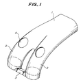
- Fig. 1 illustrates an intermediate product produced when a ceramic port liner is produced according to the invention.
- the intermediate product comprises a main ceramic pipe 1 having a plural branch pipes 2 extending from the main ceramic pipe 1 in the form of a fork. Ends of the branch pipes 2 are connected by an integral connection 3 in the form of an elongated thin plate.
- Such an intermediate product formed in the shape as above described can be integrally formed by pouring a slurry of a ceramic material as aluminum titanate into a cavity of a mold and draining excessive slurry from the mold after the poured slurry has stuck in predetermined thicknesses on inner surfaces of the mold in a conventional method called "drain casting". In the molding, it is preferable to pour and drain the slurry through valve holes 4 formed in upper portions of the branch tubes 2.
- the intermediate product shown in Fig. 1 is fired together with the connection 3 fixed thereto which serves to prevent the plural branch pipes 2 from moving toward and away from each other to maintain constant distances between the branch pipes 2 in firing.
- the ends of the branch pipes 2 including the connection 3 are removed from the main pipe 1 by cutting along phantom lines to obtain a ceramic port liner in an exact configuration.
- respective openings of the intermediate product on an engine side and an exhaust pipe side are formed integrally with closures for the openings and the closures are cut away after firing, any strains in shape of the openings are also prevented.
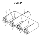
- Fig. 2 illustrates an intermediate product when an exhaust manifold liner is produced according to the invention.
- the intermediate product shown in Fig. 2 is to be used for an exhaust manifold for a four cylinder engine, four branch pipes 2 extend from a main ceramic pipe 1. These branch pipes 2 are connected together by bar connections 3 as shown. Ends of the branch pipes 2 are cut off along phantom lines in the same manner as in the first embodiment.
- the exhaust manifold liner produced in this manner is superior in dimensional accuracy, exactly keeping distances between the branch pipes 2 without any change because no strains occur in firing.
- Fig. 2 shows partial closures of the ends of the branches 2, these closures being cut away after firing.
- connection embodiments are characterized in connecting together the ends of plural branch pipes 2 by bar-shaped or plate-shaped connections 3. If the connections have too small cross-sections, deformations of the branch pipes in firing may not be completely prevented. However, excessive cross-sections of the connections will unduly restrain entire contractions or shrinkages so as to cause strains in the product. Therefore, with parts of automobile engines of normal sizes, connections having thicknesses of the order of 5 mm and widths of the order of 5-10 mm are preferred. The connections are preferably elongate, i.e. longer between the connected branch pipes than thick or wide.
- Ceramic materials to be used in the invention are not limited to a particular ceramic material.
- aluminum titanate used in the embodiments is preferable.
- a ceramic pipe made of aluminum titanate can be freely deflected owing to an elasticity of its material even the ceramic pipe is cast-in bonded in a cylinder block. Therefore, there is no risk of occurrence of cracks in the ceramic pipe due to shrinkage in cooling.
- an intermediate product including plural branch pipes having ends connected together by connections is formed by drain casting and the ends of the branch pipes are cut off after firing, thereby preventing strains which would occur in firing.
- ceramic pipes complicated in shape can be readily produced.
- This method according to the invention is suitable for producing port liners for four cylinder engines and exhaust manifold liners for multi cylinder engines. Therefore, the invention can greatly contribute to the improvement of the production of ceramic manifolds for thermally insulating exhaust channels.
Landscapes
- Engineering & Computer Science (AREA)
- Chemical & Material Sciences (AREA)
- Mechanical Engineering (AREA)
- Combustion & Propulsion (AREA)
- General Engineering & Computer Science (AREA)
- Structural Engineering (AREA)
- Ceramic Engineering (AREA)
- Compositions Of Oxide Ceramics (AREA)
- Exhaust Silencers (AREA)
- Producing Shaped Articles From Materials (AREA)
- Manufacturing Of Tubular Articles Or Embedded Moulded Articles (AREA)
Applications Claiming Priority (2)
| Application Number | Priority Date | Filing Date | Title |
|---|---|---|---|
| JP322890/88 | 1988-12-21 | ||
| JP63322890A JPH02167701A (ja) | 1988-12-21 | 1988-12-21 | 排気チャネル断熱用の多枝セラミック管の製造方法 |
Publications (3)
| Publication Number | Publication Date |
|---|---|
| EP0375294A2 EP0375294A2 (en) | 1990-06-27 |
| EP0375294A3 EP0375294A3 (en) | 1990-08-08 |
| EP0375294B1 true EP0375294B1 (en) | 1993-07-21 |
Family
ID=18148762
Family Applications (1)
| Application Number | Title | Priority Date | Filing Date |
|---|---|---|---|
| EP89313141A Expired - Lifetime EP0375294B1 (en) | 1988-12-21 | 1989-12-15 | Method of producing ceramic manifolds for thermally insulating exhaust channels |
Country Status (4)
| Country | Link |
|---|---|
| US (1) | US5013501A (enExample) |
| EP (1) | EP0375294B1 (enExample) |
| JP (1) | JPH02167701A (enExample) |
| DE (1) | DE68907704T2 (enExample) |
Families Citing this family (7)
| Publication number | Priority date | Publication date | Assignee | Title |
|---|---|---|---|---|
| US5137789A (en) * | 1990-12-03 | 1992-08-11 | Caterpillar Inc. | Composite ceramic and metal article |
| JP2578531B2 (ja) * | 1991-03-30 | 1997-02-05 | 日本碍子株式会社 | 精密中空セラミック体の製造方法 |
| JPH05149196A (ja) * | 1991-10-04 | 1993-06-15 | Ngk Insulators Ltd | セラミツクポートライナーの成形方法 |
| US5476623A (en) * | 1992-03-25 | 1995-12-19 | Ngk Insulators, Ltd. | Method of manufacturing hollow ceramic part with hole therein |
| US5298213A (en) * | 1993-01-13 | 1994-03-29 | Yan-Fei Ju | Method of making a ceramic burner head |
| FR2885385B1 (fr) * | 2005-05-04 | 2007-07-27 | Faurecia Sys Echappement | Collecteur a double coque |
| US10450937B2 (en) | 2016-12-21 | 2019-10-22 | Tenneco Automotive Operating Company Inc. | Apparatus and method of producing insulation preform with graded porosity |
Family Cites Families (6)
| Publication number | Priority date | Publication date | Assignee | Title |
|---|---|---|---|---|
| GB420817A (en) * | 1933-05-09 | 1934-12-10 | Albert Thomas Oliver Quick | Improvements relating to the manufacture of blocks, tiles and the like |
| US2914834A (en) * | 1957-04-15 | 1959-12-01 | Bendix Aviat Corp | Method of making ceramic cylinders |
| FR1418281A (fr) * | 1964-10-09 | 1965-11-19 | Ceramiques Fauchon Baudot Ets | Perfectionnements apportés aux procédés pour la fabrication d'articles tels que dalles, briques et autres |
| JPS60171945U (ja) * | 1984-04-24 | 1985-11-14 | 日本特殊陶業株式会社 | 断熱ポ−トライナ− |
| JPS6233601A (ja) * | 1985-08-06 | 1987-02-13 | 株式会社イナックス | 排泥鋳込み成形方法 |
| DE3888279T2 (de) * | 1987-10-13 | 1994-09-01 | Ngk Insulators Ltd | Verfahren zum Herstellen von keramischen Hohlkörpern. |
-
1988
- 1988-12-21 JP JP63322890A patent/JPH02167701A/ja active Granted
-
1989
- 1989-12-15 EP EP89313141A patent/EP0375294B1/en not_active Expired - Lifetime
- 1989-12-15 DE DE89313141T patent/DE68907704T2/de not_active Expired - Fee Related
- 1989-12-21 US US07/454,381 patent/US5013501A/en not_active Expired - Fee Related
Also Published As
| Publication number | Publication date |
|---|---|
| EP0375294A3 (en) | 1990-08-08 |
| DE68907704T2 (de) | 1994-01-13 |
| JPH0571365B2 (enExample) | 1993-10-07 |
| US5013501A (en) | 1991-05-07 |
| EP0375294A2 (en) | 1990-06-27 |
| DE68907704D1 (de) | 1993-08-26 |
| JPH02167701A (ja) | 1990-06-28 |
Similar Documents
| Publication | Publication Date | Title |
|---|---|---|
| EP0437302A2 (en) | Ceramic port liners | |
| EP0363844B1 (en) | A cylinder liner unit for use in an internal combustion engine | |
| US4245611A (en) | Ceramic insulated engine pistons | |
| KR100325557B1 (ko) | 얇고 평평한 제품을 연속 주조하기 위한 장치용의 세라믹 층을갖는 판과 그 제조 방법 | |
| US4693294A (en) | Apparatus for producing by the casting technique a cooling means for webs between adjacent cylinders of a cylinder block and a cylinder block produced accordingly | |
| EP0375294B1 (en) | Method of producing ceramic manifolds for thermally insulating exhaust channels | |
| EP0411785B1 (en) | Cylinder liner insert and method of making engine block therewith | |
| EP0312322B1 (en) | Processes for producing hollow ceramic articles | |
| US4705092A (en) | Manufacturing method for an integral type crankshaft bearing cap | |
| US4686943A (en) | Closed-deck cylinder block for water-cooled internal combustion engines | |
| US3478999A (en) | Refractory panel unit with hinge means and frangible portions | |
| US6173756B1 (en) | Broad side element for a slab mold | |
| US4840154A (en) | Tubular ceramic body for gas passages in cylinder head of internal combustion engine | |
| JPS6146349A (ja) | 金型 | |
| JP3220249B2 (ja) | ダイキャスト成形用金型 | |
| SU1560363A1 (ru) | Безопочна литейна форма | |
| RU98110386A (ru) | Отливка блока цилиндров двигателя внутреннего сгорания и способ ее получения | |
| JPS6027571Y2 (ja) | 連続鋳造用鋳型 | |
| US8517083B2 (en) | System, apparatus and method for manufacturing metal ingots | |
| CN212884856U (zh) | 一种单缸缸盖铸造模具 | |
| JPH0313551Y2 (enExample) | ||
| JPH10323745A (ja) | シリンダブロック鋳造法 | |
| KR20000049145A (ko) | 연속 캐스팅 몰드 | |
| JP2747696B2 (ja) | 複合材用プリフォームの製造方法 | |
| JPH0733433U (ja) | 金型のカセット式冷却ブロック |
Legal Events
| Date | Code | Title | Description |
|---|---|---|---|
| PUAI | Public reference made under article 153(3) epc to a published international application that has entered the european phase |
Free format text: ORIGINAL CODE: 0009012 |
|
| PUAL | Search report despatched |
Free format text: ORIGINAL CODE: 0009013 |
|
| AK | Designated contracting states |
Kind code of ref document: A2 Designated state(s): BE DE GB |
|
| AK | Designated contracting states |
Kind code of ref document: A3 Designated state(s): BE DE GB |
|
| 17P | Request for examination filed |
Effective date: 19901027 |
|
| 17Q | First examination report despatched |
Effective date: 19910408 |
|
| GRAA | (expected) grant |
Free format text: ORIGINAL CODE: 0009210 |
|
| AK | Designated contracting states |
Kind code of ref document: B1 Designated state(s): BE DE GB |
|
| REF | Corresponds to: |
Ref document number: 68907704 Country of ref document: DE Date of ref document: 19930826 |
|
| PLBE | No opposition filed within time limit |
Free format text: ORIGINAL CODE: 0009261 |
|
| STAA | Information on the status of an ep patent application or granted ep patent |
Free format text: STATUS: NO OPPOSITION FILED WITHIN TIME LIMIT |
|
| 26N | No opposition filed | ||
| PGFP | Annual fee paid to national office [announced via postgrant information from national office to epo] |
Ref country code: GB Payment date: 19941205 Year of fee payment: 6 |
|
| PGFP | Annual fee paid to national office [announced via postgrant information from national office to epo] |
Ref country code: DE Payment date: 19941213 Year of fee payment: 6 |
|
| PGFP | Annual fee paid to national office [announced via postgrant information from national office to epo] |
Ref country code: BE Payment date: 19941214 Year of fee payment: 6 |
|
| PG25 | Lapsed in a contracting state [announced via postgrant information from national office to epo] |
Ref country code: GB Effective date: 19951215 |
|
| PG25 | Lapsed in a contracting state [announced via postgrant information from national office to epo] |
Ref country code: BE Effective date: 19951231 |
|
| BERE | Be: lapsed |
Owner name: NGK INSULATORS LTD Effective date: 19951231 |
|
| GBPC | Gb: european patent ceased through non-payment of renewal fee |
Effective date: 19951215 |
|
| PG25 | Lapsed in a contracting state [announced via postgrant information from national office to epo] |
Ref country code: DE Effective date: 19960903 |