EP0370235A1 - Verfahren und Vorrichtung zum Verbinden von Ankerwicklungsdrähten mit den Lamellen eines Hakenkollektors - Google Patents
Verfahren und Vorrichtung zum Verbinden von Ankerwicklungsdrähten mit den Lamellen eines Hakenkollektors Download PDFInfo
- Publication number
- EP0370235A1 EP0370235A1 EP89119503A EP89119503A EP0370235A1 EP 0370235 A1 EP0370235 A1 EP 0370235A1 EP 89119503 A EP89119503 A EP 89119503A EP 89119503 A EP89119503 A EP 89119503A EP 0370235 A1 EP0370235 A1 EP 0370235A1
- Authority
- EP
- European Patent Office
- Prior art keywords
- collector
- hook
- hooks
- wires
- bending
- Prior art date
- Legal status (The legal status is an assumption and is not a legal conclusion. Google has not performed a legal analysis and makes no representation as to the accuracy of the status listed.)
- Withdrawn
Links
- 238000000034 method Methods 0.000 title claims abstract description 54
- 238000004804 winding Methods 0.000 title claims abstract description 28
- 238000009413 insulation Methods 0.000 claims abstract description 38
- 239000004922 lacquer Substances 0.000 claims abstract description 36
- 238000005452 bending Methods 0.000 claims abstract description 23
- 238000003466 welding Methods 0.000 claims abstract description 18
- 238000002604 ultrasonography Methods 0.000 claims abstract description 10
- 238000004519 manufacturing process Methods 0.000 claims abstract description 6
- 241000446313 Lamella Species 0.000 claims description 20
- 230000006378 damage Effects 0.000 claims description 15
- 230000006698 induction Effects 0.000 claims description 13
- 239000002245 particle Substances 0.000 claims description 7
- 239000007787 solid Substances 0.000 claims description 7
- 230000001680 brushing effect Effects 0.000 claims description 5
- 239000003973 paint Substances 0.000 claims description 5
- 230000001154 acute effect Effects 0.000 claims description 4
- 238000005422 blasting Methods 0.000 claims description 4
- 229910000831 Steel Inorganic materials 0.000 claims description 2
- 230000001939 inductive effect Effects 0.000 claims description 2
- 239000010959 steel Substances 0.000 claims description 2
- 239000002966 varnish Substances 0.000 abstract description 2
- 239000011248 coating agent Substances 0.000 description 4
- 238000000576 coating method Methods 0.000 description 4
- 238000007664 blowing Methods 0.000 description 2
- 210000003298 dental enamel Anatomy 0.000 description 2
- 238000010438 heat treatment Methods 0.000 description 2
- 238000010297 mechanical methods and process Methods 0.000 description 2
- 238000005096 rolling process Methods 0.000 description 2
- 238000006073 displacement reaction Methods 0.000 description 1
- 230000000694 effects Effects 0.000 description 1
- 238000003780 insertion Methods 0.000 description 1
- 230000037431 insertion Effects 0.000 description 1
- 230000005226 mechanical processes and functions Effects 0.000 description 1
- 238000007790 scraping Methods 0.000 description 1
Images



Classifications
-
- H—ELECTRICITY
- H01—ELECTRIC ELEMENTS
- H01R—ELECTRICALLY-CONDUCTIVE CONNECTIONS; STRUCTURAL ASSOCIATIONS OF A PLURALITY OF MUTUALLY-INSULATED ELECTRICAL CONNECTING ELEMENTS; COUPLING DEVICES; CURRENT COLLECTORS
- H01R39/00—Rotary current collectors, distributors or interrupters
- H01R39/02—Details for dynamo electric machines
- H01R39/32—Connections of conductor to commutator segment
-
- H—ELECTRICITY
- H02—GENERATION; CONVERSION OR DISTRIBUTION OF ELECTRIC POWER
- H02K—DYNAMO-ELECTRIC MACHINES
- H02K13/00—Structural associations of current collectors with motors or generators, e.g. brush mounting plates or connections to windings; Disposition of current collectors in motors or generators; Arrangements for improving commutation
- H02K13/04—Connections between commutator segments and windings
-
- Y—GENERAL TAGGING OF NEW TECHNOLOGICAL DEVELOPMENTS; GENERAL TAGGING OF CROSS-SECTIONAL TECHNOLOGIES SPANNING OVER SEVERAL SECTIONS OF THE IPC; TECHNICAL SUBJECTS COVERED BY FORMER USPC CROSS-REFERENCE ART COLLECTIONS [XRACs] AND DIGESTS
- Y10—TECHNICAL SUBJECTS COVERED BY FORMER USPC
- Y10T—TECHNICAL SUBJECTS COVERED BY FORMER US CLASSIFICATION
- Y10T29/00—Metal working
- Y10T29/49—Method of mechanical manufacture
- Y10T29/49002—Electrical device making
- Y10T29/49009—Dynamoelectric machine
- Y10T29/49011—Commutator or slip ring assembly
-
- Y—GENERAL TAGGING OF NEW TECHNOLOGICAL DEVELOPMENTS; GENERAL TAGGING OF CROSS-SECTIONAL TECHNOLOGIES SPANNING OVER SEVERAL SECTIONS OF THE IPC; TECHNICAL SUBJECTS COVERED BY FORMER USPC CROSS-REFERENCE ART COLLECTIONS [XRACs] AND DIGESTS
- Y10—TECHNICAL SUBJECTS COVERED BY FORMER USPC
- Y10T—TECHNICAL SUBJECTS COVERED BY FORMER US CLASSIFICATION
- Y10T29/00—Metal working
- Y10T29/49—Method of mechanical manufacture
- Y10T29/49002—Electrical device making
- Y10T29/49009—Dynamoelectric machine
- Y10T29/49012—Rotor
Definitions
- the invention relates to a method for producing an electrically conductive and mechanically strong connection of armature winding wires to the slats of a hook collector, in which the wires laid during the winding process without stripping around the hooks of the collector slats are fixed by bending the hooks and the free ends of the hooks Ultrasonic welding can be connected to the associated collector plates.
- the invention also includes devices which are particularly suitable for carrying out the method, with a sonotrode which can be moved relative to the hook collector for bending the hooks and ultrasound welding of the hook ends with the collector lamellae.
- the collector lamellae are to be rolled on a contacting surface of a sonotrode and / or vice versa, as a result of which both the enamel insulation of the armature winding wires flake off during the welding process and, at the same time, a mechanical connection between the hooks and lamellae is to be produced by ultrasonic welding .
- the desired peeling of the lacquer insulation layer does not take place uniformly and / or completely, so that this method does not lead to reproducible electrical connections on the individual lamellae of a collector, which means that it is not suitable for the mass production of collectors because of the high reject rate.
- a method has also already been proposed (DE-OS 24 16 411) in which, in order to produce an electrically conductive and mechanical connection between the lamellae of a hook commutator and armature winding wires, the insulation on the wire loops is first removed before they are placed around the hooks. The hooks are then bent and press welded to the slat ends.
- the partial removal of the paint insulation from the wire loops before attaching them to the hook is a complex work step that must be carried out for each wire loop.
- the lamella ends are alternately arranged on different levels, which further increases the cost of manufacturing such collectors.
- the present invention has for its object to provide a method by means of which good electrically conductive connections to the armature winding wires can be achieved on all slats of a hook collector without the slat ends having to be arranged in different planes to avoid short circuits.
- the object is achieved, starting from the genus described at the outset, according to the invention by a method which is characterized in that, before the hooks are bent, the lacquer insulation layer at the locations of the hooks is at least partially destroyed thermally and / or mechanically, and that the residues or Residues of the lacquer insulation layer during the bending of the hooks under the influence of ultrasound are at least partially removed by the ultrasonic vibrations from the wire surfaces intended for contact with the inner surface of the hooks before the hook ends are welded to the collector lamellae.
- the residues or residues of the lacquer insulation layer that occur during the thermal and / or mechanical destruction of the lacquer insulation layer are displaced or removed from the contact area under the action of ultrasound before the hooks are completely bent and welded at their ends to the collector lamellae. In this way, constant metallic contact surfaces between the slats and hooks on the one hand and the associated wire surfaces are achieved.
- the method is advantageously carried out in such a way that the residues or remnants of the lacquer insulation layer, insofar as they are not completely removed, when bent by means of the ultrasonic vibrations into a wire
- the inner surface of the hook and the surface of the lamellae are shifted. This results in defined zones of metallic contact between the wires, the inside surface of the hook and the lamella surface on each hook.
- the method is expediently carried out in such a way that the lacquer insulation layer is acted upon thermally and / or mechanically to at least partially destroy the lacquer insulation layer approximately in the longitudinal direction of the collector through the distances between the hook ends and the lamella surface. In this way, sufficiently large surface areas of the wires can be reliably freed from the coating insulation layer.
- the varnish insulation layer can be at least partially removed by contacting a highly heated body with the wires. But also by flaming or blowing highly heated air on the wires, there is an effective attack on the coating insulation layer. Burning off the lacquer insulation layer by means of a laser beam is also possible. Finally, it is also possible to directly inductively heat all of the wires of a collector at the locations of the hooks, as a result of which the lacquer insulation layer on all hooks is attacked simultaneously.
- the lacquer insulation layer can also be removed by brushing the wires at the desired locations.
- the process can also be carried out so that the Attack on the coating insulation layer in addition to the thermal processes described or exclusively by blasting the wires with fine solid particles. It is understood that if mechanical methods are additionally used, these are expediently brought into effect after the thermal methods.
- the action on the wires takes place with relative rotation between the thermally and / or mechanically acting means and the hook collector around the axis of the hook collector.
- the device is advantageously designed such that an inductively or electrically heatable ring is arranged concentrically to the hook collector and at a radial distance therefrom, which is parallel to the axis of the hook collector is slidably guided holder.
- the arrangement of the device is advantageously such that at least one burner or hot air nozzle or a laser head is arranged on the circumference of the collector and at a distance therefrom, the or whose beam direction forms an acute angle with the collector axis and hits the wires placed around the hooks.
- the device is advantageously designed so that a ring with a bristle or the like is arranged around the circumference of the hook collector and at a radial distance from it, which is rotatable and parallel to a shaft that rotates about the axis of the hook collector is attached to the movable holder.
- the device design for the destruction of the lacquer insulation layer by blasting the wires with fine solid particles is advantageously characterized in that at least one jet nozzle for ejecting fine solid particles is arranged at high speed on the circumference of the collector, the jet direction of which is at an acute angle with the collector axis forms and hits the wires laid around the hooks.
- an advantageous device variant provides that an induction coil is provided concentrically to the hook collector and at a radial distance from the hook, the induction coil and the hook collector being arranged axially displaceable relative to one another.
- the ability to move axially allows a relative displacement between the induction coil and the hook collector, so that after the wire loops have been heated directly by induction, the hooks for the attack of the sonotrode are exposed.
- the collector 1 shown in FIG. 1 has a multiplicity of fins 2 located at equal distances in its cylindrical circumferential surface, on each end of which a hook 3 is formed.
- the hooks 3 are initially coincidentally in an open position, as shown in FIGS. 1 to 9. The bent position enables the hook 3 to be looped around with the armature winding wires 5 when the armature 4, which is only indicated in FIG. 11, is wound.
- the lacquer insulating layer 6 located on the armature winding wires 5 is at least partially destroyed thermally and / or mechanically at the locations of the hooks 3.
- the lacquer insulation layer acts approximately in the longitudinal direction of the collector 1 through the distances, which are located between the ends of the hooks 3 and the surfaces of the slats 2.
- a ring 7 is arranged concentrically to the collector 1 and at a radial distance forming a gap to the collector circumferential surface, which ring is fastened to a holder 8 which is displaceably guided parallel to the axis of the collector 1.
- the ring 7 can by inductive z. B. heated up to red heat. If the ring 7 heated in this way is brought into contact with the armature winding wires 5 inserted into the hook 3, as is indicated in FIG. 3, the lacquer insulating layer 6 is thermally damaged at the points of contact and in the immediate vicinity thereof in such a way that it is damaged detaches from the wires in this area.
- the thermal action takes place simultaneously for all hooks 3 or the armature winding wires 5 inserted in the hooks.
- a relative rotation can be provided between the collector 1 and the ring 7, thereby simultaneously also mechanically scraping the Paint insulation layer is acted on at the points in question.
- At least one burner or hot air nozzle 9 is fixedly arranged on the circumference of the collector 1 and at a distance therefrom, from which a flame 10 or else highly heated air can be brought out, which the lacquer insulation layer 6 within the hook 3 removed from the armature winding wires 5.
- the collector 1 rotates about its axis in order to bring all the wires in the hook 3 into contact with the flame 10 or the hot air evenly.
- a laser head 11 is arranged instead of a burner or hot air nozzle, from which a laser beam 12 emerges directed onto the armature winding wires 5 inserted into the hooks 3.
- the laser head 11 is arranged in a stationary manner, while the collector 1 is provided for rotation about its axis.
- an induction coil 13 is provided concentrically to the collector 1, which has a radial distance to the hooks 3 on all sides, i.e. this does not affect.
- a relative rotation in this case does not have to be provided between induction coil 13 and collector 1, however, induction coil 13 and collector 1 must be arranged such that they can be displaced relative to one another in the axial direction, so that after the induction heating of the armature winding wires 5 located in hooks 3, hooks 3 for Sonotrode attack can be exposed.
- the lacquer insulating layer 6 is thermally damaged in such a way that a metallic contact between the hook lamellae and the wires can be brought about in the subsequent operations.
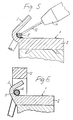
- a ring 14 is provided concentrically with the collector 1 and at a radial distance from it, or the like on its circumference with steel bristles 15. is busy.
- the ring 14 and the collector 1 are axially displaceable relative to one another and, moreover, a relative rotation can be brought about between the ring 14 and the collector 1 in order to carry out the brushing process.
- the ring 14 is attached to a holder 16.
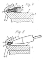
- the device shown in FIG. 8 is similar to that which has been described with reference to FIGS. 4 and 5.
- a jet nozzle 17 is arranged on the circumference of the collector 1 and at a distance from it so that the jet of fine solid particles 18 emerging from it strikes the wires 5 placed around the hooks 3.
- the device is designed so that a relative rotation between the jet nozzle 17 and the collector 1 is possible. If the jet nozzle 17 is arranged in a fixed position, the collector 1 must be rotatable about its axis.
- a plurality of jet nozzles 17 can also be provided distributed over the circumference of the collector 1.
- the hooks 3 are bent in succession on the collector 1 with simultaneous exposure to ultrasound as a second method step.
- the sonotrode of an ultrasonic welding device is used as a bending tool. To explain this process, reference is first made to FIGS. 9 and 10.
- FIG. 9 shows a sonotrode 19, on which there are, for example, two differently shaped projections 20 and 21, which are responsible for the bending shape of the hooks 3.
- a sonotrode 19 On which there are, for example, two differently shaped projections 20 and 21, which are responsible for the bending shape of the hooks 3.
- Immediately by placing one of the projections 20 or 21 on the hook 3 which is still open transmit the ultrasonic vibration of the sonotrode 19 onto the hook 3 and, with increasing bending, onto the armature winding wire 5 lying in the hook 3.
- the residues or remnants of the thermally and / or mechanically at least partially destroyed lacquer insulation layer are destroyed by the high-frequency vibrations from the electrical Contact provided surfaces of the armature winding wire 5 removed and moved into a wedge-shaped space 22 which is formed during the bending process between the wire 5, the inner surface of the hook 3 and the surface of the lamella 2.
- the bending process is essentially completed when the hook 3 strikes the surface of the collector lamella 2 with its hook
- the projection 20 or 21 of the sonotrode 19 continues to act on the hook 3, the latter is finally brought into the final shape shown in FIG. 9 by ultrasonically welding the hook end to the surface of the lamella 2.
- the armature winding wire 5 which is also somewhat deformed by the contact pressure, is wrapped over a considerable circumferential area by the hook 3 to form a reliable electrical contact.
- the second process step of bending the hook 3 under the influence of ultrasound and the third process step of welding the hook end to the collector lamella 2 follow one another directly overlapping in time.
- Fig. 10 it is shown that by appropriate arrangement and design of a projection 23 of the sonotrode 19 in the bending and welding process in addition to the wedge-shaped space 22 'yet another gap 24 between the wire 5, the inner surface of the hook 3 and the surface of the lamella 2 can be formed, in which residues or remnants of the lacquer insulation layer are also shifted during bending. In this case, too secure metallic contact between the lamella and the hook 3 on the one hand and the armature winding wire 5 on the other.
- the sonotrode 19 rotatable about its axis is provided with a cylindrical sonotrode head 25, the circumferential surface 26 of which is intended for rolling on the cylindrical circumferential surface of the collector 1.
- the circumferential surface 26 there are recesses 27 at regular intervals, which are assigned to the hook 3 of the collector 1 so that the hooks 3 are accommodated in the recesses 27 when the rolling is carried out by performing the bending and welding process described.
Landscapes
- Engineering & Computer Science (AREA)
- Power Engineering (AREA)
- Manufacture Of Motors, Generators (AREA)
- Motor Or Generator Current Collectors (AREA)
Applications Claiming Priority (2)
| Application Number | Priority Date | Filing Date | Title |
|---|---|---|---|
| DE3835818 | 1988-10-21 | ||
| DE3835818A DE3835818C3 (de) | 1988-10-21 | 1988-10-21 | Verfahren und Vorrichtung zum Verbinden von Ankerwicklungsdrähten mit den Lamellen eines Hakenkollektors |
Publications (1)
| Publication Number | Publication Date |
|---|---|
| EP0370235A1 true EP0370235A1 (de) | 1990-05-30 |
Family
ID=6365582
Family Applications (1)
| Application Number | Title | Priority Date | Filing Date |
|---|---|---|---|
| EP89119503A Withdrawn EP0370235A1 (de) | 1988-10-21 | 1989-10-20 | Verfahren und Vorrichtung zum Verbinden von Ankerwicklungsdrähten mit den Lamellen eines Hakenkollektors |
Country Status (6)
| Country | Link |
|---|---|
| US (1) | US5113574A (enExample) |
| EP (1) | EP0370235A1 (enExample) |
| JP (1) | JP2907913B2 (enExample) |
| KR (1) | KR900702604A (enExample) |
| DE (1) | DE3835818C3 (enExample) |
| WO (1) | WO1990004864A1 (enExample) |
Cited By (3)
| Publication number | Priority date | Publication date | Assignee | Title |
|---|---|---|---|---|
| EP0416704A1 (en) * | 1989-09-07 | 1991-03-13 | Koninklijke Philips Electronics N.V. | Method of connecting a conductor wire to a hook-shaped element, and rotor and/or stator for an electrical machine in which the method is used |
| ITUB20160001A1 (it) * | 2016-01-29 | 2017-07-29 | Nidec Sole Motor Corp S R L | Rotore per motore elettrico universale e procedimento per la realizzazione dello stesso |
| CN107443076A (zh) * | 2017-08-08 | 2017-12-08 | 宿松县晟鑫电器有限公司 | 一种换向器弯钩翻折研磨成型设备 |
Families Citing this family (19)
| Publication number | Priority date | Publication date | Assignee | Title |
|---|---|---|---|---|
| KR950000799B1 (ko) * | 1990-08-15 | 1995-02-02 | 가부시끼가이샤 히다찌세이사꾸쇼 | 전동기와 그 제조방법 및 장치 |
| GB9206637D0 (en) * | 1992-03-26 | 1992-05-06 | Watliff Co Ltd | Armature |
| US5772100A (en) * | 1996-03-22 | 1998-06-30 | American Technology, Inc. | Ultrasonic welder with dynamic nodal horn support |
| US5935465A (en) | 1996-11-05 | 1999-08-10 | Intermedics Inc. | Method of making implantable lead including laser wire stripping |
| DE19712712A1 (de) * | 1997-03-26 | 1998-10-01 | Bosch Gmbh Robert | Kommutator |
| EP1000457A1 (de) * | 1998-05-28 | 2000-05-17 | Robert Bosch Gmbh | Rotor für einen elektromotor und verfahren zum herstellen des rotors |
| JP3559178B2 (ja) * | 1998-10-23 | 2004-08-25 | 三菱電機株式会社 | 回転電機及びその製造方法 |
| DE10103824A1 (de) * | 2001-01-29 | 2002-09-05 | Bosch Gmbh Robert | Ständer-Anschlussteil einer elektrischen Maschine |
| FR2821498B1 (fr) * | 2001-02-28 | 2004-01-16 | Valeo Equip Electr Moteur | Procede d'assemblage de segments conducteurs d'un bobinage de rotor ou de stator de machine electrique rotative |
| JP3913998B2 (ja) * | 2001-03-01 | 2007-05-09 | マブチモーター株式会社 | 小型モータの回転子及びその製造方法 |
| JP3908588B2 (ja) * | 2001-06-06 | 2007-04-25 | マブチモーター株式会社 | 小型モータの回転子及びその製造方法 |
| DE10342158A1 (de) * | 2003-09-12 | 2005-04-07 | Robert Bosch Gmbh | Hakenkommutator |
| CN100456572C (zh) * | 2004-11-19 | 2009-01-28 | 乐金电子(天津)电器有限公司 | 单相串联电机用换向器结构 |
| JP4184395B2 (ja) * | 2006-06-30 | 2008-11-19 | Tdk株式会社 | コイル部品及びコイル部品の製造方法 |
| JP4184394B2 (ja) * | 2006-06-30 | 2008-11-19 | Tdk株式会社 | コイル部品及びコイル部品の製造方法 |
| DE202009018610U1 (de) | 2009-06-08 | 2012-10-08 | Brose Fahrzeugteile GmbH & Co. Kommanditgesellschaft, Würzburg | Rotor für einen Elektromotor |
| US9819241B2 (en) | 2010-06-14 | 2017-11-14 | Black & Decker Inc. | Stator assembly for a brushless motor in a power tool |
| CN105207040B (zh) * | 2014-03-27 | 2017-07-28 | 浙江松普换向器有限公司 | 制作钩型换向器产品的弯钩成型模具 |
| CN107231047A (zh) * | 2017-07-14 | 2017-10-03 | 广东威灵电机制造有限公司 | 转子总成及其制作方法 |
Citations (8)
| Publication number | Priority date | Publication date | Assignee | Title |
|---|---|---|---|---|
| US3421212A (en) * | 1965-02-12 | 1969-01-14 | Millers Falls Co | Method of producing commutator lead connection |
| DE2416411A1 (de) * | 1973-04-06 | 1974-10-17 | Electrolux Ab | Kommutator |
| DE2511102A1 (de) * | 1974-03-15 | 1975-09-18 | Ford Werke Ag | Verfahren zur herstellung des ankers von dynamoelektrischen maschinen |
| DE2739730A1 (de) * | 1976-09-04 | 1978-03-16 | Lucas Industries Ltd | Verfahren zur herstellung eines ankers fuer eine dynamoelektrische maschine sowie anker |
| DE3017426A1 (de) * | 1980-05-07 | 1981-11-12 | Niebuhr Mikroschweißtechnik GmbH, 8752 Goldbach | Verfahren und vorrichtung zum verbinden von ankerwicklungsdraehten mit den lamellen eines kollektors |
| DE3437744A1 (de) * | 1984-10-15 | 1986-04-24 | Schunk Ultraschalltechnik GmbH, 6301 Wettenberg | Vorrichtung zum verbinden von ankerwicklungsdraehten mit den lamellen eines kollektors |
| FR2591042A1 (fr) * | 1985-11-30 | 1987-06-05 | Licentia Gmbh | Liaison de collecteur |
| EP0280386A1 (en) * | 1987-01-21 | 1988-08-31 | Johnson Electric S.A. | Commutator connection in an electric motor |
Family Cites Families (3)
| Publication number | Priority date | Publication date | Assignee | Title |
|---|---|---|---|---|
| NL162580B (nl) * | 1970-12-17 | 1980-01-15 | Philips Nv | Werkwijze voor het ultrasoonlassen van draden op het metalen oppervlak van een drager. |
| US3781981A (en) * | 1972-02-28 | 1974-01-01 | Nippon Denko | Method for making armature-commutator assembly having armature winding of very small diameter |
| DE3513435A1 (de) * | 1985-04-15 | 1986-10-16 | Siemens AG, 1000 Berlin und 8000 München | Verfahren zum abreisssicheren kontaktieren lackisolierter draehte, insbesondere zur anwendung bei elektronischen bauteilen |
-
1988
- 1988-10-21 DE DE3835818A patent/DE3835818C3/de not_active Expired - Fee Related
-
1989
- 1989-10-19 WO PCT/DE1989/000668 patent/WO1990004864A1/de not_active Ceased
- 1989-10-19 US US07/477,930 patent/US5113574A/en not_active Expired - Fee Related
- 1989-10-19 JP JP1510761A patent/JP2907913B2/ja not_active Expired - Fee Related
- 1989-10-20 EP EP89119503A patent/EP0370235A1/de not_active Withdrawn
-
1990
- 1990-06-12 KR KR1019900701248A patent/KR900702604A/ko not_active Withdrawn
Patent Citations (8)
| Publication number | Priority date | Publication date | Assignee | Title |
|---|---|---|---|---|
| US3421212A (en) * | 1965-02-12 | 1969-01-14 | Millers Falls Co | Method of producing commutator lead connection |
| DE2416411A1 (de) * | 1973-04-06 | 1974-10-17 | Electrolux Ab | Kommutator |
| DE2511102A1 (de) * | 1974-03-15 | 1975-09-18 | Ford Werke Ag | Verfahren zur herstellung des ankers von dynamoelektrischen maschinen |
| DE2739730A1 (de) * | 1976-09-04 | 1978-03-16 | Lucas Industries Ltd | Verfahren zur herstellung eines ankers fuer eine dynamoelektrische maschine sowie anker |
| DE3017426A1 (de) * | 1980-05-07 | 1981-11-12 | Niebuhr Mikroschweißtechnik GmbH, 8752 Goldbach | Verfahren und vorrichtung zum verbinden von ankerwicklungsdraehten mit den lamellen eines kollektors |
| DE3437744A1 (de) * | 1984-10-15 | 1986-04-24 | Schunk Ultraschalltechnik GmbH, 6301 Wettenberg | Vorrichtung zum verbinden von ankerwicklungsdraehten mit den lamellen eines kollektors |
| FR2591042A1 (fr) * | 1985-11-30 | 1987-06-05 | Licentia Gmbh | Liaison de collecteur |
| EP0280386A1 (en) * | 1987-01-21 | 1988-08-31 | Johnson Electric S.A. | Commutator connection in an electric motor |
Cited By (3)
| Publication number | Priority date | Publication date | Assignee | Title |
|---|---|---|---|---|
| EP0416704A1 (en) * | 1989-09-07 | 1991-03-13 | Koninklijke Philips Electronics N.V. | Method of connecting a conductor wire to a hook-shaped element, and rotor and/or stator for an electrical machine in which the method is used |
| ITUB20160001A1 (it) * | 2016-01-29 | 2017-07-29 | Nidec Sole Motor Corp S R L | Rotore per motore elettrico universale e procedimento per la realizzazione dello stesso |
| CN107443076A (zh) * | 2017-08-08 | 2017-12-08 | 宿松县晟鑫电器有限公司 | 一种换向器弯钩翻折研磨成型设备 |
Also Published As
| Publication number | Publication date |
|---|---|
| KR900702604A (ko) | 1990-12-07 |
| JP2907913B2 (ja) | 1999-06-21 |
| DE3835818C3 (de) | 1996-02-08 |
| DE3835818C2 (enExample) | 1990-07-26 |
| WO1990004864A1 (de) | 1990-05-03 |
| US5113574A (en) | 1992-05-19 |
| JPH03502745A (ja) | 1991-06-20 |
| DE3835818A1 (de) | 1990-04-26 |
Similar Documents
| Publication | Publication Date | Title |
|---|---|---|
| DE3835818C2 (enExample) | ||
| EP0581790B1 (de) | Vorrichtung zum katalytischen entgiften von abgasen | |
| DE102018009206B3 (de) | Verbindungsbauteil zur Verbindung von elektrischen Leitern einer hairpin-Wicklung eines Stators einer Elektromaschine sowie Verfahren zur Herstellung dieser Verbindung | |
| DE102018114780A1 (de) | Vorstecknest und Verfahren zur Bildung eines Kranzes aus einer Vielzahl von U-förmigen, elektrisch leitfähigen Hairpins, um den Kranz anschließend in einem Maschinenelement einer elektrischen Maschine verbauen zu können | |
| DE2103214A1 (de) | Herstellungsverfahren einer Hohlzylinderwicklung insbesondere für Elektromotoren | |
| EP3840910A1 (de) | VERFAHREN ZUM VERSCHWEIßEN VON LEITERSTÜCKEN IN EINER KOMPONENTE EINES ELEKTROMECHANISCHEN WANDLERS SOWIE KOMPONENTE EINES ELEKTROMECHANISCHEN WANDLERS MIT VERSCHWEIßTEN LEITERSTÜCKEN | |
| DE102018106980A1 (de) | Vorrichtung und Verfahren zum Biegen von Draht für die Herstellung von Maschinenelementen elektrischer Maschinen | |
| DE102021202901A1 (de) | Vorrichtung zur Abgasnachbehandlung und Verfahren zum Herstellen dieser | |
| DE102020210575A1 (de) | Herstellungsverfahren für eine Haarnadelspule | |
| DE69111486T2 (de) | Gerät zur Montierung von einem Draht auf einer Kunststoffolie. | |
| DE102005032478A1 (de) | Verfahren zum Herstellen einer Wicklung einer elektrischen Maschine | |
| DE2649121C2 (de) | Verfahren zum Herstellen eines Kommutators für einen Elektromotor | |
| WO2020259746A1 (de) | Verfahren zur herstellung eines stators für eine elektrische maschine | |
| DE2231269B2 (de) | Verfahren zur Herstellung eines Spaltsiebes | |
| DE3017426A1 (de) | Verfahren und vorrichtung zum verbinden von ankerwicklungsdraehten mit den lamellen eines kollektors | |
| DE102015210460A1 (de) | Elektrisches Kontaktelement sowie Verfahren zur Veränderung mechanischer und/oder elektrischer Eigenschaften zumindest eines Bereichs eines solchen | |
| DE2114734C3 (de) | Verfahren und Vorrichtung zum Anlassen gehärteter Nadeln | |
| DE1057216B (de) | Stromwender mit einer in seine Isolierstoffnabe eingebetteten Drahtwendel | |
| DE1903547A1 (de) | Verfahren zum Verjuengen der Enden von flexiblen Wellen | |
| DE2509101C3 (de) | Elektrischer Rohrheizkörper mit flachovalem Querschnitt | |
| DE2615013C3 (de) | Verfahren zum Herstellen eines elektrischen Heizkörpers für gasförmige strömende Medien und Vorrichtung zur Durchführung des Verfahrens | |
| DE3942604A1 (de) | Drahtelektrodenanordnung zum funkenerosiven schneiden sowie verfahren zu deren herstellung | |
| EP4555608B1 (de) | Verfahren zur herstellung einer wellenwicklung mit abisolierten drahtenden | |
| DE102019121956A1 (de) | Imprägniervorrichtung, Imprägnieranordnung und Imprägnierverfahren mit Sperrgasströmung | |
| EP2171730B1 (de) | Elektrische spule |
Legal Events
| Date | Code | Title | Description |
|---|---|---|---|
| PUAI | Public reference made under article 153(3) epc to a published international application that has entered the european phase |
Free format text: ORIGINAL CODE: 0009012 |
|
| 17P | Request for examination filed |
Effective date: 19891020 |
|
| AK | Designated contracting states |
Kind code of ref document: A1 Designated state(s): CH DE ES FR GB IT LI SE |
|
| 17Q | First examination report despatched |
Effective date: 19931208 |
|
| RBV | Designated contracting states (corrected) |
Designated state(s): DE FR GB IT |
|
| STAA | Information on the status of an ep patent application or granted ep patent |
Free format text: STATUS: THE APPLICATION IS DEEMED TO BE WITHDRAWN |
|
| 18D | Application deemed to be withdrawn |
Effective date: 19940419 |