EP0370108B2 - Materiau de garnissage de conduites - Google Patents
Materiau de garnissage de conduites Download PDFInfo
- Publication number
- EP0370108B2 EP0370108B2 EP88908744A EP88908744A EP0370108B2 EP 0370108 B2 EP0370108 B2 EP 0370108B2 EP 88908744 A EP88908744 A EP 88908744A EP 88908744 A EP88908744 A EP 88908744A EP 0370108 B2 EP0370108 B2 EP 0370108B2
- Authority
- EP
- European Patent Office
- Prior art keywords
- yarns
- lining material
- tubular
- tubular textile
- wefts
- Prior art date
- Legal status (The legal status is an assumption and is not a legal conclusion. Google has not performed a legal analysis and makes no representation as to the accuracy of the status listed.)
- Expired - Lifetime
Links
- 239000000463 material Substances 0.000 title claims description 200
- 239000004753 textile Substances 0.000 claims description 177
- 229920000728 polyester Polymers 0.000 claims description 60
- 239000000835 fiber Substances 0.000 claims description 47
- 238000000034 method Methods 0.000 claims description 47
- 239000003365 glass fiber Substances 0.000 claims description 26
- 239000012530 fluid Substances 0.000 claims description 21
- 239000004744 fabric Substances 0.000 claims description 19
- 229920001971 elastomer Polymers 0.000 claims description 13
- 239000005060 rubber Substances 0.000 claims description 13
- 229920003002 synthetic resin Polymers 0.000 claims description 11
- 239000000057 synthetic resin Substances 0.000 claims description 11
- 239000010410 layer Substances 0.000 claims 4
- 239000012790 adhesive layer Substances 0.000 claims 2
- 239000004745 nonwoven fabric Substances 0.000 claims 2
- 239000002759 woven fabric Substances 0.000 description 48
- 229920005989 resin Polymers 0.000 description 41
- 239000011347 resin Substances 0.000 description 41
- 238000009941 weaving Methods 0.000 description 24
- 229920002994 synthetic fiber Polymers 0.000 description 23
- 239000012209 synthetic fiber Substances 0.000 description 23
- 239000003822 epoxy resin Substances 0.000 description 10
- 229920000647 polyepoxide Polymers 0.000 description 10
- 238000004026 adhesive bonding Methods 0.000 description 9
- 239000004760 aramid Substances 0.000 description 9
- 239000004677 Nylon Substances 0.000 description 8
- 229920001778 nylon Polymers 0.000 description 8
- 239000000853 adhesive Substances 0.000 description 7
- 230000001070 adhesive effect Effects 0.000 description 7
- 229920001169 thermoplastic Polymers 0.000 description 7
- 239000004416 thermosoftening plastic Substances 0.000 description 7
- 229920000049 Carbon (fiber) Polymers 0.000 description 6
- 229920003235 aromatic polyamide Polymers 0.000 description 6
- 239000004917 carbon fiber Substances 0.000 description 6
- -1 polyethylene Polymers 0.000 description 6
- 238000005452 bending Methods 0.000 description 5
- 238000010276 construction Methods 0.000 description 5
- 238000010438 heat treatment Methods 0.000 description 5
- 239000011159 matrix material Substances 0.000 description 5
- 229920001707 polybutylene terephthalate Polymers 0.000 description 5
- 230000000052 comparative effect Effects 0.000 description 4
- 239000002131 composite material Substances 0.000 description 4
- 229920002239 polyacrylonitrile Polymers 0.000 description 4
- 229920006337 unsaturated polyester resin Polymers 0.000 description 4
- XLYOFNOQVPJJNP-UHFFFAOYSA-N water Substances O XLYOFNOQVPJJNP-UHFFFAOYSA-N 0.000 description 4
- 229920002430 Fibre-reinforced plastic Polymers 0.000 description 3
- 229920006231 aramid fiber Polymers 0.000 description 3
- 230000015572 biosynthetic process Effects 0.000 description 3
- 238000002788 crimping Methods 0.000 description 3
- 239000011151 fibre-reinforced plastic Substances 0.000 description 3
- 229920002635 polyurethane Polymers 0.000 description 3
- 239000004814 polyurethane Substances 0.000 description 3
- 238000009877 rendering Methods 0.000 description 3
- 239000000126 substance Substances 0.000 description 3
- 229920000914 Metallic fiber Polymers 0.000 description 2
- 239000004433 Thermoplastic polyurethane Substances 0.000 description 2
- 125000003118 aryl group Chemical group 0.000 description 2
- 230000005540 biological transmission Effects 0.000 description 2
- 230000015556 catabolic process Effects 0.000 description 2
- 238000012423 maintenance Methods 0.000 description 2
- 229920000098 polyolefin Polymers 0.000 description 2
- 238000003825 pressing Methods 0.000 description 2
- 230000002787 reinforcement Effects 0.000 description 2
- 239000010865 sewage Substances 0.000 description 2
- 229920002803 thermoplastic polyurethane Polymers 0.000 description 2
- 230000037303 wrinkles Effects 0.000 description 2
- 239000004952 Polyamide Substances 0.000 description 1
- 239000004698 Polyethylene Substances 0.000 description 1
- BLRPTPMANUNPDV-UHFFFAOYSA-N Silane Chemical compound [SiH4] BLRPTPMANUNPDV-UHFFFAOYSA-N 0.000 description 1
- 239000002253 acid Substances 0.000 description 1
- 238000003763 carbonization Methods 0.000 description 1
- 239000003795 chemical substances by application Substances 0.000 description 1
- 230000008878 coupling Effects 0.000 description 1
- 238000010168 coupling process Methods 0.000 description 1
- 238000005859 coupling reaction Methods 0.000 description 1
- 238000005336 cracking Methods 0.000 description 1
- 230000001419 dependent effect Effects 0.000 description 1
- 238000001125 extrusion Methods 0.000 description 1
- 239000011521 glass Substances 0.000 description 1
- 229920006253 high performance fiber Polymers 0.000 description 1
- 238000005470 impregnation Methods 0.000 description 1
- 238000005304 joining Methods 0.000 description 1
- 230000014759 maintenance of location Effects 0.000 description 1
- 238000004519 manufacturing process Methods 0.000 description 1
- 238000002074 melt spinning Methods 0.000 description 1
- 230000002093 peripheral effect Effects 0.000 description 1
- 239000003208 petroleum Substances 0.000 description 1
- 229920002647 polyamide Polymers 0.000 description 1
- 229920000573 polyethylene Polymers 0.000 description 1
- 238000006116 polymerization reaction Methods 0.000 description 1
- 125000002924 primary amino group Chemical group [H]N([H])* 0.000 description 1
- 239000002994 raw material Substances 0.000 description 1
- 229910000077 silane Inorganic materials 0.000 description 1
Images


Classifications
-
- B—PERFORMING OPERATIONS; TRANSPORTING
- B32—LAYERED PRODUCTS
- B32B—LAYERED PRODUCTS, i.e. PRODUCTS BUILT-UP OF STRATA OF FLAT OR NON-FLAT, e.g. CELLULAR OR HONEYCOMB, FORM
- B32B1/00—Layered products having a general shape other than plane
- B32B1/08—Tubular products
-
- B—PERFORMING OPERATIONS; TRANSPORTING
- B32—LAYERED PRODUCTS
- B32B—LAYERED PRODUCTS, i.e. PRODUCTS BUILT-UP OF STRATA OF FLAT OR NON-FLAT, e.g. CELLULAR OR HONEYCOMB, FORM
- B32B25/00—Layered products comprising a layer of natural or synthetic rubber
- B32B25/10—Layered products comprising a layer of natural or synthetic rubber next to a fibrous or filamentary layer
-
- B—PERFORMING OPERATIONS; TRANSPORTING
- B32—LAYERED PRODUCTS
- B32B—LAYERED PRODUCTS, i.e. PRODUCTS BUILT-UP OF STRATA OF FLAT OR NON-FLAT, e.g. CELLULAR OR HONEYCOMB, FORM
- B32B27/00—Layered products comprising a layer of synthetic resin
- B32B27/06—Layered products comprising a layer of synthetic resin as the main or only constituent of a layer, which is next to another layer of the same or of a different material
- B32B27/10—Layered products comprising a layer of synthetic resin as the main or only constituent of a layer, which is next to another layer of the same or of a different material of paper or cardboard
-
- B—PERFORMING OPERATIONS; TRANSPORTING
- B32—LAYERED PRODUCTS
- B32B—LAYERED PRODUCTS, i.e. PRODUCTS BUILT-UP OF STRATA OF FLAT OR NON-FLAT, e.g. CELLULAR OR HONEYCOMB, FORM
- B32B27/00—Layered products comprising a layer of synthetic resin
- B32B27/12—Layered products comprising a layer of synthetic resin next to a fibrous or filamentary layer
-
- B—PERFORMING OPERATIONS; TRANSPORTING
- B32—LAYERED PRODUCTS
- B32B—LAYERED PRODUCTS, i.e. PRODUCTS BUILT-UP OF STRATA OF FLAT OR NON-FLAT, e.g. CELLULAR OR HONEYCOMB, FORM
- B32B3/00—Layered products comprising a layer with external or internal discontinuities or unevennesses, or a layer of non-planar form; Layered products having particular features of form
- B32B3/02—Layered products comprising a layer with external or internal discontinuities or unevennesses, or a layer of non-planar form; Layered products having particular features of form characterised by features of form at particular places, e.g. in edge regions
- B32B3/04—Layered products comprising a layer with external or internal discontinuities or unevennesses, or a layer of non-planar form; Layered products having particular features of form characterised by features of form at particular places, e.g. in edge regions characterised by at least one layer folded at the edge, e.g. over another layer ; characterised by at least one layer enveloping or enclosing a material
-
- B—PERFORMING OPERATIONS; TRANSPORTING
- B32—LAYERED PRODUCTS
- B32B—LAYERED PRODUCTS, i.e. PRODUCTS BUILT-UP OF STRATA OF FLAT OR NON-FLAT, e.g. CELLULAR OR HONEYCOMB, FORM
- B32B7/00—Layered products characterised by the relation between layers; Layered products characterised by the relative orientation of features between layers, or by the relative values of a measurable parameter between layers, i.e. products comprising layers having different physical, chemical or physicochemical properties; Layered products characterised by the interconnection of layers
- B32B7/04—Interconnection of layers
- B32B7/12—Interconnection of layers using interposed adhesives or interposed materials with bonding properties
-
- F—MECHANICAL ENGINEERING; LIGHTING; HEATING; WEAPONS; BLASTING
- F16—ENGINEERING ELEMENTS AND UNITS; GENERAL MEASURES FOR PRODUCING AND MAINTAINING EFFECTIVE FUNCTIONING OF MACHINES OR INSTALLATIONS; THERMAL INSULATION IN GENERAL
- F16L—PIPES; JOINTS OR FITTINGS FOR PIPES; SUPPORTS FOR PIPES, CABLES OR PROTECTIVE TUBING; MEANS FOR THERMAL INSULATION IN GENERAL
- F16L55/00—Devices or appurtenances for use in, or in connection with, pipes or pipe systems
- F16L55/16—Devices for covering leaks in pipes or hoses, e.g. hose-menders
- F16L55/162—Devices for covering leaks in pipes or hoses, e.g. hose-menders from inside the pipe
- F16L55/165—Devices for covering leaks in pipes or hoses, e.g. hose-menders from inside the pipe a pipe or flexible liner being inserted in the damaged section
- F16L55/1656—Devices for covering leaks in pipes or hoses, e.g. hose-menders from inside the pipe a pipe or flexible liner being inserted in the damaged section materials for flexible liners
-
- B—PERFORMING OPERATIONS; TRANSPORTING
- B32—LAYERED PRODUCTS
- B32B—LAYERED PRODUCTS, i.e. PRODUCTS BUILT-UP OF STRATA OF FLAT OR NON-FLAT, e.g. CELLULAR OR HONEYCOMB, FORM
- B32B2307/00—Properties of the layers or laminate
- B32B2307/50—Properties of the layers or laminate having particular mechanical properties
- B32B2307/54—Yield strength; Tensile strength
-
- B—PERFORMING OPERATIONS; TRANSPORTING
- B32—LAYERED PRODUCTS
- B32B—LAYERED PRODUCTS, i.e. PRODUCTS BUILT-UP OF STRATA OF FLAT OR NON-FLAT, e.g. CELLULAR OR HONEYCOMB, FORM
- B32B2307/00—Properties of the layers or laminate
- B32B2307/70—Other properties
- B32B2307/724—Permeability to gases, adsorption
- B32B2307/7242—Non-permeable
-
- B—PERFORMING OPERATIONS; TRANSPORTING
- B32—LAYERED PRODUCTS
- B32B—LAYERED PRODUCTS, i.e. PRODUCTS BUILT-UP OF STRATA OF FLAT OR NON-FLAT, e.g. CELLULAR OR HONEYCOMB, FORM
- B32B2597/00—Tubular articles, e.g. hoses, pipes
-
- Y—GENERAL TAGGING OF NEW TECHNOLOGICAL DEVELOPMENTS; GENERAL TAGGING OF CROSS-SECTIONAL TECHNOLOGIES SPANNING OVER SEVERAL SECTIONS OF THE IPC; TECHNICAL SUBJECTS COVERED BY FORMER USPC CROSS-REFERENCE ART COLLECTIONS [XRACs] AND DIGESTS
- Y10—TECHNICAL SUBJECTS COVERED BY FORMER USPC
- Y10T—TECHNICAL SUBJECTS COVERED BY FORMER US CLASSIFICATION
- Y10T428/00—Stock material or miscellaneous articles
- Y10T428/13—Hollow or container type article [e.g., tube, vase, etc.]
- Y10T428/1352—Polymer or resin containing [i.e., natural or synthetic]
- Y10T428/1362—Textile, fabric, cloth, or pile containing [e.g., web, net, woven, knitted, mesh, nonwoven, matted, etc.]
Definitions
- the present invention relates to a lining material for lining the inner surface of pipelines, such as gas conduits, city water pipelines, sewage pipelines, pipelines for laying power transmission wires or telecommunication cables, and petroleum pipelines, etc., chiefly those buried in the ground, for the purpose of maintenance and repair or reinforcement thereof.
- pipelines such as gas conduits, city water pipelines, sewage pipelines, pipelines for laying power transmission wires or telecommunication cables, and petroleum pipelines, etc., chiefly those buried in the ground, for the purpose of maintenance and repair or reinforcement thereof.
- a method of applying a lining material onto the inner surface of various kinds of pipelines such as city water pipelines, sewage pipelines, gas conduits, pipelines in which are accommodated power transmission cables or telecommunication cables and oil pipelines, etc. has been carried out for the purpose of maintenance and repair or reinforcement of them when superannuated.
- the method of applying a lining material is carried out in such a manner that a tubular, flexible lining material whose inner surface has previously been applied with an adhesive is inserted into a pipeline and allowed to advance therein while turning the lining material inside out and pressing it against the inner surface of the pipeline under a fluid pressure whereby adhesively bonding the inner surface of the lining material onto the inner surface of the pipeline by the aid of the adhesive.
- This method of application is advantageous in that there is no need for digging up pipelines already laid over the entire length thereof for the purpose of application of the liner, and the lining work can be done within a short period of time for a long pipeline and also the lining can be applied even to a pipeline having a number of bends, thus attracting attention especially in recent years as an extremely excellent method.
- a pipeline whose inner surface has been applied with a lining material is of a construction wherein another pipe formed by the lining material layer exists in the outer pipe, i.e., so-called pipe-in-pipe construction, and therefore even when the outer pipe is damaged by the action of external forces, the inner pipe formed by the lining material layer is still intact and effective to prevent the leakage of the fluid contained therein thereby ensuring that a flow path for the internal fluid is secured temporarily.
- the pipeline should have a satisfactory earthquake resistance property wherein even when the outer pipe is damaged by external forces only the inner pipe formed by the layer of the lining material applied to the inner surface of the outer pipe is not destroyed and still effective to prevent the leakage of the fluid therein.
- the main phenomena which take place in the event of damage or breakdown of a pipeline include peripheral cracking and fracture of the pipe and detachment of pipe joints fitted thereto, and therefore it is required that the lining material should have a sufficient strength in the longitudinal direction of the pipe and possess a property that it can exhibit an elongation of about 10 to 20%.
- the inner pipe formed by the lining material layer should have a strength enough to withstand the internal fluid pressure. Therefore, the coefficient of expansion in diameter of the inner pipe due to internal pressure should preferably be as small as possible. If the coefficient of expansion in diameter of the inner pipe is high, then further promotion of the damage of the outer pipe tends to take place.
- the tubular textile jacket forming part of the structure thereof is formed by ordinary synthetic fibers, and therefore a large expansion in diameter of the lining layer occurs when it is subjected to an internal pressure, thus creating a risk of increasing the degree of damage of the pipeline when damaged, and because of its poor shape retaining property against external pressures, there is much possibility of the lining layer being crushed or ruptured by the action of the earth pressure.
- the lining materials as described in Japanese Laid-Open Patent Application Nos. SHO 59-225921 and 59-225920 are each comprised in combination of a tubular textile jacket and a tubular unwoven fabric or a knit fabric to ensure that a satisfactory shape retaining property of the lining layer against external pressures is obtained by increasing the thickness thereof, and that the expansion in diameter of the lining layer is restrained thereby.
- these lining materials are disadvantageous in that complicated processes are required to manufacture them, and the large thickness of the lining layer renders the lining operation per se more difficult.
- the present invention has been made in view of such actual circumstances in the prior art, and has for its object to provide a lining material for pipelines, which eliminates the need for increasing the thickness of the lining material layer beyond the actually required value and which meets the requirements for lining materials for pipelines such as enhanced earthquake resistance, shape retaining property against external pressures and pressure resistance, and also a requirement that the expansion in diameter thereof when subjected to pressure should be limited.
- This object is achieved with the features of the independent claims.
- the first to seventh lining materials provided by the present invention will now be described hereinafter.
- the terms "warp”, “weft” and “low elongation high tensile strength fiber” used herein shall have the following definitions.
- warp used for weaving the tubular textile jacket, which is described herein, designates a yarn laid in the tubular textile jacket in the longitudinal direction thereof, whilst the term “weft” designates a yarn laid in the tubular textile jacket in the circumferential direction thereof.
- low elongation high tensile strength fiber designates a fiber referred commonly to as "Super Fiber” or “High-Performance Fiber” or “High Tech Fiber”, and examples thereof to be cited are metallic fibers, glass fibers, carbon fibers, aromatic polyamide fibers, aromatic polyester fibers, and ultra-high-polymerization polyethylene fibers, etc.
- low elongation high tensile strength yarn used herein is meant to designate a yarn made of these fibers.
- Glass fibers are obtained by subjecting glass to melt spinning, and examples thereof to be cited are E-glass fiber for general use (density: 2.54 g/cm 3 , tensile strength: 3.43 GPa (350 kg/mm 2 ), tensile modulus: 75.52 GPa (7,400 kg/mm 2 ), ultimate elongation: 3.5%) and C-glass fiber having an improved acid resistance (density: 2.49 g/cm 3 , tensile strength: 2.45 GPa (250 kg/mm 2 ), tensile modulus: 69 GPa (7,040 kg/mm 2 ), ultimate elongation: 4.2%).
- Carbon fibers are produced by subjecting organic fibers to carbonization.
- Polyacrylonitrile series carbon fibers are produced from special grade PAN (polyacrylonitrile) series fibers as a raw material thereof and occupy the major proportion of the fibers being produced.
- the PAN series carbon fibers of a high tensile strength (HT) type exhibit, for example, a density of 1.80 g/cm 3 , a tensile strength 4.12 GPa (420 kg/mm 2 ), a tensile modulus of 235.2 GPa (24,000 kg/mm 2 ), and an ultimate elongation of 1.7%
- the same series carbon fibers of a high modulus (HM) type exhibit, for example, a density of 1.81 g/cm 3 , a tensile strength of 2.45 GPa (250 kg/mm 2 ), a tensile modulus of 392 GPa (40,000 kg/mm 2 ) and an ultimate elongation of 0.6%.
- Amin fibers is a general term for fibers produced from wholly aromatic polyamide. Aramid is defined by the United States Federal Trade Commission as a synthetic fiber which contains, as a fiber forming substance, long-chain synthetic polyamide wherein at least 85% of the amino links (-CO-NH-) is linked to two aromatic rings.
- the present invention provides a first lining material for pipelines as claimed in claim 1 and mentioned hereinbelow.
- the first lining material is a tubular liner adapted for use in a pipe lining method wherein a tubular lining material whose inner surface has previously been applied with an adhesive is inserted into a pipeline and allowed to advance therein while turning the lining material inside out and pressing the evaginated lining material against the inner surface of the pipeline by the action of a fluid pressure thereby adhesively bonding the lining material onto the inner surface of the pipeline by the aid of the adhesive interposed between the pipeline and the lining material, characterized in that it comprises a tubular textile jacket having an air impervious layer comprised of rubber or a synthetic resin bonded onto the outer surface thereof, and that the tubular textile jacket is formed by weaving warps consisting of suitable synthetic fiber yarns and wefts, all or some of which are formed of low elongation high tensile strength filament yarns or alternatively each of which is formed partially of low elongation high
- the tubular textile jacket 2 used in the first lining material (refer to Figs. 1 and 2) is formed by weaving warps 4 and wefts 5 in a tubular shape, and polyester yarns are used as warps 4.
- Polyester yarns possess a chemical resistance, a tensile strength which is especially high among ordinary synthetic fiber yarns, and an ultimate elongation of ten and several percent. Therefore, they possess appropriate characteristic properties to provide an earthquake resistance required for the above-mentioned lining material.
- wefts are formed of low elongation high tensile strength filament yarns, or each of the wefts is formed partially of low elongation high tensile strength fibers.
- low elongation high tensile strength filament yarns having Young's Modulus of 68.6 GPa (7,000 kg/mm 2 ) or more should preferably be used. If and when the Young's modulus of the fibers forming the wefts 5 is less than 68.6 GPa (7,000 kg/mm 2 ), then the bending modulus of elasticity of the lining material layer which is formed when the fibers are impregnated with a reaction-curing type resin will not become sufficiently high, thus resulting in inferior shape retaining property of the lining layer against external pressures.
- the low elongation high tensile strength fibers there are glass fibers, carbon fibers, Aramid fibers and metallic fibers, etc., among of which glass fibers are most suitable for forming the lining material.
- the tubular textile jacket 2 is impregnated with a reaction-curing type resin.
- this reaction-curing type resin epoxy resin is used most commonly.
- glass fibers which are excellent in affinity with this epoxy resin and which are capable of forming at a relatively low cost a composite material with a high modulus of elasticity using epoxy resin as a matrix thereof are suitable for use as the above-mentioned low elongation high tensile strength filaments.
- the tubular textile jacket 2 for use in the lining material 1 is folded in a flattened state after it has been woven, and filament yarns each having a large filament diameter are not preferable because the fibers at the folded edges thereof are liable to be broken. Further, upon inserting this lining material into a pipeline while turning it inside out in order to apply the lining material onto the inner surface of the pipeline, if filament yarns each having a fine filament diameter are used, then the flexibility of the lining material becomes high so that it becomes possible to evaginate the lining material easily and proceed the evagination under a low fluid pressure.
- the low elongation high tensile strength filament yarns those treated with bulking process should preferably be used. Since it is necessary to impregnate the tubular textile jacket 2 sufficiently with the reaction-curing type resin, it is desirable to use yarns obtained by disturbing untwisted low elongation high tensile strength filament yarns by air jet or steam jet to thereby entangle the filaments, and then subjecting them to bulking treatment.
- the weft 5 can be formed only by the abovementioned low elongation high tensile strength filament yarns, but it is possible to form the wefts by intertwisting the low elongation high tensile strength filament yarns with yarns of other fibers, for example, polyester filament yarns or polyester twisted long filament yarns.
- the modulus of elasticity of the weft 5 will reduce by a certain degree, however, the expansion in diameter of the lining material 1 during the lining process and adjustments of the adhesive bonding power of the wefts to the air-impervious layer 3 can be made easily.
- FRP fiber-reinforced plastic
- silane coupling treatment Even in glass fibers which have been subjected to such treatment, it is difficult to enhance the adhesive strength thereof to the flexible air-impervious layer 3.
- the adhesivity between the tubular textile jacket 2 and the air-impervious layer 3 can be enhanced by using polyester twisted long filament yarns or polyester spun yarns for some of the above-mentioned warps 4.
- the warps 4 are of substantially rectilinear construction and the wefts 5 are of a bent configuration.
- the degree of bends of the wefts 5 should adequately be set at such a value to ensure that the crimp percentage of the wefts 5 laid in the above-mentioned tubular textile jacket is in the range of 7 to 25%.
- any suitable method such as plain weave, twill weave or rib weave, etc. can be used.
- the material forming the air impervious layer 3 of the above-mentioned lining material various kinds of materials are properly selected depending on the kind of a pipeline to be lined, and any one of those which are excellent in durability is used depending on the conditions, such as the kind of fluid to be passed through the pipeline and the temperature thereof, etc.
- thermoplastic polyester elastic resin thermoplastic polyurethane elastic resin
- polyolefin series resin polyolefin series resin
- the lining layer surrounding a broken part in the outer pipe is peeled off or detached from the pipeline and extends so that the lining layer itself can be prevented from damage and maintained in a pipe configuration thus rendering it possible to secure a passageway for the fluid flowing therethrough.
- the inner pipe made of the lining layer formed by the lining material can withstand the internal fluid pressure when the pipeline is damaged, and is not subjected to excessive expansion in diameter.
- the tubular textile jacket 2 is impregnated with a reaction-curing type resin and solidified to form a lining layer
- the wefts 5 comprised of low elongation high tensile strength fibers are used, the bending modulus of elasticity of the lining layer in the circumferential direction is high, and so the inner pipe is not broken by a buckling load due to external pressure. Therefore, the inner pipe can provide an excellent shape retaining property against external pressures.
- the first lining material can meet all the performances required for the above-mentioned lining material for pipelines such as enhanced earthquake resistance and shape retaining property against external pressures, and also the requirement that the expansion in the diameter thereof should be limited. Further, these requirements can be met without having to increase the thickness of the lining layer beyond the required value, and therefore the fibrous layer of the lining material 1 consists only of a single tubular textile jacket 2 and can be manufactured readily, and also the lining operation can be carried out easily under a low fluid pressure.
- the wefts 5 laid in the tubular textile jacket 2 are of bent configuration, and therefore even if low elongation high tensile strength filament yarns which are subjected to little elongation are used as the wefts 5, a predetermined expansion in diameter of the lining layer required for lining operation can be secured so that the lining material can be applied properly onto the inner surface of the pipeline.
- the resultant tubular textile jacket 2 becomes extremely flexible and there is no possibility of the wefts being broken when they are folded during the weaving process, etc. Further, since slipping among fibers is liable to occur, it is possible to cause a proper expansion in diameter of the lining layer in the lining process thus making it easier to apply the lining material on and along the inner surface of a pipeline.
- the use of low elongation high tensile strength filament yarns treated with bulking process will increase the amount of the reaction-curing type adhesive with which the tubular textile jacket is to be impregnated, and so a lining layer having a sufficient thickness can be secured.
- the adhesive bonding power between the tubular textile jacket 2 and the air impervious layer 3 can be enhanced by using in combination polyester twisted long filament yarns and low elongation high tensile strength filament yarns, as for the wefts 5.
- a second lining material which is a tubular liner adapted for use in the above-mentioned pipe lining method, characterized in that it comprises a tubular textile jacket formed by weaving warps consisting of suitable synthetic fiber yarns and wefts, all or some of which are formed of low elongation high tensile strength filament yarns or alternatively each of which is formed partially of low elongation high tensile strength fibers, and yarns which are sufficiently thicker than the wefts forming the tubular textile jacket being laid on the inner surface of the textile jacket, the thicker yarns being fastened to the tubular textile jacket at very wide intervals and forming a fibrous layer together with the tubular textile jacket, said tubular textile jacket having an air impervious layer comprised of rubber or a synthetic resin bonded onto the outer surface thereof.
- This second lining material has the following construction.
- the tubular textile jacket 2 used in this lining material is formed by weaving warps 4 and wefts 5 in a tubular shape.
- the warps ordinary synthetic fiber yarns such as polyester yarns and nylon yarns, etc. are used.
- the polyester yarns possess a chemical resistance, a tensile strength which is especially high among ordinary synthetic fiber yarns, and an ultimate elongation of ten and several percent. Therefore, they possess adequate characteristics required to exhibit a satisfactory earthquake resistance for the lining material.
- all or some of the warps 4 should preferably consist of twisted long filament yarns.
- wefts 5 are formed of low elongation high tensile strength filament yarns or alternatively each of the wefts 5 is formed partially of low elongation high tensile strength fibers.
- materials suitable for the low elongation high tensile strength fibers are, for example, glass fibers and aramid fibers.
- all of the wefts 5 laid in the tubular textile jacket 2 should be formed of low elongation high tensile strength filament yarns.
- low elongation high tensile strength filament yarns for some of the wefts 5 and synthetic fiber yarns such as polyester fiber yarns for the remainder of the wefts 5.
- the low elongation high tensile strength filament yarns and ordinary synthetic fiber yarns as the wefts 5 in order to form a tubular textile jacket 2, and after the formation of the latter, subject the synthetic fiber yarns to heat shrinkage so as to cause slack in the low elongation high tensile strength filament yarns so that the lining material may expand properly in diameter thereof and adhesively bond onto the inner surface of a pipeline under a fluid pressure during the lining process thereby completing the lining operation without causing any wrinkle in the lining material.
- yarns 7 which are sufficiently thicker than the above-mentioned wefts 5 are laid on the inside of the above-mentioned tubular jacket 2 in the circumferential direction thereof.
- the yarns 7 are fastened to the tubular textile jacket 2 by means of fastening yarns 8 at very wide intervals and fixedly secured to the tubular textile jacket 2.
- the above-mentioned yarns 7 may be laid in the longitudinal direction of the tubular textile jacket 2.
- the fastening yarns 8 may be yarns separate from the warps 4 forming the above-mentioned tubular textile jacket 2, but the warps 4 forming the tubular textile jacket may serve concurrently as the fastening yarns to fasten the yarns 7.
- the yarns 7 may be fastened to the tubular textile jacket 2 at very wide intervals, preferably at intervals of several centimeters. Regarding the positions where each of the yarns 7 is fastened to the tubular textile jacket 2, it is preferable that the fastening positions of adjacent yarns 7 are not aligned in the longitudinal direction of the lining material, but at staggered positions in the longitudinal direction so as to avoid the formation of continuous recesses at the fastening points along a straight line in the longitudinal direction of the tubular textile jacket.
- the second lining material can meet, in the same manner as the first lining material, all the performances required for the lining material for pipelines, such as enhanced earthquake resistance and shape retaining property against external pressures, and also a requirement that the expansion in diameter of the lining layer should be limited. Further, since the yarns 7 laid in this lining material are fastened to the inner surface of the tubular textile jacket 2 at very wide intervals, even when a large number of yarns 7 is used, the resultant lining material is very flexible and can be handled easily, and also the evagination of the lining material can be made easily when it is inserted into a pipeline while turning it inside out. Therefore, the lining material can be inserted into the pipeline while turning it inside out by the action of a low fluid pressure.
- the quantity of the reaction-curing type resin with which the lining layer is to be impregnated can be increased to thereby enable the lining layer having a required thickness to be secured.
- the adhesive bonding power between the fibrous layer 9 and the air-impervious layer 3 can be enhanced by using in combination polyester filament yarns and polyester spun yarns or polyester twisted long filament yarns as the warps 4 to be laid in the tubular textile jacket 2.
- a third lining material for pipelines characterized in that a tubular fibrous member is fitted in the tubular textile jacket in the second lining material; that is; on the side of the inner surface of the tubular textile jacket adapted to be bonded onto the inner surface of a pipeline during lining operation so that the tubular fibrous member and said tubular textile jacket may form a fibrous layer, said tubular textile jacket having an air impervious layer comprised of rubber or a synthetic resin bonded onto the outer surface thereof.
- This third lining material (Refer to Fig. 4) comprises a tubular fiber member 10 fitted in the abovementioned tubular textile jacket 2 so that the tubular fibrous member 10 and the tubular textile jacket 2 may form a fibrous layer 11, and the arrangement is made such that when the lining material is evaginated the inner surface of the tubular member 10 is adhesively bonded to the inner surface of the pipeline, and after the pipeline has been lined the outer surface of the above-mentioned air-impervious layer 3 is allowed to contact with a fluid flowing through the pipeline.
- tubular fiber member 10 As for this tubular fiber member 10, a tubular woven fabric or a thick tubular fabric or a tubular member formed by superposing the unwoven fabric on the thick tubular fabric as an integral unit are suitable.
- the thickness of the tubular fibrous member 10 can be set at any desired value, and therefore by adjusting the thickness thereof the quantity of retention of the reaction-curing type resin as a curing agent with which the fibrous member is to be impregnated can be adjusted so that a lining material suitable for the kind of the pipeline to be lined and the installing condition can be prepared.
- a fourth lining material as claimed in claim 12 adapted for use in the above-mentioned lining method, characterized in that it comprises a tubular textile jacket formed by weaving warps and wefts in a tubular shape, and low elongation high tensile strength filament yarns, said low elongation high tensile strength filament yarns being laid on the inner surface of the tubular textile jacket in the circumferential direction thereof, and also being fastened to the tubular textile jacket at very wide intervals, the low elongation high tensile strength filament yarns being allowed to slack between the adjoining fastening points so that the low elongation high tensile strength filament yarns and the tubular textile jacket may form a tubular fibrous member, said tubular textile jacket in the tubular fibrous member having an air impervious layer comprised of rubber or a synthetic resin bonded onto the outer surface thereof.
- This fourth lining material (refer to Fig. 5) is characterized in that the above-mentioned low elongation high tensile strength filament yarns 12 are laid on the inside of the above-mentioned tubular textile jacket 2'; that is to say; on the surface of the textile jacket 2' adapted to be adhesively bonded onto the inner surface of a pipeline in the circumferential direction thereof, the low elongation high tensile strength filament yarns 12 are fastened to the tubular textile jacket 2' at very wide intervals, and each of the low elongation high tensile filament yarns 12 is allowed to slack between the adjoining fastening points thereby forming a tubular fibrous member 13.
- the above-mentioned low elongation high tensile strength filament yarns 12 laid in this fourth lining material have slackened portions formed between the adjoining points thereof fastened by the fastening yarns 8.
- the warps 4 forming the tubular textile jacket 2' may serve concurrently as the fastening yarns 8, however, yarns separate from the warps 4 may be used as fastening yarns.
- the warps 4 and the wefts 5' forming the above-mentioned tubular textile jacket 2' ordinary yarns such as polyester yarns or nylon yarns, etc. may be used.
- polyester yarns having a high tensile strength and an ultimate elongation of ten and several percent should preferably be used.
- high tensile strength yarns such as glass fiber yarns and aromatic polyamide fiber yarns may be used.
- yarns formed by intertwisting polyester filament yarns with polyester spun yarns or polyester twisted long filament yarns should preferably be used.
- the thickness and weave density of these warps 4 and wefts 5' vary with the diameter or bore of the pipeline to be lined and the purpose of use, however, it is preferable to form the tubular textile jacket 2' by densely weaving yarns having a thickness in the range of 55.6 to 555.6 tex (500 to 5,000 d).
- the method of weaving the tubular textile jacket 2' is not limited to a particular one, and a proper weaving method such as plain weave and twill weave, etc. may be used.
- yarns which are sufficiently thicker than the wefts 5' forming the tubular textile jacket 2' partially should preferably be used.
- the tubular fibrous member 13 is impregnated with a reaction-curing type resin.
- epoxy resin is used most commonly as the reaction-curing type resin.
- glass fibers which are excellent in affinity with epoxy resin and which are capable of forming a composite material having a high modulus of elasticity using epoxy resin as a matrix thereof are suitable for the material for the lining material.
- the thickness of the high tensile strength yarns 12 varies with the required degree of shape retaining property against external pressures. It is adequate that a layer having a thickness of 2 to 10 mm is formed by the high tensile strength yarns 12 on the inner surface of the tubular textile jacket 2'. Further, it is preferable to use bulky yarns as the high tensile strength yarns 12, because the use of bulky yarns increases the apparent thickness thereof and makes it easier to impregnate them with large quantities of the reaction-curing type resin. Air jet method and steam jet method are known as the method of bulking treatment.
- the high tensile strength yarns 12 should preferably be laid on the inner surface of the tubular textile jacket 2' with a considerable density, and at least in no load condition, more than 50% of the inner surface of the tubular textile jacket 2' should desirably be covered with the high tensile strength yarns 12. If the rate of covering the tubular textile jacket 2' with the yarns 12 is low, the portions of the tubular textile jacket 2' which are not covered with the yarns 12 cannot be impregnated with the reaction-curing type resin, thus lowering the rate of impregnation of the lining material with the resin, and therefore the shape retaining property of the lining material against external pressures cannot be enhanced sufficiently.
- the high tensile strength yarns 12 should preferably be fastened to the tubular textile jacket 2' at very wide intervals. It is proper to fasten the high tensile strength yarns 12 to the textile jacket 2' at intervals of several centimeters. Regarding fastening points of the yarns 12, it is preferable to fasten the adjoining high strength yarns 12 at staggered positions with one another in the longitudinal direction of the lining material so as to avoid alignment of the fastening points of the adjoining yarns 12 thereby reducing the unevenness in the thickness of the fibrous layer at the fastening points.
- the high tensile strength yarn 12 has slackened portions formed between the adjoining fastening points.
- the lining material shown in Fig. 5 comprises a tubular fibrous member 13 having an air impervious layer 3 formed or bonded on the outer surface thereof. This lining material is inserted into a pipeline while turning it inside out so as to line the inner surface of the pipeline. When the lining material is turned inside out, the high tensile strength yarns 12 are located outside of the tubular textile jacket 2'.
- the tubular textile jacket 2' will wrinkle or because of the high rigidity of the high tensile strength yarns 12 it becomes impossible to cause a required expansion in diameter of the lining material, thereby rendering it difficult to bond the lining material onto the inner surface of the pipeline.
- the material of the air impervious layer 3 in the lining material is the same as that of the air impervious layer formed in each of the above-mentioned lining materials.
- a tubular textile jacket 2' is formed by weaving warps 4 and wefts 5', and low elongation high tensile strength filament yarns 12 are laid along the inner surface of the tubular textile jacket 2' adapted to be located opposite to the inner surface of the pipeline and in the circumferential direction thereof, and also the high tensile strength yarns 12 are fastened by fastening yarns 8 at wide intervals thereby forming a tubular fibrous member 13.
- the diameter of the tubular fibrous member 13 is woven so as to have a diameter somewhat larger than that of the required diameter of the lining material, whilst the high tensile strength yarns 12 are woven while being applied with a tension required for weaving operation without causing any slack.
- this tubular fibrous member 13 is pulled in the longitudinal direction thereof, the wefts 5' laid in the tubular textile jacket 2' will be bent and shrink diametrally, and the high tensile strength yarns 12 will get loose. Then, an air impervious layer 3 is formed on the outer surface of the tubular fibrous member 13 by using a suitable method such as extrusion molding process. In case the inner surface of a pipeline is applied with this lining material, the diameter of the tubular textile jacket 2' of the tubular fibrous member 13 can be expanded relatively easily because it is made up of a fabric.
- the high tensile strength yarns 12 have slackened portions, the expansion in diameter of the tubular textile jacket 2' is not impeded by the high tensile strength yarns 12 so that the lining material can be expanded properly by the action of a fluid pressure, and the high tensile strength yarns 12 can be pressed against and bonded to the inner surface of the pipeline substantially without any slack.
- the high tensile strength yarns 12 serve to prevent the lining material from being excessively expanded in diameter by the internal fluid pressure when the main pipeline is damaged or broken.
- this lining material when the tubular fibrous member 13 has been impregnated with the reaction-curing type resin and has solidified to form a lining layer, large quantities of high tensile strength yarns 12 are laid circumferentially of the lining layer, and therefore the lining layer has a high circumferential bending modulus of elasticity so that there is no fear of the lining layer being subjected to buckling by the external pressures. Accordingly, this lining material is excellent in the above-mentioned shape retaining property against external pressures.
- this fourth lining material since the high tensile strength yarns 12 are not woven in the tubular textile jacket 2', but laid in a slackened state on the surface thereof, the shape retaining property of the lining material can be enhanced without increasing the thickness of the tubular textile jacket 2'.
- the high tensile strength yarns 12 are laid in a slackened state on the surface of the tubular textile jacket 2', when this lining material is folded, there is no fear of the high tensile strength yarns 12 being broken at the folded edges thereof. Further, the use of sufficiently thick high tensile strength yarns 12 provides a lining material having a high degree of shape retaining property.
- the high tensile strength yarns 12 are fastened in a slackened state onto the surface of the tubular textile jacket 2', even in case a large quantity of high tensile strength yarns 12 are used, the resultant lining material is very flexible and can be handled easily, and also when the lining material is inserted into a pipeline while turning it inside out, the evagination thereof can be made easily so that it can be turned readily inside out by a low fluid pressure.
- the amount of the reaction-curing type resin with which the lining material is to be impregnated can be increased and a required thickness of the lining layer can be secured.
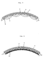
- a fifth lining material adapted for use in the above-mentioned lining method, characterized in that it comprises a first tubular textile jacket in the above-mentioned fourth lining material having an air impervious layer comprised of rubber or a synthetic resin bonded onto the outer surface thereof, and a second tubular textile jacket formed by weaving wefts and warps in a tubular shape, said wefts in the second textile jacket consisting of low elongation high tensile strength filament yarns and being laid in such a manner that they extend substantially without any slack, said second tubular textile jacket being fitted loosely in said first tubular textile jacket.
- This fifth lining material (refer to Figs. 6 and 7) is constructed such that the above-mentioned second tubular textile jacket 2 is fitted in the first or outer tubular textile jacket 2', and the outer tubular textile jacket 2' has an air impervious layer 3 comprised of rubber or a synthetic resin bonded onto the outer surface thereof.
- the above-mentioned outer tubular textile jacket 2' is formed by weaving warps 4' and wefts 5'' in a tubular shape and has the above-mentioned air impervious layer 3 bonded onto the outer surface thereof.
- the above-mentioned inner tubular textile jacket 2 is also formed by weaving warps 4 and wefts 5 in a tubular shape, and as for the wefts 5, low elongation high tensile strength filament yarns such as glass fiber yarns are used and laid substantially without any slack.
- the wefts 5 glass fiber yarns treated by bulking process should preferably be used.
- the warps 4 any suitable synthetic fiber yarns such as polyester yarns can be used.
- This inner tubular textile jacket 2 is fitted loosely in the outer tubular textile jacket 2', and a part thereof forms a folded portion 14.
- a sixth lining material is provided.
- the sixth lining material (refer to Figs. 8 and 9) is constructed such that the above-mentioned first tubular textile jacket 2' has an air impervious layer 3 comprised of rubber or a synthetic resin bonded onto the outer surface thereof, and a tubular unwoven fabric 15 is fitted in the first tubular textile jacket 2', and further the above-mentioned second tubular textile jacket 2 is fitted in the tubular unwoven fabric 15.
- the above-mentioned first tubular textile jacket 2' that is; the outer tubular textile jacket is formed by weaving warps 4' and wefts 5'' in a tubular shape and has the aforementioned air impervious layer 3 formed or bonded onto the outer surface thereof.
- tubular unwoven fabric 15 an unwoven fabric made up of synthetic fiber yarns such as polyester yarns, etc. can be used, and also an unwoven fabric made up of low elongation high tensile strength fiber yarns such as glass fiber yarns, etc. may be used. Further, as for this unwoven fabric 15, either a tubular molded unwoven fabric or a tubular unwoven fabric which is formed by rounding a sheet of unwoven fabric and joining both edges thereof can be used.
- the above-mentioned inner tubular textile jacket 2 is also formed by weaving warps 4 and wefts 5 in a tubular shape, and as for the wefts 5, low elongation high tensile strength yarns such as glass fiber yarns, etc. are used and laid substantially without any slack.
- the wefts 5 glass fiber yarns which have been subjected to bulking treatment should preferably be used.
- suitable synthetic fiber yarns such as polyester yarns, etc. can be used.
- This inner tubular textile jacket 2 is fitted loosely in the tubular unwoven fabric 15, and a part thereof forms a folded portion 14.
- low elongation high tensile strength filament yarns such as those made up of glass fiber yarns and aromatic polyamide filament yarns, etc. can also be used.
- yarns formed by intertwisting polyester yarns with polyester spun yarns or polyester twisted long filament yarns should preferably be used in order to improve the adhesive bonding power between the outer tubular textile jacket 2' and the air impervious layer 3.
- the thicknesses and weave densities of these warps 4' and the wefts 5'' vary with the bore of a pipeline to be lined and the purpose of use, however, it is generally preferable to form the outer tubular textile jacket 2' by densely weaving yarns having a thickness in the range of about 55.6 to 555.6 tex (500 to 5,000 d).
- the inner tubular textile jacket 2 laid in the fifth and sixth lining materials according to the present invention will now be described below.
- wefts 5 laid in this tubular textile jacket 2 low elongation high tensile strength filament yarns are used.
- yarns which are sufficiently thicker than the wefts 5'' laid in the outer tubular textile jacket 2' should preferably be used.
- the inner tubular textile jacket 2 is impregnated with a reaction-curing type resin.
- a reaction-curing type resin epoxy resin and unsaturated polyester resin are used most commonly. Therefore, as for the wefts 5 used in the inner tubular textile jacket 2, glass fiber yarns which are excellent in affinity with epoxy resin or unsaturated polyester resin and which are capable of forming a composite material having a high modulus of elasticity by using such a resin as a matrix thereof should preferably be used.
- the thickness of the wefts 5 vary with the required degree of shape retaining property of the lining layer against external pressures, but should preferably be sufficiently thicker than that of the weft 5'' laid in the outer tubular textile jacket 2' in order to ensure that the inner tubular textile jacket 2 having a thickness of about 2 to 10 mm is formed.
- air jet method and steam jet method are known.
- warps 4 laid in the inner tubular textile jacket ordinary synthetic fiber yarns such as polyester yarns and nylon yarns, etc. can be used, and also yarns identical to the warps 4' laid in the outer tubular textile jacket 2' may be used.
- the wefts 5 should preferably be laid substantially without any slack and at a considerable density. At least in no load condition, more than 50% of the inner surface of the lining material should desirably be covered with the wefts 5. If the rate of covering the lining material with the wefts 5 is low, then the portions of the lining material which are not covered with the wefts 5 cannot be impregnated with the reaction-curing type resin thus lowering the content of the resin in the lining material and rendering it impossible to enhance the shape retaining property of the lining material sufficiently.
- the warps 4 should preferably be laid at intervals of spacing much wider than that of the warps 4' laid in the outer tubular textile jacket 2'.
- the fifth lining material in order to give the lining material a satisfactory shape retaining property against external pressures, it is possible to increase or decrease the thickness of the lining material by adjusting the thickness of the wefts 5 laid in the inner tubular textile jacket 2.
- the sixth lining material is used and a tubular unwoven fabric 15 is laid between the outer tubular textile jacket 2' and the inner tubular textile jacket 2 so that the thickness of the lining material can be increased and a satisfactory shape retaining property against external pressures can be secured.
- the seventh lining material is a liner adapted for use in the above-mentioned lining method, characterized in that it comprises a tubular textile jacket having an air impervious layer comprised of rubber or a synthetic resin bonded onto the outer surface thereof, said tubular textile jacket being formed of a multi-plies woven fabric and the wefts laid in the inner ply of the woven fabric; that is; the wefts on the side of the inner surface of the tubular textile jacket adapted to be bonded onto the inner surface of a pipeline in the lined condition consist of low elongation high tensile strength filament yarns.
- the seventh lining material (refer to Fig. 10) comprises a tubular textile jacket 6 formed by weaving warps and wefts, said tubular textile jacket 6 having an air impervious layer 3 comprised of rubber or a synthetic resin bonded onto the outer surface thereof; that is; on the side of the inner surface of the tubular textile jacket adapted to be bonded to the inner surface of a pipeline to be lined, characterized in that said tubular textile jacket 6 is formed of a multi-plies woven fabric, and wefts 16 laid in the inner ply of the multi-plies woven fabric; that is; the wefts on the side of the inner surface of the tubular textile jacket adapted to be bonded onto the inner surface of a pipeline in the lined condition consist of low elongation high tensile strength filament yarns.
- This tubular textile jacket 6 is formed by a multi-plies woven fabric (an example of a two-plies woven fabric is shown in Fig. 10).
- the multi-plies woven fabric, the outer woven fabric 17 thereof has the aforementioned air impervious layer 3 bonded onto the outer surface thereof.
- the outer woven fabric 17 is formed by weaving warps 4 and wefts 5' in a tubular shape.
- low elongation high tensile strength filament yarns are used as wefts 16 thereof.
- the inner woven fabric 18 is woven more coarsely than the outer woven fabric 17.
- the inner woven fabric 18 is fastened to the outer woven fabric 17 by means of fastening yarns 8.
- Fig. 10 an example of a two-plies woven fabric is shown in Fig. 10
- the multi-plies woven fabric, the outer woven fabric 17 thereof has the aforementioned air impervious layer 3 bonded onto the outer surface thereof.
- the outer woven fabric 17 is formed by weaving
- the yarns for fastening the inner woven fabric 18 are denoted with reference numeral 4(8). This implies that the warps 4 forming the outer woven fabric 17 are used as the fastening yarns 8. Unlike this example, fastening yarns separate from the warps 4 may be used independently to fasten the inner woven fabric 18 to the outer woven fabric 17.
- polyester yarns having a high tensile strength and an ultimate elongation of about ten and several percent should preferably be used.
- low elongation high tensile strength filament yarns such as glass fiber yarns and aromatic polyamide fiber yarns, etc. may also be used.
- yarns formed by intertwisting polyester filament yarns with polyester spun yarns or polyester twisted long filament yarns should preferably be used.
- the thicknesses and weave densities of these warps 4 and wefts 5' vary with the bore of a pipeline to be lined and the purpose of use, however, it is generally preferable to form the outer woven fabric 17 by densely weaving yarns having a thickness in the range of 55.6 to 555.6 tex (500 to 5,000 d).
- the inner woven fabric 18 will be described.
- the wefts 16 to be laid in the inner woven fabric 18 high tensile strength yarns are used generally.
- yarns which are sufficiently thicker than the wefts 5' forming the outer woven fabric 17 should preferably be used.
- the tubular textile jacket 6 is impregnated with a reaction-curing type resin.
- a reaction-curing type resin epoxy resin and unsaturated polyester resin are used most commonly.
- glass fiber yarns which are excellent in affinity with epoxy resin and unsaturated polyester resin and which are capable of forming a composite material having a high modulus of elasticity by using such a resin as the matrix thereof should preferably be used.
- the thickness of the wefts 16 varies with the required degree of shape retaining property of the lining layer against external pressures.
- the thickness of the wefts 16 should adequately be such a magnitude as to ensure that the thickness of the inner woven fabric 18 becomes about 2 to 10 mm.
- the bulking treatment process are air jet method and steam jet method.
- warps 19 to be laid in the inner fabric ordinary synthetic fiber yarns such as polyester yarns and nylon yarns, etc. can be used, and also yarns identical to the warps 4 for use in the outer woven fabric 17 may be used.
- the wefts 16 should preferably be laid at a considerable density on the inner surface of the outer woven fabric 17. At least in no load condition, more than 50% of the inner surface of the outer woven fabric 17 should desirably be covered with the wefts 16. If the covering rate with the wefts 16 is low, then the portions of the outer woven fabric 17 between the adjoining wefts 16 cannot be impregnated with the reaction-curing type resin thus lowering the content of the resin in the lining material and making it impossible to enhance sufficiently the shape retaining property of the lining layer against external pressures.
- the warps 19 should preferably be laid at much wider intervals than those of the warps 4 laid in the outer woven fabric 17.
- the portions of the wefts 16 between the adjoining warps 19 become long and can be impregnated with large quantities of the reaction-curing type resin.
- the method of forming the inner woven fabric 18 and the outer woven fabric 17 is not limited to a particular one, and a suitable weaving method such as plain weave and twill weave, etc. can be used.
- the material of the air impervious layer 3 in this lining material is selected depending on the kind of a pipeline to be lined and the kind of the fluid to flow therethrough, and any one having an excellent durability is used.
- the tubular textile jacket 6 is shown as being comprised of a double structure formed by the outer woven fabric 17 and the inner woven fabric 18. It is possible, however, to locate intermediate woven fabrics between these two woven fabrics 17 and 18 so as to form a multi-plies woven fabric structure having three or more layers.
- the innermost woven fabric in the multi-plies woven fabric structure that is; the one forming the surface adapted to be adhesively bonded to the inner surface of a pipeline in the lined condition, low elongation high tensile strength filament yarns are used as the wefts thereof.
- This seventh lining material can meet the requirements for the above-mentioned lining material for pipelines such as enhanced earthquake resistance and shape retaining property against external pressures and also the requirement that the expansion in diameter thereof should be limited. Furthermore, the use of the above-mentioned structure enables the formation of a lining layer having a satisfactory shape retaining property against external pressures without having to increase the thickness of the woven fabric 17 bonded to the air impervious layer and those of the intermediate woven fabrics beyond the required values. Further, since the above-mentioned low elongation high tensile strength filament yarns can be made sufficiently thick, a lining layer having a high degree of shape retaining property against external pressures can be obtained.
- the portions of the wefts 16 each consisting of high tensile strength yarn between the adjoining fastening yarns on the surface of the outer woven fabric 17 become long so that even when large quantities of high tensile strength yarns are used the resultant lining material is very flexible and can be handled easily, and also in case the lining material is inserted into a pipeline while turning it inside out, the lining material can be evaginated easily and the evagination thereof can be effected simply under a low fluid pressure.
- the quantity of the reaction-curing type resin with which the inner woven fabric is to be impregnated can be increased thereby securing a required thickness of the lining material.
- the adhesive bonding power between the tubular textile jacket 6 and the air impervious layer 3 can be enhanced.
- a superior lining material can be provided in case highly flexible yarns are used as the warps forming the textile jacket. That is to say; as for such highly flexible yarns for use as the warps, elastic yarns such as polyurethane elastic yarns, etc. coiled with synthetic fiber yarns can be used, or alternatively synthetic fibers treated by crimping process may be used. Further, as for the fibers which are highly flexible per se, polybutylene terephthalate fibers can also be used, and polybutylene terephthalate fiber yarns treated by crimping process are most suitable for this purpose.
- the above-mentioned elastic yarns besides polyurethane elastic yarns, rubber yarns, etc. may be used. However, since rubber yarns are liable to deteriorate by ultra-violet rays or by heat, polyurethane elastic yarns are more suitable. Further, the synthetic fiber yarns to be coiled around the elastic yarns serve to enhance the shrinkage of the warps, and so, besides filament yarns and spun yarns of synthetic fibers, crimped synthetic fiber yarns can be used.
- polybutylene terephthalate fiber yarns As for the warps, it is preferable to use polybutylene terephthalate fiber yarns.
- Polybutylene terephthalate fiber yarns per se possess an ultimate elongation of about 30% and are especially highly flexible among synthetic fiber yarns and so are suitable as the above-mentioned warps.
- polybutylene terephthalate fiber yarns treated by crimping process the flexibility of the lining material can be enhanced thereby providing a more preferable lining material.
- a lining material to be applied to a pipeline having a nominal diameter of 150 mm was produced as follows.
- Tubular Textile Jacket Weight of fibrous layer g/m
- Thickness of fibrous layer mm
- 1.0 Longitudinal strength kg/cm
- 290 Transverse strength kg/cm
- 163 Breaking pressure kg/cm 2
- 1.37 Width of tubular textile jacket in flattened state mm
- a lining material to be applied to a pipeline having a nominal diameter of 150 mm was produced as follows.
- bulky yarns each being made up of eight twisted nylon yarns having a thickness of 188.9 tex (1,700 d) treated by bulking process were used and laid spirally at a rate of 13 lengths over a span of 10 centimeters inside of the tubular textile jacket, and the bulky yarns were fastened by the warps six lengths apart so as to form a fibrous layer.
- thermoplastic polyester elastic resin was formed on the outer surface of the fibrous layer thus obtained.
- a lining material to be applied to a pipeline having a nominal diameter of 150 mm was produced as follows.
- the warps for use in a tubular textile jacket to be produced 240 lengths of double-yarns each being formed by four twisted polyester filament yarns having a thickness of 122.2 tex (1,100 d) were used, whilst as for the wefts thereof, 39 lengths of yarns each being formed by intertwisting one length of polyester filament yarn having a thickness of 122.2 tex (1,100 d) with 6 lengths of polyester spun yarns with 20 yarn count number were picked up over a span of 10 centimeters so as to form a tubular textile jacket using plain weave method.
- bulky yarns each being formed by four twisted glass fiber yarns having a thickness of about 888.8 tex (8,000 d) treated by bulking process were laid spirally at a rate of 13 lengths over a span of 10 centimeters inside of the tubular textile jacket, and the bulky yarns were fastened by the warps six lengths apart so as to form a fibrous layer.
- thermoplastic polyester elastic resin was formed on the outer surface of the fibrous layer thus obtained.
- a lining material to be applied to a pipeline having a nominal diameter of 150 mm was produced as follows.
- a lining material to be applied to a pipeline having a nominal diameter of 150 mm was produced as follows.
- the warps for use in a tubular textile jacket to be produced 240 lengths of double-yarns each being formed by four twisted polyester filament yarns having a thickness of 122.2 tex (1,100 d) were used, whilst as for the wefts thereof, 39 lengths of yarns each being formed by intertwisting one length of polyester filament yarn having a thickness of 122.2 tex (1,100 d) with 6 lengths of polyester spun yarns with 20 yarn count number were picked up over a span of 10 centimeters so as to form a tubular textile jacket using plain weave method.
- thermoplastic polyester elastic resin was formed on the outer surface of the fibrous layer thus produced.
Claims (19)
- Matériau de garniture tubulaire comprenanta) une chemise tubulaire en textile (2, 2', 17) comprenant des chaínes (4, 4') qui s'étendent dans la direction longitudinale de la chemise et des trames (5, 5'),b) une couche adhésive sur la surface intérieure du matériau tubulaire,c) une couche imperméable à l'air (3) de caoutchouc ou de résine synthétique liée à la surface extérieure de la chemise (2, 2', 17)
caractérisé en ce qued) les trames (5, 5') sont constituées de fils à filaments ou de fibres, dans lesquelles au moins une partie des filaments ou des fibres sont des Super Fibres présentant un faible allongement à la rupture et une résistance à la traction d'au moins 2,45 GPa (250 kg/mm2), ete) les chaínes (4, 4') sont constituées de fils synthétiques ordinaires autres que des fils en Super Fibre. - Matériau de garniture selon la revendication 1, caractérisé en ce que les chaínes s'étendent en ligne droite et les trames (5, 5') s'étendent suivant une configuration courbée.
- Matériau de garniture selon la revendication 2, dans lequel les trames courbées (5, 5') assurent un pourcentage en frisures de 7 à 25 %.
- Matériau de garniture selon l'une quelconque des revendications 1 à 3, caractérisé par des fils (7, 12, 16) qui sont plus épais que les trames (5, 5') et qui sont disposés sur la surface intérieure de la chemise tubulaire en textile (2, 2', 17), lesdits fils épais (7, 12, 16) étant fixés à la chemise tubulaire en textile par intervalles et formant une couche fibreuse en même temps que la chemise tubulaire en textile.
- Matériau de garniture selon la revendication 4, caractérisé en ce que les intervalles des fils épais sont de plusieurs centimètres par rapport au diamètre de la chemise de 150 mm.
- Matériau de garniture selon l'une quelconque des revendications 1 à 3, dans lequel un élément fibreux tubulaire (10) est monté à la surface intérieure de la chemise tubulaire en textile (2).
- Matériau de garniture selon la revendication 6, caractérisé en ce que ledit élément fibreux tubulaire (10) est constitué d'une étoffe non tissée ou d'une étoffe en textile.
- Matériau de garniture selon l'une quelconque des revendications 1 à 7, dans lequel une autre chemise en textile est placée entre la première chemise tubulaire en textile (2) et la couche imperméable à l'air (3).
- Matériau de garniture selon la revendication 8, caractérisé en ce que les fils des trames formant ladite chemise tubulaire intérieure en textile (2) sont plus épais que les trames constituant la chemise extérieure tubulaire en textile.
- Matériau de garniture selon la revendication 8 ou 9, dans lequel une partie de la première chemise tubulaire en textile (2) forme une portion pliée (14).
- Matériau de garniture selon la revendication 8, 9 ou 10, caractérisé en ce qu'une étoffe tubulaire non tissée (15) est adaptée entre la première chemise tubulaire en textile (2) et la seconde chemise tubulaire en textile (2').
- Matériau de garniture tubulaire comprenant :a) une chemise tubulaire en textile (2') comportant des chaínes qui s'étendent dans la direction longitudinale de la chemise, et des trames,b) une couche adhésive sur la surface intérieure du matériau tubulaire,c) une couche imperméable à l'air de caoutchouc ou de résine synthétique liée à la surface extérieure de la chemise, caractérisé en ce que :
des fils à filaments en Super Fibres ayant un faible allongement à la rupture et une résistance à la traction d'au moins 2,45 GPa (250 kg/mm2) sont places sur la surface intérieure de la chemise tubulaire en textile suivant sa direction circonférentielle, et sont fixés à la chemise par intervalles. - Matériau de garniture selon la revendication 12, caractérisé en ce que les fils à filaments de faible allongement et de résistance à la traction élevée sont plus épais que les trames constitutant la chemise en textile tubulaire (2').
- Matériau de garniture selon l'une quelconque des revendications 1 à 13, caractérisé en ce que les chaínes disposées dans chacune desdites chemises tubulaires en textile sont constituées de fils élastiques.
- Matériau de garniture selon l'une quelconque des revendications 1 à 14, caractérisé en ce que lesdits fils à filaments de faible allongement et de résistance à la traction élevée sont des fils à filaments de fibres de verre dont le diamètre des filaments est de 6 µm ou moins.
- Matériau de garniture selon l'une quelconque des revendications 1 à 15, caractérisé en ce que lesdits fils à filaments de faible allongement et de résistance à la traction élevée sont des fils épais.
- Matériau de garniture selon l'une quelconque des revendications 1 à 16, caractérisé en ce que les chaínes disposées dans chacune desdites chemises tubulaires en textile sont constituées de fils à filaments de polyester et de longs fils à filaments torsadés de polyester ou de fils filés de polyester.
- Utilisation des matériaux de garniture selon les revendications 1 à 17, pour la garniture de pipelines.
- Procédé pour garnir des pipelines ou des tuyaux comprenant l'évagination d'un matériau de garniture selon l'une quelconque des revendications 1 à 17 en un tuyau ou un pipeline sous l'action de la pression d'un fluide.
Applications Claiming Priority (7)
| Application Number | Priority Date | Filing Date | Title |
|---|---|---|---|
| JP25137587A JPH0692120B2 (ja) | 1987-10-05 | 1987-10-05 | 管路の内張り材 |
| JP251375/87 | 1987-10-05 | ||
| JP25137587 | 1987-10-05 | ||
| JP286643/87 | 1987-11-12 | ||
| JP62286643A JPH0692121B2 (ja) | 1987-10-05 | 1987-11-12 | 管路の内張り材及びその製造方法 |
| JP28664387 | 1987-11-12 | ||
| PCT/JP1988/001015 WO1989002821A1 (fr) | 1987-10-05 | 1988-10-05 | Materiau de garnissage de conduites |
Publications (4)
| Publication Number | Publication Date |
|---|---|
| EP0370108A4 EP0370108A4 (fr) | 1990-02-20 |
| EP0370108A1 EP0370108A1 (fr) | 1990-05-30 |
| EP0370108B1 EP0370108B1 (fr) | 1996-09-11 |
| EP0370108B2 true EP0370108B2 (fr) | 2000-04-26 |
Family
ID=26540165
Family Applications (1)
| Application Number | Title | Priority Date | Filing Date |
|---|---|---|---|
| EP88908744A Expired - Lifetime EP0370108B2 (fr) | 1987-10-05 | 1988-10-05 | Materiau de garnissage de conduites |
Country Status (7)
| Country | Link |
|---|---|
| US (1) | US5077107A (fr) |
| EP (1) | EP0370108B2 (fr) |
| JP (1) | JPH0692121B2 (fr) |
| AU (2) | AU2530788A (fr) |
| DE (1) | DE3855537T3 (fr) |
| DK (1) | DK166573B1 (fr) |
| WO (1) | WO1989002821A1 (fr) |
Families Citing this family (74)
| Publication number | Priority date | Publication date | Assignee | Title |
|---|---|---|---|---|
| US5535786A (en) * | 1990-04-06 | 1996-07-16 | Suomen Putkisaneeraus Oy | Method for repairing flow conduits, and repair material |
| BE1004649A3 (fr) * | 1991-03-04 | 1993-01-05 | Capelle Robert | Gaine tubulaire adaptee au garnissage interieur des conduites tubulaires. |
| DE4113378C1 (fr) * | 1991-04-24 | 1992-11-12 | Siegfried 1000 Berlin De Schwert | |
| US5451351A (en) | 1991-09-13 | 1995-09-19 | Composite Components, Inc. | Method for rehabilitating a pipe with a liner having an electrically conductive layer |
| JP2537111B2 (ja) * | 1991-12-06 | 1996-09-25 | 有限会社横島 | 管ライニング材への樹脂含浸方法 |
| CA2121711A1 (fr) * | 1993-05-03 | 1994-11-04 | Giulio Catallo | Tuyau flexible a gaine renforcee |
| AU694172B2 (en) * | 1994-04-11 | 1998-07-16 | Cant, Richard Samuel | Lining material |
| AUPM499194A0 (en) * | 1994-04-11 | 1994-05-05 | Cant, Richard Samuel | Lining of piping |
| US5501248A (en) * | 1994-06-23 | 1996-03-26 | Lmk Enterprises, Inc. | Expandable pipe liner and method of installing same |
| US5653555A (en) | 1995-05-19 | 1997-08-05 | Inliner, U.S.A. | Multiple resin system for rehabilitating pipe |
| US5699838A (en) | 1995-05-22 | 1997-12-23 | Inliner, U.S.A. | Apparatus for vacuum impregnation of a flexible, hollow tube |
| US7498509B2 (en) | 1995-09-28 | 2009-03-03 | Fiberspar Corporation | Composite coiled tubing end connector |
| US8678042B2 (en) | 1995-09-28 | 2014-03-25 | Fiberspar Corporation | Composite spoolable tube |
| US5921285A (en) * | 1995-09-28 | 1999-07-13 | Fiberspar Spoolable Products, Inc. | Composite spoolable tube |
| GB9626060D0 (en) * | 1996-12-16 | 1997-02-05 | United Utilities Plc | Thermoplastic composite products |
| FR2762892B1 (fr) * | 1997-04-30 | 1999-07-02 | Westaflex Automobile | Tuyau pour le transport de fluides gazeux, notamment dans les automobiles |
| US5971030A (en) * | 1997-06-06 | 1999-10-26 | Maimets; Lembit | Apparatus and method for repairing pressure pipes and for securing other elements with a curable sealant |
| US5931198A (en) * | 1997-10-30 | 1999-08-03 | Raji; Brian Behzad | Fabric reinforced pipe |
| DE19810373C2 (de) * | 1998-03-10 | 2001-08-23 | Raedlinger Maschinen Und Anlag | Verfahren zum Verlegen von Hochdruckfluidleitungen |
| US6737134B2 (en) * | 1998-05-06 | 2004-05-18 | Ameron International Corporation | Abrasion resistant pipe |
| US6129119A (en) * | 1998-09-11 | 2000-10-10 | Karl Weiss Hoch - Tief - Und Rohrleitungsbau Gmbh & Co. | Flexible tube for lining pipes and ducts as well as method and an apparatus for manufacturing thereof |
| US6703091B1 (en) | 1999-04-16 | 2004-03-09 | Roger H. Walker | Structural lining system for pipes and method for applying same |
| US6540438B2 (en) * | 2000-06-27 | 2003-04-01 | Terre Hill Silo Company | Inflatable underground structure liner |
| KR100379747B1 (ko) * | 2000-07-22 | 2003-04-11 | 한국과학기술원 | 보호막을 갖춘 수지이송성형법을 이용한 하수관보수·보강 공법 |
| GB2391600B (en) | 2001-04-27 | 2005-09-21 | Fiberspar Corp | Buoyancy control systems for tubes |
| US6607010B1 (en) * | 2001-05-10 | 2003-08-19 | Southeastern Universities Res. Assn, Inc. | Flexible collapse-resistant and length-stable vaccum hose |
| US6708729B1 (en) * | 2002-03-14 | 2004-03-23 | Instituform B.V. | Fiber reinforced composite liner for lining an existing conduit and method of manufacture |
| US6932116B2 (en) * | 2002-03-14 | 2005-08-23 | Insituform (Netherlands) B.V. | Fiber reinforced composite liner for lining an existing conduit and method of manufacture |
| US6732763B2 (en) * | 2002-05-24 | 2004-05-11 | Lantor, Inc. | Stretch-resistant pipe liner |
| US6926037B2 (en) * | 2002-12-17 | 2005-08-09 | Wellstream International Limited | Collapse tolerant flexible pipe and method of manufacturing same |
| EP1443257A1 (fr) | 2003-02-03 | 2004-08-04 | NordiTube Technologies AB | Matériau pour le revêtement interne de canalisations |
| CA2545025C (fr) * | 2003-11-07 | 2011-12-20 | Insituform (Netherlands) B.V. | Gaine durcie sur place et renforcee longitudinalement |
| CA2460297C (fr) | 2004-02-26 | 2016-01-12 | Industrial Rubber Products, Inc. | Garniture en caoutchouc-polyurethanne |
| CA2490176C (fr) | 2004-02-27 | 2013-02-05 | Fiberspar Corporation | Tuyau renforce de fibres transferable sur touret |
| FR2869971B1 (fr) * | 2004-05-05 | 2006-07-28 | Freyssinet Internat Stup Soc P | Procede de renforcement d'un tuyau cylindrique enterre |
| US20060151042A1 (en) * | 2005-01-12 | 2006-07-13 | Stringfellow William D | Pipe liner |
| US7374127B2 (en) * | 2005-01-12 | 2008-05-20 | Smart Pipe Company, Inc. | Systems and methods for making pipe liners |
| US8567448B2 (en) | 2007-12-26 | 2013-10-29 | Smart Pipe Company, Inc. | Methods and systems for in situ pipe lining |
| US8567450B2 (en) | 2005-01-12 | 2013-10-29 | Smart Pipe Company Lp | Methods and systems for in situ manufacture and installation of non-metallic high pressure pipe and pipe liners |
| EP1715239A1 (fr) * | 2005-04-22 | 2006-10-25 | NordiTube Technologies AB | Matériau de revêtement tubulaire polymérisable aux UV pour conduites |
| US20070113971A1 (en) * | 2005-11-18 | 2007-05-24 | Insituform (Netherlands) B.V. | Longitudinally reinforced cured in place liner and reinforced coating |
| US8187687B2 (en) | 2006-03-21 | 2012-05-29 | Fiberspar Corporation | Reinforcing matrix for spoolable pipe |
| US7320341B2 (en) * | 2006-05-17 | 2008-01-22 | 3M Innovative Properties Company | Protective liner for slurry pipelines |
| CA2619808C (fr) | 2007-02-02 | 2015-04-14 | Fiberspar Corporation | Tube multicellulaire enroulable |
| US8746289B2 (en) | 2007-02-15 | 2014-06-10 | Fiberspar Corporation | Weighted spoolable pipe |
| CA2641492C (fr) | 2007-10-23 | 2016-07-05 | Fiberspar Corporation | Conduite chauffee et methodes de transport de fluide visqueux |
| US9453606B2 (en) * | 2007-12-26 | 2016-09-27 | Smart Pipe Company, Inc. | Movable factory for simultaneous mobile field manufacturing and installation of non-metallic pipe |
| US9127546B2 (en) | 2009-01-23 | 2015-09-08 | Fiberspar Coproation | Downhole fluid separation |
| US8590575B2 (en) * | 2009-03-27 | 2013-11-26 | Perma-Liner Industries, Llc | Scrim-enforced pipe liner |
| US9310014B2 (en) | 2009-12-07 | 2016-04-12 | Smart Pipe Company L.P. | Systems and methods for making pipe, and method of installing the pipe in a pipeline |
| US8955599B2 (en) | 2009-12-15 | 2015-02-17 | Fiberspar Corporation | System and methods for removing fluids from a subterranean well |
| CA2783764C (fr) | 2009-12-15 | 2017-08-15 | Fiberspar Corporation | Systeme et procedes pour retirer des fluides d'un puits souterrain |
| US8678036B2 (en) * | 2010-04-30 | 2014-03-25 | Johann Kübel | Sealing hose |
| AT509805B1 (de) * | 2010-04-30 | 2014-05-15 | Kübel Johann Ing | Dichtschlauch |
| US9074718B2 (en) * | 2011-01-10 | 2015-07-07 | LMK Technoloogies, LLC | Liner tube with non-stretching material |
| JP2014517220A (ja) | 2011-04-18 | 2014-07-17 | ファイフ カンパニー,エルエルシー | 保護用拡張ライナおよび既存パイプの強化 |
| CN102644829B (zh) * | 2012-04-05 | 2013-10-30 | 青岛科技大学 | 一种水下管线泄漏封堵用橡胶复合材料及其使用方法 |
| WO2014026190A1 (fr) | 2012-08-10 | 2014-02-13 | National Oilwell Varco, L.P. | Raccords de tubulure enroulés composites |
| EP2722157A1 (fr) * | 2012-10-18 | 2014-04-23 | Siegfried Schwert | Gaine, tuyau de pression réhabilité et procédé de réhabilitation d'un tuyau de pression |
| WO2014110544A1 (fr) * | 2013-01-14 | 2014-07-17 | Fyfe Co. Llc | Chemise très résistante et procédé d'utilisation |
| US10550987B2 (en) * | 2013-05-28 | 2020-02-04 | Sanexen Environmental Services Inc. | Seismic reinforced underground water conduit |
| US20140356074A1 (en) * | 2013-05-28 | 2014-12-04 | Sanexen Environmental Services, Inc. | Seismic reinforced underground water conduit |
| CN106662284A (zh) | 2014-06-16 | 2017-05-10 | 法伊夫有限责任公司 | 管道的修理 |
| WO2016009361A1 (fr) | 2014-07-14 | 2016-01-21 | Fyfe Co. Llc | Procédé de renforcement d'une conduite à l'aide d'un revêtement de conduite, conduite renforcée et procédé d'imperméabilisation d'une conduite renforcée |
| US9757599B2 (en) | 2014-09-10 | 2017-09-12 | Dymat Construction Products, Inc. | Systems and methods for fireproofing cables and other structural members |
| US9993992B2 (en) | 2015-04-17 | 2018-06-12 | Fyfe Co. Llc | Structural fabric useful for lining pipe |
| CA2904683C (fr) * | 2015-06-17 | 2022-05-03 | Sanexen Environmental Services Inc. | Conduit d'eau souterrain renforce pour resister aux secousses sismiques |
| US10077855B2 (en) | 2015-09-22 | 2018-09-18 | Ina Acquisition Corp. | Method of lining pipe with high strength liner, high strength liner, and pipe lined with high strength liner |
| US11173634B2 (en) | 2018-02-01 | 2021-11-16 | Ina Acquisition Corp | Electromagnetic radiation curable pipe liner and method of making and installing the same |
| US10704728B2 (en) | 2018-03-20 | 2020-07-07 | Ina Acquisition Corp. | Pipe liner and method of making same |
| EA202191692A1 (ru) * | 2018-12-18 | 2021-12-31 | Эни С.П.А. | Композитный трубчатый элемент и способ его изготовления |
| US11401631B2 (en) * | 2019-10-28 | 2022-08-02 | Federal-Mogul Powertrain Llc | Impact resistant, wrappable multilayered woven sleeve and method of construction thereof |
| US11371324B2 (en) | 2020-07-16 | 2022-06-28 | Saudi Arabian Oil Company | Method and apparatus for installing infield flexible liner of downhole tubing |
| CN112875557A (zh) * | 2021-02-25 | 2021-06-01 | 中国电建集团西北勘测设计研究院有限公司 | 一种用于勘测地下管涵的钢丝绳架设方法 |
Family Cites Families (5)
| Publication number | Priority date | Publication date | Assignee | Title |
|---|---|---|---|---|
| GB1340068A (en) * | 1970-09-22 | 1973-12-05 | Insituform Pipes & Structures | Lining of surfaces defining passageways |
| JPS601178B2 (ja) * | 1979-07-03 | 1985-01-12 | 東京瓦斯株式会社 | 管路の内張り基材 |
| JPS59225920A (ja) * | 1983-06-07 | 1984-12-19 | Tokyo Gas Co Ltd | 管路の内張り材 |
| JPS59225921A (ja) * | 1983-06-07 | 1984-12-19 | Tokyo Gas Co Ltd | 管路の内張り材 |
| JPS60132323U (ja) * | 1984-02-14 | 1985-09-04 | 東京瓦斯株式会社 | 管路の内張り材 |
-
1987
- 1987-11-12 JP JP62286643A patent/JPH0692121B2/ja not_active Expired - Lifetime
-
1988
- 1988-10-05 EP EP88908744A patent/EP0370108B2/fr not_active Expired - Lifetime
- 1988-10-05 DE DE3855537T patent/DE3855537T3/de not_active Expired - Lifetime
- 1988-10-05 AU AU25307/88A patent/AU2530788A/en active Granted
- 1988-10-05 AU AU25307/88A patent/AU612200B2/en not_active Ceased
- 1988-10-05 US US07/364,421 patent/US5077107A/en not_active Expired - Lifetime
- 1988-10-05 WO PCT/JP1988/001015 patent/WO1989002821A1/fr active IP Right Grant
-
1989
- 1989-06-02 DK DK271489A patent/DK166573B1/da active IP Right Grant
Also Published As
| Publication number | Publication date |
|---|---|
| DK166573B1 (da) | 1993-06-14 |
| WO1989002821A1 (fr) | 1989-04-06 |
| AU612200B2 (en) | 1991-07-04 |
| JPH0692121B2 (ja) | 1994-11-16 |
| AU2530788A (en) | 1989-04-18 |
| US5077107A (en) | 1991-12-31 |
| EP0370108A4 (fr) | 1990-02-20 |
| DE3855537T3 (de) | 2000-12-21 |
| DE3855537D1 (de) | 1996-10-17 |
| JPH01127328A (ja) | 1989-05-19 |
| DK271489A (da) | 1989-06-02 |
| EP0370108A1 (fr) | 1990-05-30 |
| EP0370108B1 (fr) | 1996-09-11 |
| DE3855537T2 (de) | 1997-01-16 |
| DK271489D0 (da) | 1989-06-02 |
Similar Documents
| Publication | Publication Date | Title |
|---|---|---|
| EP0370108B2 (fr) | Materiau de garnissage de conduites | |
| US5164237A (en) | Lining material for pipelines | |
| US4681783A (en) | Tubular lining material for pipe lines | |
| US6932116B2 (en) | Fiber reinforced composite liner for lining an existing conduit and method of manufacture | |
| US6923217B2 (en) | Fiber reinforced composite liner for lining an existing conduit and method of manufacture | |
| EP0205621B1 (fr) | Materiau de revetement interne de conduits | |
| EP0288579B1 (fr) | Materiau de revetement interne de pipe-lines | |
| US20080277012A1 (en) | Reinforcing Liner | |
| US20060228501A1 (en) | Lining material for pipelines | |
| EP0392026A1 (fr) | Tube utilise pour le revetement interne d'une conduite | |
| GB2104996A (en) | Hose | |
| CA1339253C (fr) | Revetement servant a garnir la paroi interieure des tuyauteries | |
| JPS62117845A (ja) | 丸織布とこれを組合わせたホ−ス | |
| JPS6334017B2 (fr) | ||
| JP4496656B2 (ja) | 内張り材用基材、内張り材、及び管のライニング方法 | |
| JP2630919B2 (ja) | 管路の内張り材 | |
| JPH0829561B2 (ja) | 管路の内張り材 | |
| JPH0692120B2 (ja) | 管路の内張り材 | |
| JP2691286B2 (ja) | 管路の内張り材 | |
| PT90149B (pt) | Material de revestimento para condutas tubulares | |
| JPH0794146B2 (ja) | 管路の内張り材 | |
| JPH01165430A (ja) | 管路の内張り材 | |
| JPH01164885A (ja) | 管路 | |
| JPH0692122B2 (ja) | 管路の内張り材 | |
| WO1988000133A1 (fr) | Materiau de revetement pour conduite |
Legal Events
| Date | Code | Title | Description |
|---|---|---|---|
| PUAI | Public reference made under article 153(3) epc to a published international application that has entered the european phase |
Free format text: ORIGINAL CODE: 0009012 |
|
| 17P | Request for examination filed |
Effective date: 19890922 |
|
| AK | Designated contracting states |
Kind code of ref document: A1 Designated state(s): DE FR GB IT NL |
|
| 17Q | First examination report despatched |
Effective date: 19920504 |
|
| GRAH | Despatch of communication of intention to grant a patent |
Free format text: ORIGINAL CODE: EPIDOS IGRA |
|
| GRAA | (expected) grant |
Free format text: ORIGINAL CODE: 0009210 |
|
| GRAH | Despatch of communication of intention to grant a patent |
Free format text: ORIGINAL CODE: EPIDOS IGRA |
|
| AK | Designated contracting states |
Kind code of ref document: B1 Designated state(s): DE FR GB IT NL |
|
| REF | Corresponds to: |
Ref document number: 3855537 Country of ref document: DE Date of ref document: 19961017 |
|
| ITF | It: translation for a ep patent filed |
Owner name: MODIANO & ASSOCIATI S.R.L. |
|
| ET | Fr: translation filed |
Free format text: CORRECTIONS |
|
| PLBQ | Unpublished change to opponent data |
Free format text: ORIGINAL CODE: EPIDOS OPPO |
|
| PLBI | Opposition filed |
Free format text: ORIGINAL CODE: 0009260 |
|
| 26 | Opposition filed |
Opponent name: NORDITUBE TECHNOLOGIES AB Effective date: 19970610 |
|
| PLBF | Reply of patent proprietor to notice(s) of opposition |
Free format text: ORIGINAL CODE: EPIDOS OBSO |
|
| NLR1 | Nl: opposition has been filed with the epo |
Opponent name: NORDITUBE TECHNOLOGIES AB |
|
| PLBF | Reply of patent proprietor to notice(s) of opposition |
Free format text: ORIGINAL CODE: EPIDOS OBSO |
|
| PLBF | Reply of patent proprietor to notice(s) of opposition |
Free format text: ORIGINAL CODE: EPIDOS OBSO |
|
| PLAW | Interlocutory decision in opposition |
Free format text: ORIGINAL CODE: EPIDOS IDOP |
|
| PLAW | Interlocutory decision in opposition |
Free format text: ORIGINAL CODE: EPIDOS IDOP |
|
| PUAH | Patent maintained in amended form |
Free format text: ORIGINAL CODE: 0009272 |
|
| STAA | Information on the status of an ep patent application or granted ep patent |
Free format text: STATUS: PATENT MAINTAINED AS AMENDED |
|
| 27A | Patent maintained in amended form |
Effective date: 20000426 |
|
| AK | Designated contracting states |
Kind code of ref document: B2 Designated state(s): DE FR GB IT NL |
|
| ET3 | Fr: translation filed ** decision concerning opposition | ||
| NLR2 | Nl: decision of opposition | ||
| ITF | It: translation for a ep patent filed |
Owner name: MODIANO & ASSOCIATI S.R.L. |
|
| NLR3 | Nl: receipt of modified translations in the netherlands language after an opposition procedure | ||
| REG | Reference to a national code |
Ref country code: GB Ref legal event code: IF02 |
|
| PGFP | Annual fee paid to national office [announced via postgrant information from national office to epo] |
Ref country code: DE Payment date: 20071129 Year of fee payment: 20 Ref country code: NL Payment date: 20071029 Year of fee payment: 20 |
|
| PGFP | Annual fee paid to national office [announced via postgrant information from national office to epo] |
Ref country code: IT Payment date: 20071018 Year of fee payment: 20 |
|
| PGFP | Annual fee paid to national office [announced via postgrant information from national office to epo] |
Ref country code: GB Payment date: 20071018 Year of fee payment: 20 |
|
| REG | Reference to a national code |
Ref country code: GB Ref legal event code: PE20 Expiry date: 20081004 |
|
| PG25 | Lapsed in a contracting state [announced via postgrant information from national office to epo] |
Ref country code: NL Free format text: LAPSE BECAUSE OF EXPIRATION OF PROTECTION Effective date: 20081005 |
|
| NLV7 | Nl: ceased due to reaching the maximum lifetime of a patent |
Effective date: 20081005 |
|
| PGFP | Annual fee paid to national office [announced via postgrant information from national office to epo] |
Ref country code: FR Payment date: 20071031 Year of fee payment: 20 |
|
| PG25 | Lapsed in a contracting state [announced via postgrant information from national office to epo] |
Ref country code: GB Free format text: LAPSE BECAUSE OF EXPIRATION OF PROTECTION Effective date: 20081004 |